
Abstract
Because of the closed geographic conditions and the effect of uncertain factors during a catastrophe in an underground coal mine, a high failure rate of the sensor nodes after a disaster is a common phenomenon. To ensure normal communications after a disaster, an impact cushioning device is designed to ensure survival of the sensor nodes during the disasters like the tunnel collapse, gas explosion, and so on. First, a model for the spring absorbing system is built; an analysis based on the model shows that the impact cushioning device can survive the free impact due to the extremely short impact time and the small displacement despite the large force from the instantaneous impact. Second, a collision model between the impact cushioning device and the rock is built; an analysis based on the model shows that both the circuit boards and the shell of the device can survive a tunnel collapse because the maximum stress values of the shell material and the circuit boards during the collision process are much less than their yield strength values. Finally, we use a triangular wave to simulate the shock wave used to test the collision model. An analysis of the test shows that the shell of the device and circuit boards are still safe and reliable under the effects of a gas explosion for the same reason that the maximum stress values of the shell material and the circuit boards in the gas explosion process are much lower than their yield strength values.
Introduction
With complicated geological conditions, a terrible living environment, and a high frequency of major disaster accidents under a coal mine, the information support system plays a pivotal role in disaster information release and rescue navigation. 1 However, an underground power supply would be cut off by a gas or thermodynamic catastrophe, which can destroy communication lines and key routing equipment; as a result, a cable information system in a post-disaster situation might deviate from normal operations, thereby seriously hampering rescue efforts after the catastrophe.
Wireless sensor networks (WSNs) offer the following features: battery-powered, self-organize, redundant configuration, and low power requirements. Technically, WSNs can be applied to a coal mine safety risk-aversion and emergency rescue system because of the ability to collect and transmit information after severe coal mine disasters. 2 For example, Wang and Wang 3 proposed a method of replacing the gas detection cable communication system with a wireless communication system. Acero et al. 4 developed a SCADA system for the detection of explosive atmospheres in a coal mine using WSNs, which provided mathematical analysis and the measurement of the concentrations of the combustion gases in the atmosphere via a wireless data acquisition system. Liu et al. 5 proposed a positioning system of non-complete coverage of the whole tunnel network by measuring points based on WSNs. With the continuing development and widespread application of WSNs, the security and reliability of the sensor nodes become a central concern.
However, constrained by the closed geographic conditions and the effect of uncertain factors caused by the disaster, a high failure rate of the sensor node of WSNs is really common. Therefore, we must invent an impact cushioning device to resist the impact caused by a tunnel collapse, gas explosion, or mine flooding accident to ensure the nodes operate reliably after a catastrophe.
As the common equipment used in an underground coal mine, all the above explosion protection requirements should be satisfied. Research studies regarding the performance to resist the blast shock of different explosion-proof devices have been performed by many scholars. Wu 6 simulated the process of gas explosions via display dynamic analysis in ANSYS Workbench and confirmed the impact resistance of the special pipeline used in underground coal mines. Dai and Yu 7 proposed a special integrated protector that is combined with a power supply unit and explosion-proof equipment to protect a methane sensor; however, no reliability analysis was provided regarding the property of the device to resist an environmental catastrophe. Zhao and Qian 8 set up two models with certain proportion after mechanical analysis to reduce the risk of sealing and improving the structural strength safety for a coal mine mobile refuge chamber, and the finite element (FE) analysis method was used to simulate the responses under blast loading. However, few scholars mentioned the impact resistance or the compression resistance of the sensor nodes used in underground coal mines. In other fields, where WSNs are applied to monitoring the surroundings, many researchers provided special designs and analyses regarding the sensor node itself to counteract a terrible environment. Marina et al. 9 presented a case study of application of the FE model in fault localization in ceramic pressure sensor structures and indicated that the FE model could also be used for other purposes such as failure analysis, fatigue prediction, and reliability studies. Oliva et al. 10 performed electrode position of polyaniline (PANI) on carbon steel plates (AISI 1010) to study the PANI’s behavior as a possible hydrogen sensor and as a means of corrosion protection. Qiao et al. 11 performed multiple stress analyses on the compression of a cabin of an ocean communication node using a numerical analysis method in ANSYS software to ensure the stability and the availability of the node under deep-water conditions with high pressure. Kei et al. 12 has proposed a new wireless sensor node that can be deployed in closed areas with air cushion as the buffer material, and a free-fall experiment was performed to prove that the structure of the sensor node is reliable and that the communication quality will not be influenced by a severe impact.
Based on the overview provided above, ensuring the protection of WSN nodes used in an emergency rescue system of an underground coal mine is a serious problem that should be solved, however, little research has been performed in the field of WSNs in underground coal mine. A node protection system should not only meet the requirements of the underground coal mine normal explosion-proof, hardly affecting the quality of communication, but also as with other communications nodes for environmental monitoring in other fields counteract impact and high pressure when a catastrophe occurs.
In this context, this article proposes an impact cushion device that can survive disaster environments (e.g. free-fall impact, tunnel collapse, and gas explosion) and guarantee the normal communication of a node after a catastrophe. As the device’s node hardware consists of two main circuit boards, undoubtedly, the circuit boards should be installed inside the impact cushion device. In contrast, sensors should be installed outside the device because of the requirement to measure the external environmental parameters. When a major disaster occurs in a coal mine, although the external sensors are damaged, the core of sensor node can survive and transfer the previously collected information. In other words, after a disaster, the sensor node’s communication function is more important than its perception function. Therefore, the objective of this study is to explore the reliability of the shell and circuit boards of the impact cushion device to guarantee the normal communication of a node after a disaster occurs.
This article is divided into four sections. In section “The device design,” the impact cushion device is designed and developed. Section “Performance analysis” analyzes the reliability of this impact cushion device in several corresponding aspects, including free-fall impact, tunnel collapse, and gas explosion. Finally, some conclusions are drawn in section “Conclusion.”
The device design
Material selection
The impact cushion device is designed to improve the survival probability of the nodes in a terrible environment. The material of the impact cushioning device should be considered first.
Because the impact cushion device must endure a great impact, the use of rubber material is better than the use of iron material under the same impact load; moreover, an iron-based protection device is too cumbersome. Here, we choose polyurethane (PU), a type of rubber material, for the design of the impact cushioning device. A PU board has beneficial features such as good wear resistance, chemical corrosion resistance, high elasticity, resistance to high-pressure load, and strong shock absorption. Because the node is mainly constituted by two circuit boards and the circuit boards must be installed inside the impact cushioning device, it is difficult to connect circuit boards and cushion devices directly. To solve this problem, we first install the circuit boards into a box made out of ABS plastic and then connect the box using a PU board. As one of the five main synthetic materials, ABS plastic has many advantages such as impact resistance, heat resistance, excellent low-temperature resistance and electrical properties, and easy processing. 13 Moreover, related experiments14,15 have been performed to prove that these two types of polymers are wave-transmitting materials, with little reflection microwaves. Thus, the selected materials do not obviously affect the signal transmission.
Structure design and manufacture
To satisfy the requirements of the circuit board specification and the installation position of the nodes in an underground coal mine, the structure of the impact cushioning device is designed as shown in Figure 1. The device is mainly composed of PU board, shell, rubber shock absorber, inner shell, natural rubber block, node circuit boards, and the connecting bolts. There are six PU boards connected to the six surface of the shell of the box made of ABS plastic by bolt connection. The shell is divided into two parts: the upper shell and the lower shell. The inner shell is also divided into two parts: the upper inner shell and the lower inner shell. The inside surfaces of the upper shell and the lower shell are connected with the outside surfaces of the upper inner shell and lower inner shell by the rubber shock absorber. The distances between the outside surfaces of the inner shell and the inside surfaces of the shell are equal to the height of the rubber shock absorber. There are two circuit boards connected with the inside surfaces of the inner shell by natural rubber block.

The mechanical structure drawing of node protector.
The structural parameters of the impact cushioning device are shown in Table 1. The picture of the actual object is shown in Figure 2.
The structural parameters of the impact cushioning device.

PU: polyurethane.

The picture of the impact cushioning device.
Performance analysis
Any lurking peril causing a mine disaster will affect the normal operation of the sensor nodes. Tunnel collapse and gas explosion are two types of hidden dangers that produce great impact and cause the most severe damage to the impact cushioning device.16,17 First, the free fall to the ground of the sensor node will cause the oscillation of the circuit boards. Second, a sensor node falling from the tunnel wall will strike the ground and the scattered rocks as a tunnel collapses. Third, a shock wave caused by a gas explosion result in the sensor nodes undergoing violent collisions with the tunnel wall, coal rock, or ground. Reliability analyses of the three conditions mentioned above are described in this section.
Analysis of the free fall
According to the law of free fall, the transit velocity when the impact cushioning device collides with the ground can be expressed as follows

where g denotes the acceleration of gravity, h is the height of the tunnel, and t is the time of the free fall.
We take g = 9.8 m/s2 and h = 4 m. From equation (1), we obtain that t is 0.904 s and v is 8.854 m/s.
The circuit boards will continue to withstand the vibration impact when the impact cushioning device hits against the ground. Because of the damping characteristic of the rubber material, the vibration of the node circuit boards will continuously decreased. We can determine the degree of the shock endured by the node circuit boards and the speed of the decay from the study of the velocity, acceleration, and decay time obtained during process of the shock and vibration.
By building a spring damping system model under free impact in ADAMS, the impact cushioning device is simplified. As shown in Figure 3, kpu denotes the elastic coefficient of the PU board and cpu is the damping coefficient of the material. khc is the elastic coefficient of the rubber damper and chc is the damping coefficient of the material. kd and cd denote the elastic coefficient and the damping coefficient, respectively, between the PU board and the ground.
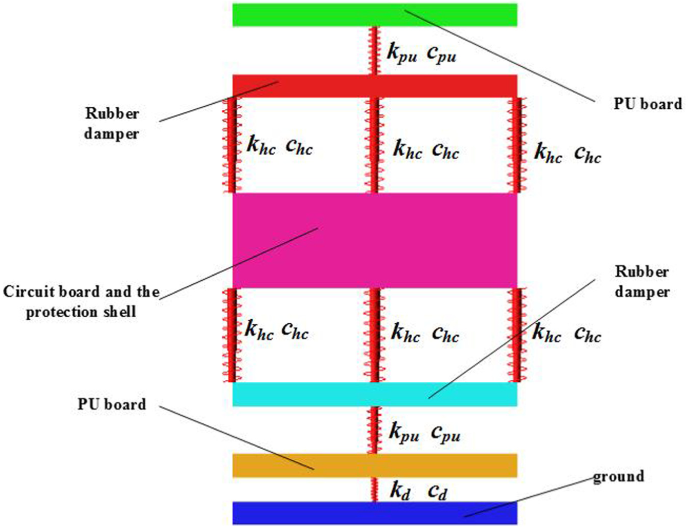
Model of a spring absorber system under free impact.
Taking the node protection shell and the circuit boards as a whole, we determine the elastic and damping coefficients of both the PU board and the rubber shock absorber. Here, we utilize the approximation method; according to the definition of the elastic modulus, the elastic coefficient of material is given by

where k denotes the elastic coefficient of the material, L denotes the thickness of the material, and S denotes the cross-sectional area in the thickness direction.
Each PU board has the following parameters: elastic modulus Epu = 18 MPa, thickness lpu = 20 mm, and weight mpu = 0.96 kg. There are three types of cross-sectional areas because of the three specifications of PU board. In this part, we consider the free impact condition when the largest surface of the protection device hits against the ground squarely, with the other conditions being the same as in theory. The cross-sectional area of the PU board Spu is 4 × 104 mm2. According to equation (2), we can obtain that kpu is 3.6 × 10⁴ N/mm. According to Song et al., 18 cpu, the damping coefficient of the PU board, is 1.8 N s/mm in this article.
For the rubber damper, Ehc, the elastic modulus, is 8 MPa. The thickness of the rubber damper, lhc, is 15 mm. The weight of the rubber damper, mhc, is 0.01 kg. The rubber damper’s cross section is a circle, and the area of this circle Shc is 100 π mm2. Therefore, through calculation, khc is 125.6 N/mm. The main component of the rubber damper is natural rubber. According to Romero and Martin, 19 chc, the damping coefficient of the rubber damper, is 0.05 N s/mm in this article.
For node circuit boards and the protective shell, the total weight mnd = 2 kg.
For the elastic coefficient kd and the damping coefficient, cd, between the node protection device and the ground, the relationship is kd > kpu and cd > cpu.
The parameters of (1) the instantaneous speed of the impact, (2) the weight of the PU board, (3) the elastic coefficient and the damping coefficient of the PU board and rubber damper, (4) the weight of rubber damper, and (5) the total weight of the circuit boards and the protection shell should be imported into ADAMS to simulate the process of the impact of the circuit boards. Figure 4 shows the displacement, velocity, and acceleration of the node circuit boards during the impact progress obtained from the simulation.

(a) The displacement, (b) the velocity, and (c) the acceleration of the node circuit boards during the impact progress.
As is shown in Figure 4, the maximum amplitude of the circuit boards is 23 mm. The oscillation time is approximately 400 ms, and the oscillating attenuation is rapid. The first derivative of the displacement is the speed, and the initial speed is −8.854 m/s. The maximum acceleration can reach 2300 m/s2. According to these data, we can conclude that our circuit boards can survive the free-fall impact because of the rapid vibration attenuation, small displacement, and the short time of the impact despite the instantaneous shock force being large.
Analysis of tunnel collapse
The impact cushioning device should be installed on top or on the sidewalls of the tunnel because of the special underground geographical environment. As shown in Figure 5, if the tunnel collapses, then the impact cushioning device will fall to the ground. The relative position between the device and ground is uncertain because of the complex conditions after the catastrophe.

Schematic of impact cushioning devices during tunnel collapse.
Under the circumstance of an uncertain relative position, the protection device might have to bear the impact caused by the falling rocks from the top or the sidewalls of the tunnel. Transient dynamics theory can be used to simulate and analyze this type of instantaneous impact. The flowchart of the solution of the collision model is shown in Figure 6.

Solution flowchart of the rock and impact cushioning device collision model.
The shapes of the falling rocks change as the tunnel collapses. To simplify the solution process, we must simplify the rock model. We take each rock as having an approximately rectangular cross section. The basic parameters of the rock model are shown in Table 2.
The basic parameter table of rock model.

As the geometric size of the impact cushioning device was described above, the material properties of the device will be mainly discussed in this part. Rubber and plastic are two main material of our device. The PU board, rubber damper, and natural rubber block are made out rubber. The ABS box and circuit boards are made out plastic.
For rubber materials, the Mooney–Rivlin model is always adopted in the large-strain problems. C01 and C02 are two mechanical parameters of this model, and they can be obtained from related experiments. The experiments, such as uniaxial tension, plane shear, and biaxial tension, which are too complex to model, 20 must be performed to obtain more accurate performance parameters. For the PU board, C01 is 0.105 and C02 is 2.101 in this article, according to engineering experience. For the rubber material, C01 is 0.35 and C02 is 0.47. For the plastic material, the ABS box and circuit boards are made of plastic. The main component of the ABS material is acrylonitrile butadiene styrene. The main components of the circuit boards are resin, reinforcing material, and copper foil. The material attributes are shown in Table 3.
The material attributes of the node.

PU: polyurethane; ABS: acrylonitrile butadiene styrene.
To simplify the model, we divide the position of the node into three special cases and three arbitrary cases (shown in Figure 7): standing on the ground, side standing on the ground, headstand on the ground, and the other three cases of the three orthogonal surfaces touched the ground in arbitrary postures (45° is considered in this article).
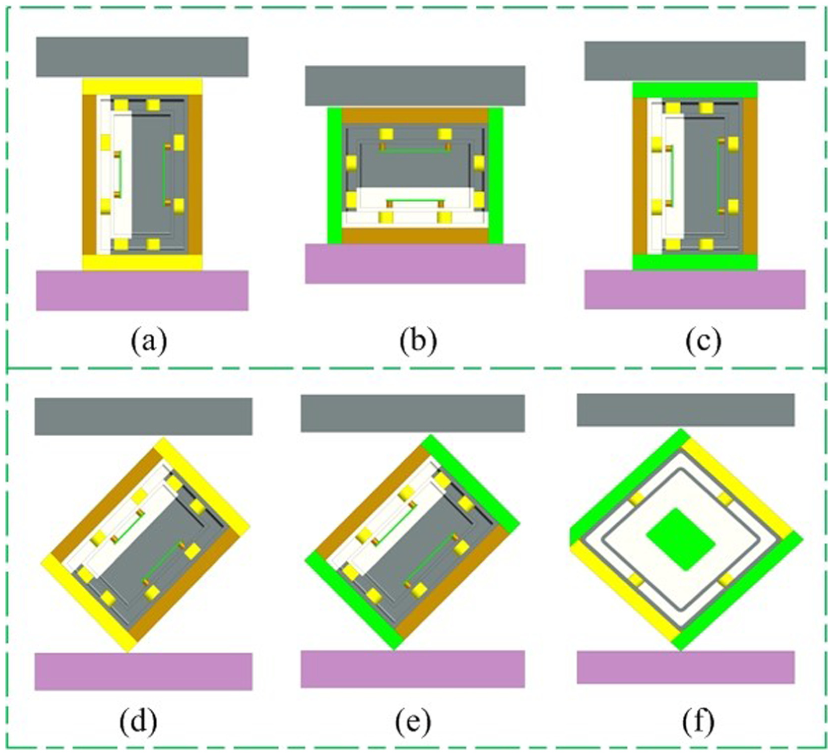
Position and orientation graphing of node protector under tunnel collapse: (a) the front shell, (b) the side shell, (c) the top shell, (d) the intersection of the front shell and the side shell, (e) the intersection of the front shell and the top shell, and (f) the intersection of the top shell and the side shell.
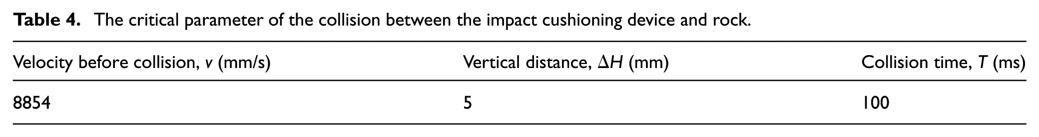
The vertical distance between the rock and the impact cushioning device, the speed of the rock, and the collision time are important critical parameters before the collision. The software ANSYS LS-DYNA is mainly used to analyze transient dynamics. Software analysis will be slow if the collision time is too long. As a result, we start our analyses at the brief period before the collision to determine the result of an instantaneous collision. The speed when the rock falls freely from the top of the tunnel to the ground is the maximum speed of the rock before the collision. Because the height of the tunnel is 4 m, we can determine that v, the speed of rock before collision, is 8854 mm/s. We assume that ΔH, the distance between the rock and the impact cushioning device, is 5 mm. The collision time T satisfies

The calculated critical parameters before the collision between the rock and the device are shown in Table 4.
The critical parameter of the collision between the impact cushioning device and rock.
A geometric model should be established in Pro/E software before we perform analysis in ANSYS LS-DYNA. First, import the model into the Explicit Dynamics module in ANSYS. Second, define the material properties and set up the contact interfaces. The material properties have been provided above. The attributes of the contact interfaces should all be set as bond. Third, mesh the model. Fourth, input the critical parameters into the Explicit Dynamics module and define constraints and boundary conditions. Finally, determine the distribution of stress.
The stress distribution at different positions is shown in Figure 8. The maximum stress is focused on the shell of the ABS box during the collision.
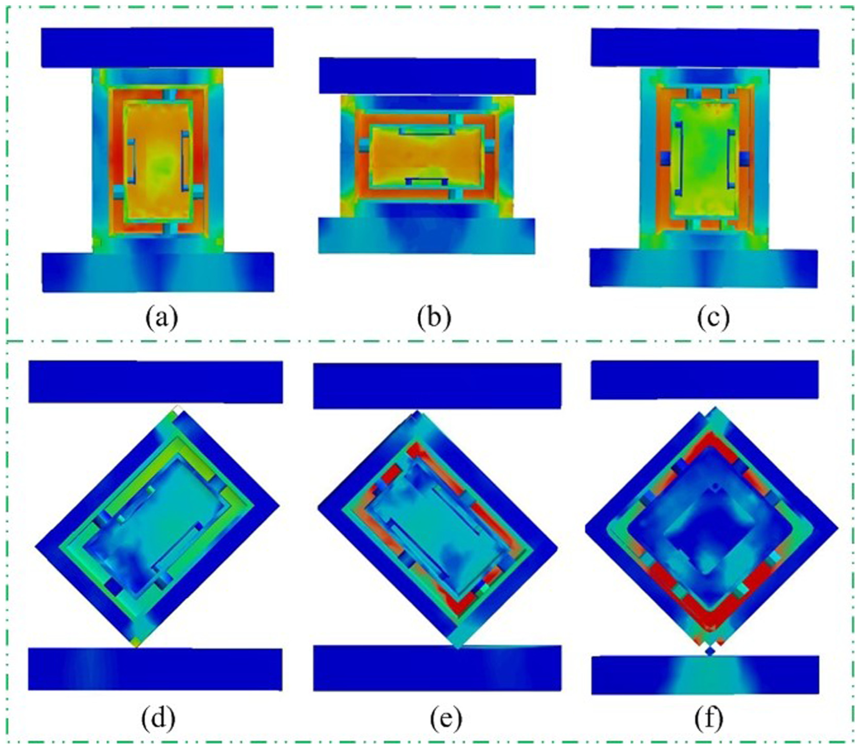
Stress distribution of the collision under tunnel collapse: (a) the front shell, (b) the side shell, (c) the top shell, (d) the intersection of the front shell and the side shell, (e) the intersection of the front shell and the top shell, and (f) the intersection of the top shell and the side shell.
The stresses of the ABS plastic box at different positions are shown in Figure 9. During the shock time of 100 ms, the maximum stress of the device presents a linear increase, followed by oscillating attenuation. The difference is that the positions (a), (b), and (c) reach the first peak stress value in the range of 65–75 ms, and the first peak stress value is the maximum value, followed by a relatively stable oscillating attenuation. The stress value of positions (d), (e), and (f) reach the first peak stress value earlier than positions (a), (b), and (c), before 40 ms, followed by oscillating attenuation with a large amplitude and high frequency, and the stress value of positions (e) and (f) reaches the maximum during the oscillation. We know from Figure 9 that the stress value of the impact cushioning device is always less than 90 MPa during the collision process, and the yield strength of the ABS box is 225 MPa, which is much higher than the maximum stress of the impact cushioning device. In addition, the collision time is extremely short. As a result, the ABS plastic box can survive a tunnel collapse.

Stress of the ABS plastic box during the collision under tunnel collapse.
The previous analysis proved that the impact cushioning device can resist the tunnel collapse impact; however, we must design the impact cushioning device to protect the sensor node from damage when a disaster occurs. Therefore, we analyze the stress of the circuit board in the following. The stresses of the circuit boards during the collision are shown in Figure 10. During the shock time of 100 ms, the stress value of the positions (a), (b), and (c) presents oscillation with a higher frequency after 40 ms, and the positions (d), (e), and (f) show a linear increase before 60 ms, followed by oscillating attenuation with a low frequency and large amplitude. The maximum stress is less than 10 MPa, and the yield strength of the printed circuit board (PCB) boards is 200 MPa. As a result, the circuit board is safe during the collision.

Stress of the circuit board during the collision under tunnel collapse.
Stress analyses of the circuit boards and the ABS plastic box of impact cushioning device during the collision between the rocks and the device were performed to prove that the sensor node can survive a tunnel collapse under the protection of our impact cushioning device. Thus, the sensor node can provide accurate environmental information underground and save precious rescue time after a disaster, thereby greatly enhancing the ability of emergency rescue efforts.
Analysis of the gas explosion
A gas explosion is a chain reaction caused by intense oxidation of methane and oxygen. A gas explosion is one of the severe disasters that occur in underground coal mine production. 21
The peak pressures of the shock wave caused a gas explosion range from several atmospheric pressures to 20 atmospheric pressures. The superposition and the reflection of the forward shock wave will greatly increase the pressure to 100 atmospheric pressures. Two types of pressure will be produced during the gas explosion: static pressure and shock dynamic pressure. The force caused by the static pressure is equal in all directions because of the high-temperature gas expansion and the gas flowing along the tunnel, and the static pressure will promote the advance of the wave surface. The shock wave will lead to a high-velocity flow of air flow via the wave surface, which will form the dynamic pressure. Dynamic pressure is directional. Static pressure will break the airtight seal of the cushioning device by destroying the air door. Dynamic pressure will destroy the obstacles in the tunnel and cause great damage in the corner. The propagation velocity of the shock wave is faster than sound. Casualties, equipment damage, and tunnel collapse will be caused by the shock wave.
Impact cushioning devices may fall from the tunnel or remain fixed on the wall during a gas explosion. The gas explosion will lead to a fierce collision among the impact cushioning device, the sidewall, the coal rock, and the ground. To simplify the model, we take the tunnel wall, coal rock, and the ground as rocks. The relative position between the device and the sidewall, coal rock, or the ground is uncertain. Similar to the analysis of the tunnel collapse, the collision model of a gas explosion should be established. The relative positions of the impact cushioning device are shown in Figure 11.

Position and orientation graphing of node protector under gas explosion: (a) the front shell, (b) the side shell, (c) the top shell, (d) the intersection of the front shell and the side shell, (e) the intersection of the front shell and the top shell, and (f) the intersection of the top shell and the side shell.
The steps for solving the gas explosion model are similar to those of the tunnel collapse model; however, the critical parameters before the collision are different. A gas explosion can produce a millisecond load. The characteristics of the load are short time and high strength. At present, a triangular wave is always used to simulate the shock wave. We assume that the load of the explosion shock wave increases from 0 to the maximum in 3 ms and then decays to 0 in another 3 ms. The maximum pressure produced by the gas explosion is 2 MPa, and we take it as the maximum load. The time–pressure loading curve is shown in Figure 12.

Plot of the shock pressure under gas explosion.
The stress distributions for different orientations are shown in Figure 13. The maximum stress is focused on the shell of the ABS box during the collision.

Stress distribution of the collision under gas explosion: (a) the front shell, (b) the side shell, (c) the top shell, (d) the intersection of the front shell and the side shell, (e) the intersection of the front shell and the top shell, and (f) the intersection of the top shell and the side shell.
The stresses of the ABS plastic box at different positions for different orientations are shown in Figure 14. During the 100-ms shock time, the maximum stress of the device presents a linear increase, followed by an oscillating attenuation. The maximum stress values at positions (a), (b), and (c) are below 40 MPa, and those at positions (d), (e), and (f) are higher than 80 MPa. The attenuation extent of positions (a), (b), and (c) is small, but the stress values of positions (d), (e), and (f) decay faster than positions (a), (b), and (c) and reach a smaller value quickly. The yield strength of the ABS box is 225 MPa, which is much higher than the maximum stress of the impact cushioning device. In addition, the collision time is extremely short. As a result, the ABS plastic box can survive a gas explosion.

Stress of the ABS plastic box during the collision under gas explosion.
The previous analysis proved that the ABS plastic box can survive a gas explosion. Next, we analyze the stress of the circuit boards. The stresses of the circuit boards during the gas explosion are shown in Figure 15. During the shock time of 100 ms, the stress of the boards exhibit a linear increase, followed by oscillating attenuation at high frequency. The difference is that positions (a), (b), and (c) reach the first peak stress value close to 40 ms, whereas positions (d), (e), and (f) reach the peak at nearly 60 ms. The maximum stress of the second PCB is larger than the first PCB in positions (a), (b), (c), (d), and (e), and all of them are less than 10 MPa under the six positions. The yield strength of the PCB boards is 200 MPa, and the collision time is extremely short, so the circuit boards are safe during the gas explosion.

Stress of circuit board during the collision under gas explosion.
Conclusion
An impact cushioning device is a prerequisite to ensure the efficient communication of a monitoring network used in the poor geographical conditions and uncertain factors of an underground coal mine. The impact cushioning device introduced in this article can not only meet the material requirements of coal mine equipment but also ensure the communication quality. After establishing a simplified model of the practical conditions and using it to perform simulations, we arrive at the following conclusions:
The circuit boards can survive a free-fall impact because of the rapid vibration attenuation, small displacement, and the extremely short impact time, despite the large force at the instantaneous impact.
The sensor impact cushioning device will collide with the scattered rocks when the tunnel collapses. The maximum stress focuses on the shell of the ABS box during the collision. In 100 ms of shock time, the maximum stress of the ABS presents a linear increase, followed by an oscillating attenuation. The yield strength of the ABS is 225 MPa, which is much higher than the maximum stress of the impact cushioning device. The maximum stress of the circuit boards is less than 10 MPa. In addition, the collision time is extremely short. As a result, the device can survive a tunnel collapse.
The sensor node will collide with the sidewall fiercely because of the shock wave caused by a gas explosion. The maximum stress focuses on the shell of the ABS box during the collision. The maximum stress of the ABS presents a linear increase followed by oscillating attenuation. The maximum stress is much less than the yield strength of the ABS box, and the maximum stress of the circuit boards is less than 10 MPa. The collision time is extremely short. As a result, the device can survive a gas explosion.
Footnotes
Handling Editor: Farzad Ebrahimi
Declaration of conflicting interests
The author(s) declared no potential conflicts of interest with respect to the research, authorship, and/or publication of this article.
Funding
The author(s) disclosed receipt of the following financial support for the research, authorship, and/or publication of this article: This work is supported by the National Key Research and Development Program (No. 2016YFC0600905), the Jiangsu Provincial Natural Science Foundation of China (No. BK20151146), the National Natural Science Foundation of China (No. 51575513), the Fundamental Research Funds for the Central Universities (No. 2014QNB20), and a project funded by the Priority Academic Program Development of Jiangsu Higher Education Institutions (PAPD).