
Abstract
This paper presents a novel double-direction inchworm in-pipe robot, called the Cam-Linkage Robot (CLR), used to carry sensors and instruments to perform inspection and cleaning jobs inside pipelines. The prototype has been developed to improve the driving ability and reduce the difficulty of control. CLR is suitable for pipe diameters from 360 mm to 400 mm due to its functions of manual adjustment and automatic adaptation. The structure of CLR was presented and some critical design issues on the principle of cam-linkage mechanism were discussed. Based on cam-linkage mechanism, CLR could press the wall actively and creep in two directions via only one motor, so this research has broken the limitation that traditional active wall-press robot needs more than one actuator. The cam pressure angle could be reduced to 0, and the propulsion ability was almost not weakened by the support motion at the stable support stage. Finally, experiments were conducted to validate the locomotion principle and the effectiveness of CLR.
Introduction
Pipelines are widely used in water, oils, gases and solid particles transportation. Recently, some damage and jam appear in the pipelines, such as corrosion, blocking, and cracks. Currently, in-pipe robots are considered as one of the most attractive equipment for the pipeline inspection, maintenance, and cleaning.1,2 In addition, wet pipes will reduce the insulation of the circuit board and cause short circuit. 3 Such applications require a simple control method and sufficient traction ability to pull or push some heavy service instruments, but recently presented active wall-press robot have more than one actuator, and multi-actuators will increase the control difficulty of the robot.
The in-pipe robot system, according to existing moving modes and contact forms with pipe wall, can be classified into several classical forms, including pig type,4–6 wheel type,7–10 wall-press type,11–13 walking type,14,15 screw type,16–21 inchworm type,22–25 and swimming type.26,27
The wall-press robots, suitable for walking in circular pipes, have three sets of wheels or legs circularly located 120° apart from each other. 28 They are not applicable to pipes with rectangular section, such as U-shaped groove or square pipes. Unfortunately, due to the active wheels always firmly press the wall during the move, their forward resistance will increase with increasing support force when the wall is not flat, thus, the energy consumption increases.
The self-lock inchworm robots take full advantage of the force produced by wedges between the robot and inner pipe wall. 1 The locking force mainly depends on the permanent magnetic force and the inclination angle of wedges. However, the locking-release force will go up with the increasing permanent magnetic force. Additionally, the robot can only walk in one direction because the inclined direction of wedges has been determined beforehand, unless an additional driver is added to change the direction of the wedge, which increases the complexity of the mechanism and control. To improve the flexibility of robots, a multi degree of freedom peristaltic robot has been developed, 22 which is composed of two symmetrically arranged 3-RPS parallel mechanisms and a single degree of freedom extensible platform. The robot has many degrees of freedom, and can adapt to complex terrain, but its structure and control are very complex.
In the field of micro pipeline, worm-like soft robot has been developed. 29 The robot is completely soft, and consists of one multidegree of freedom (DoF) extension module and two clampers for locomotion and steering. The multi-DoF extension module is able to adjust the heading direction in the three-dimensional space. The clamper has a basic expansion module structure and detachable sucking module structure. The combined clamping principle for sticking to the inner wall can be reconfigurable to adapt the tubes with multiple tubular scales and super elastic materials. A pneumatic peristaltic robot is proposed. 30 The robot can produce driving force and holding force, and the robot can produce longer stroke and higher speed. The in-pipe robot achieves rapid locomotion through narrow pipes by a unique duplex-chambered structure. The mechanism achieves smooth bi-directional inchworm locomotion by a combination of expandable silicone rubber and a coil spring and is fully controlled by only two air supply lines.31,32 However, the robot needs to be connected to a complex compressed gas source, which makes the application inconvenient. A telescopic pipeline robot is proposed. 33 The robot can achieve orderly telescopic movement through a camshaft. However, the telescopic leg of the robot does not have the active telescopic ability. During walking, it continuously rubs against the pipe wall to accelerate the wear of the robot’s contact leg.
We are presenting a cam-linkage inchworm in-pipe robot, called CLR, to break out the aforementioned limitations, and improve the traction ability by using a symmetric cam mechanism. It can realize active support to the pipe wall and double-direction creep via only one motor. The cam-linkage mechanism, which is the core mechanism of the CLR, is explained in detail in the following section. In addition, the mechanical designs of CLR are explained, and the results of experiments are discussed.
Structure description
As shown in Figure 1(a), the proposed CLR is mainly made up of two parts: Front body and rear body. Figure 1(b) shows that CLR consists of three functional module: two supporting mechanisms at two ends, one propulsion mechanism in the middle acting as the driver. The propulsion mechanism is mainly made up of motor, sliding-rotating mechanism, and cam-linkage mechanism, used to connect the front and rear supporting mechanisms.

Cam-linkage robot (CLR): (a) assembly drawing of CLR and (b) exploded view of CLR.
Supporting mechanism
The supporting mechanism is the action part of the front and rear bodies, used to generate force and form closures with pipelines. 34 As depicted in Figure 2(a), the supporting mechanism is mainly composed of two supporting legs and two supporting wheels. The supporting legs are driven by the cam group and then reset by spring 1 to realize the active support to the wall. In Figure 2(b), the length of the supporting leg could be adjusted manually through the screw to adapt to pipes with different diameters. When the screw is screwed, the relative distance between the part 1 and part 2 is determined. Part 3 could slide relative to part 2 and compress the spring 2, thus producing the support force to pipe wall. In Figure 2(c). The supporting wheel is equipped with spring 3 to adapt to small changes in the diameter of the pipe.

Constructions of (a) supporting mechanism, (b) supporting leg, and (c) supporting wheel.
Cam-linkage mechanism
As shown in Figure 3(a), cam-linkage mechanism (CLM) mainly made up of three part, two cam groups, and one linkage, with the output of stretching out and drawing back, the cam mechanism realizes the support and contraction to the pipe wall, and the linkage mechanism realizes stretching and shortening motion between the front and rear bodies. The cam group, bevel gear, and the crank are fixed together for synchronous rotation.

Propulsion mechanism of CLR: (a) cam-linkage mechanism and (b) sliding-rotating mechanism.
Sliding-rotating mechanism
The sliding-rotating mechanism (SRM) consists of two parts. As shown in Figure 3(b), the part 1 is fitted with a pin and bevel gear. The sliding bush of the part 2 has a sliding chute. So when the part 2 turns, the part 1 rotates synchronously with the part 2, and the part1 could slide freely relative to the part 2. Sliding-rotating mechanism is powered by the motor, and transfer the power to the front cam group and the rear cam group. The front and rear cam groups are rotated synchronously, and the rotation direction of the two is opposite.
Motivations
Principle of transmission and movement of CLR is shown in Figure 4, the cam is used to drive the leg for expansion motion. The crank can be rotated continuously, and the relative expansion motion between the two bodies is driven by the linkage, so CLR can move in an orderly way.

Locomotion principle of CLR: (a) principle of transmission and (b) principle of two-way movement.
Principle of CLR
As shown in Figure 4(a), the stepper motor passes the power to the bevel gear through the SRM, and the deceleration ratio of the reducer and bevel gear is 15:1 and 2:1, respectively. Through the coordination of the cam and the linkage mechanism, CLR can make peristaltic walk. As illustrated in Figure 4(b), the moving direction of CLR is changed by changing the rotation direction of cam.
Design of cam profile
As shown in Figure 5. The outline of the cam consists of two circular arcs with radius of R1 and R2, and a composite curve for connecting two circular arcs. When the cam roller contacts the circular arc R1 or R2, the supporting mechanism remains stationary (far rest, near rest).
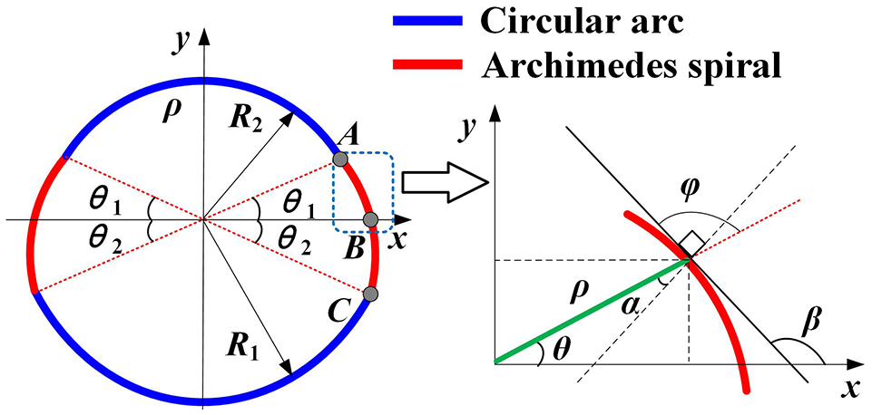
Cam outline curve of CLR.
In order to eliminate the rigid impact caused by constant speed movement, the roller of the follower must be corrected to keep normal contact with the cam profile. The polar coordinate equation of the cam profile is as follows:

If pressure angle of the cam mechanism is too large, it will cause the self-locking of the cam. So it is necessary to calculate the pressure angle of cam mechanism. The pressure angle of the circular arc part is equal to zero, and the parametric equation of the Archimedes spiral part is as follows:

Through the derivation of (2), tangent of β is obtained as follows:

As the outer angle of a triangle is equal to the sum of the adjacent angles, the tangent of φ is obtained as follows:

Substituting (3) to (4), the result can be simplified as follows:

Solving (5) yields:

By geometric relation, the pressure angel is obtained as follows:
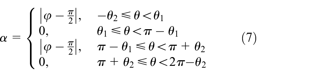
From (1), (6), and (7), specific expression of the pressure angle is obtained:

Equation (8) indicates that the pressure angle of the circular arc part is 0, which means the cam mechanism can realize the reverse-locking and the rotating resistance is very small. As (R1θ1 + R2θ2) is a constant, the pressure angle α decreases with the decrease of (R1–R2). This shows that when the diameter of the pipe is determined and not changed, R1 should be as close to R2 as possible, and beneficial to obtain greater support force to the wall.
Analysis of supporting motion
In Table 1, two kinds of cams are put forward based on different θ2. When θ2 is equal to 0, the cam type is defined as CAM I. When θ2 is greater than 0, the cam type is defined as CAM II.
Two kinds of cams.
As shown in Figure 6, the pressure angle gradually decreases as the leg is extended. It can be seen that the pressure angle α is always less than the allowable value of 35°, and it will not cause self-locking. Large moving distance of cam follower will lead to large pressure angle and poor effect of transferring force, so CLR is mainly applicable to equal diameter pipe or pipe with small diameter change; if it is necessary to detect other diameter pipe, the length of leg can be adjusted manually in advance.

Pressure angle of CAM I and CAM II.
Due to the need of detection and maintenance, the walking speed of CLR is not high, so Archimedes cam is used to make the legs stretch at a constant speed. If a high-speed robot needs to be designed, the cam curve with combined motion law or high-order polynomial can be used. As shown in (9), A, B, C are three points on the Archimedes spiral line, meeting the following conditions:

From Figure 7, steady state means legs of the front body (or rear body) keeps in full contact with pipe wall (the leg is completely compressed), while another body’s legs have no contact with the pipe wall (the leg is not compressed), and the rest belongs to dynamic state. The pre compressed springs can make the robot produce enough contact force between the pipes.

Analysis of motion state: (a) spring compression state, (b) leg telescopic change, and (c) motion principle of robot.
From state 1 in Figure 7(c), when the angle of crank BC is 0, the leg force of FB and RB on the pipe wall is equal, but at this time, slider A has not moved; From state 2, the crank BC continues to rotate, when the leg of FB loses contact with the pipe wall, at this time, the leg force of FB on the pipe wall suddenly changes to 0, The contact force of RB increases, so that RB remains stationary and FB moves to the left. RB and FB alternately squeeze the tube wall, so the robot can keep walking forward and avoid slipping.
Analysis of driving force and speed
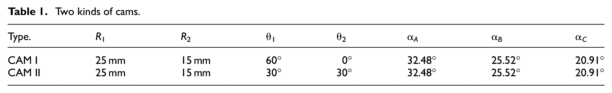
To reduce the computational complexity, it is assumed that the friction between the parts is small enough, the effect of gravity and the roller radius of cam is ignored, and the cam is rotated at a constant speed. The force analysis is carried out in Figures 8 and 9.
Simplified force for cam mechanism.

Simplified force for Crank slider mechanism.
Force analysis of cam mechanism

Where Fn is the support force to the wall, Ff is the friction between the wall and the supporting legs, T0 is component of torque, μ is the friction coefficient between CLR and the wall. Solving (10) yields:
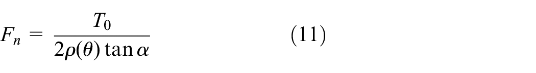
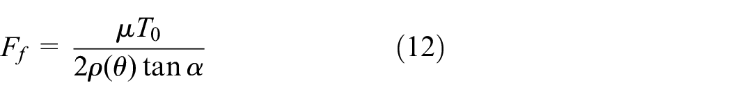
Equation (12) shows that when the torque T0 and polar radius ρ(θ) are certain, the smaller the pressure angle α, the greater the driving force Ff. In the process of turning from point A to point C, the polar radius ρ(θ) gradually increases, but the pressure angle gradually decreases, thus the influence of the ρ(θ) is weakened.
Force analysis of crank-slider mechanism

According to the sine theorem and theorem on moment of resultant force:


Where F is the propulsion force, T is the Total torque after deceleration, T1 is the component of torque.
Solving (13) yields

Substituting (11) and (15) to (16)

The driving force depends on the supporting force Fn, friction coefficient μ, and the propulsion force F of the propulsion mechanism. The approximate interaction between the two forces is shown in equation (17), for the specific parameters depend on the actual conditions, the final driving force of the robot is obtained through experiments.
Average speed of walking
As shown in Figures 4 and 9, the cam rotates a circle, CLR moves forward a certain distance that equal to 2 times the length of the crank, so the average speed of the robot is obtained as follows.

Where ω is the rotational speed of the motor, L2 is the crank length, i represents the transmission ratio of motor and cam. This shows that the higher the speed of the motor, the greater the crank length, and the smaller the deceleration ratio, the faster the moving speed of the robot.
Experiments
Prototype
As shown in Figure 10, the experiments described previously were all performed on the prototype with different conditions. Based on manual adjustment and automatic adaptation, CLR is suitable for pipe diameters from 360 to 400 mm. CLR is designed to be applied to horizontal pipeline inspection, so the test is carried out in a horizontal pipe and U groove.

Prototype of CLR.
Test system
Testing system was specially built to test the performance of CLR. CP1H-XA40DT series PLC is selected as the controller, with compact structure, 40 input and output points in total, including 24 output points. The analog output of the sensor can be read by analog input module, and then the robot load pull value can be obtained by AD conversion. In addition, the PLC has the function of high-speed pulse output, which can connect stepper motors or servo motors, and can control the rotation speed and direction of motors. The control system and motor driver are powered by switching power, which converts 220 V AC to DC, of which 48 V DC voltage supplies power to motor driver, and 24 V DC voltage supplies power to PLC. Their mutual relationships are shown in Figure 11. The test platform was assembled to create different testing environments. The touch screen is used to adjust the motor speed and control the robot forward and backward. The test platform has three main functions:
Set different roll angles;
Set different rotational speeds;
Provide different motion space (circular pipes and U grooves).

Test system.
Results and discussions
Finally, we measured the driving force of CLR in various conditions using a cable and tension sensor. In Figure 12, due to the use of four point support to the wall, CLR can walk forward and backward in a horizontal circular pipe and U groove. The motor passes the power to the cam after deceleration. Figure 13 shows that the robot was carrying its maximum payload of 160 N. This indicates that the driving force is not affected by the rolling speed when the cam speed is less than rated speed, 40 r/min, and almost not affected by the roll angles.

Experiments for driving ability in transparent pipe and U groove.

Propulsion force with different velocities and roll angles.
In Table 2, Compared with several other robots, CLR has greater driving force and could get a two-way creeping walk via only one driver. In addition, CLR has a smaller ratio of length to diameter.
Previous work results comparison.

Conclusion
This paper mainly presents a novel in-pipe robot, called CLR. It could creep forward and backward in a circular pipe and U groove through a motor. This characteristic improves the efficiency of motor utilization and reduce the difficulty of control, and some simple but effective arguments on CLR have been presented.
The cam-linkage mechanism is introduced to help the in-pipe robot obtain an inchworm and active support motion by only one actuator.
The cam pressure angle could be reduced to 0, and the propulsion ability was almost not weakened by the support motion at the stable support stage.
For the symmetrical cam groups and crank can turn in both directions, so this research has broken the limitation that traditional inchworm in-pipe robot cannot walk in two direction via only one actuator.
(4) The results of this paper can be used to reduce the number of drivers and improve the traction ability of the inchworm in-pipe robot, and as guidelines for designing this type of robots.
Footnotes
Handling Editor: James Baldwin
Declaration of conflicting interests
The author(s) declared no potential conflicts of interest with respect to the research, authorship, and/or publication of this article.
Funding
The author(s) disclosed receipt of the following financial support for the research, authorship, and/or publication of this article: This work was supported by Initial Scientific Research Fun in Xuzhou University of Technology (02900199), Xuzhou science and technology project (KC18149), the Top-notch Academic Programs Project of Jiangsu Higher Education Institutions (TAPP), and the Priority Academic Program Development of Jiangsu Higher Education Institutions (PAPD).