
Abstract
Dual-arm robot Baxter has been utilized in many applications. To use the Baxter robot realize a peg-in-hole assembly task, we proposed a step-by-step grasping strategy and a vision-guidance method for the Baxter robot. The step-by-step grasping strategy was used to position and grasp a peg and a hole on the working platform. At the assembling process, the positioning error was derived by the camera attached on the robot end-effector, and the positioning error was compensated through proportional–integral–derivative controller. Experiments were conducted to evaluate the grasping strategy and the vision-guidance method. Experimental results show that the Baxter robot can grasp the peg and the hole from the working platform, and the peg in hole with 1 mm clearance can be assembled successfully.
Introduction
Similar to the dual arm of human being, a dual-arm robot can control the relative motion and interaction of assembly counterparts in a human-like manner. Due to this characteristic, dual-arm robots have been focused by many robotic companies and researchers. There are many dual-arm robots applied in varied industrial tasks, such as assembly task and pick-and-place task.1–3 Recently, several types of dual-arm robots, such as Baxter robot, 4 YUMI robot, 5 and NEXTAGE robot, 6 have been widely applied in the industrial field, especially for the assembly task. Normally, the accuracy of assembly can be improved using precise hardware of robot or based on some soft technologies including sensing, controlling, planning, and programming. However, a dual-arm robot with precise hardware is of high cost. Therefore, it is important to improve the accuracy of assembly for dual-arm robot based on some soft technology.
In previous studies, many researchers focused on the assembly strategies and control methods to make robots complete an assembly task. Most assembly strategies are developed with the robot control methods. The robot control methods can be categorized into three classes: 7 position control, force control, and hybrid position/force control. Using the position control method for a robot to complete an assembly task, vision sensor is commonly used to obtain the relative positions and orientation of assembly units.8–11 In Korta et al., 9 a vision system based on OpenCV libraries was proposed for an industrial robot-based assembly station to realize the electronic circuit assembly. The position and orientation of an item was derived by the vision system. A visual sensing system was proposed to measure the deformation and misalignment of a part in a deformable cylindrical peg-in-hole task. 10 In Lin et al., 11 a vision-based pose estimation was proposed to locate the peg and the hole in the workspace of an industrial robot. Using force control or hybrid position/force control method for a robot to complete an assembly task, force sensor is commonly used to obtain the interaction force of assembly units.12–15 In Patel et al., 12 an outer-inner loop controller with robust position and contact force control was proposed for 7-degree-of-freedom (DOF) redundant robot arms. In the literature,13,14 information from force sensors was used to guide the motion of robot. While in Lee and Asada, 15 a control strategy for force guided assembly was proposed based on the interpretation of measured force acting on the robot end-effector. Instead of measuring contact forces directly, some perturbation was given to the end-effector to obtain more information to the reaction forces. In some other studies, compliant devices and compliance control were applied to robots to realize an assembly task.16–18
Baxter robot is a dual-arm robot with sonar and camera sensor, which has been focused by many researchers due to its collaboration with human being.19–23 However, the positioning accuracy of Baxter robot is low because the accuracy of hardware used in the robot is low and the serial elastic actuator (SEA) is used for each joint. 4 The low positioning accuracy limits the application of Baxter robot. At this stage, Baxter robot is capable of following tasks: material handling, machine tending, testing and sorting, light assembly, and finishing operations. To apply the Baxter robot for other tasks like assembly task, the positioning accuracy of Baxter robot needs to be improved. Therefore, we aim to improve the positioning accuracy of Baxter robot to complete a peg-in-hole assembly task in this article. We first position the assembly unit based on monocular vision method and propose a step-by-step strategy to grasp the assembly units. Then, we calculate the relative position error of assembly units grasped by each arm based on perspective-n-point (PnP) measurement method and guide the robot arm to complete the assembly task by compensating the relative position error with proportional–integral–derivative (PID) control. The contribution of this article is that we propose a vision-guided method for Baxter robot to improve the assembly accuracy, which can enhance the applications of Baxter robot.
The remaining parts of this article are organized as follows. The second section is the problem formulation. The proposed method is described in section “Proposed approach.” In section “Experiment,” the experiment, results, and discussion are presented, and the last section provides the conclusion.
Problem formulation
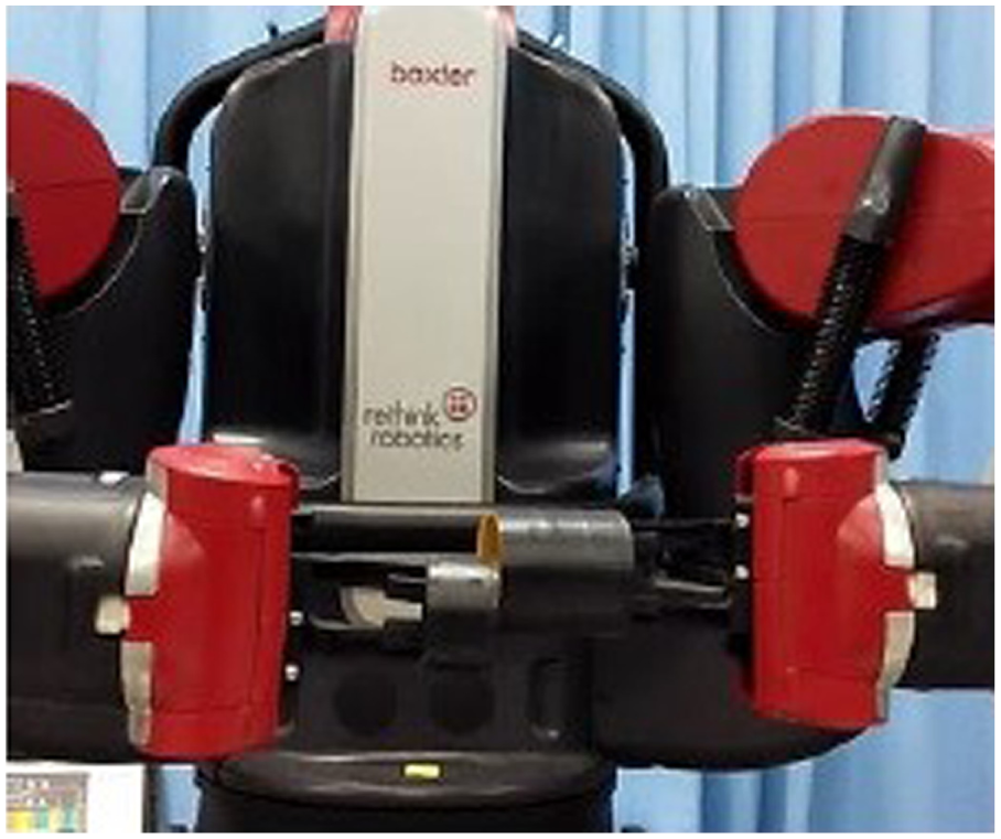
This section describes the problem of vision-guided peg-in-hole assembly. Baxter robot is considered as a research platform and is used to complete a peg-in-hole assembly task, as shown in Figure 1. First, the robot positions the assembly units (i.e. peg and hole) on the worktable. Second, one arm grasps the peg, and another one grasps the hole. Third, two arms approach each other and inserts the peg into the hole. To realize the peg-in-hole assembly, the peg and hole on the worktable should be positioned and grasped accurately, and the relative position and orientation error of assembly units should be compensated when the peg is inserting into the hole.

A peg-in-hole assembly task completed by Baxter robot.
Baxter robot is a dual-arm robot with 7 DOFs in each arm. The robot is developed based on Robot Operation System (ROS), and the kinematic model is described by Unified Robot Description Format (URDF) file. The next frame is obtained by the transformation of previous frame in the three-coordinate axis, as shown in Figure 2. The torque is transmitted from actuator to joint through torsional spring at each joint, which makes Baxter robot be safe but results in low positioning accuracy. To improve the performance of Baxter robot, several sensors are used in the robot. As shown in Figure 1, Baxter robot has two camera sensors attached on the end-effector of each arm. In this article, we use the camera sensors attached on the end-effector to obtain the information of assembly units. The Baxter robot can be considered as an eye-in-hand system.
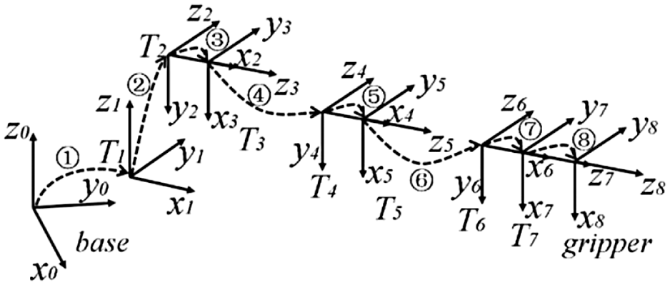
The frames of Baxter’s arm.
Proposed approach
Overview of the proposed approach
In this article, we proposed a vision-based method to realize the peg and the hole positioning, grasping, and peg-in-hole assembly, as shown in Figure 3. Because the camera was attached on the end-effector of the robot arm, we considered the camera system as an eye-in-hand system and calibrated the eye-in-hand system. Due to the hardware of Baxter robot, the positioning accuracy of Baxter robot is low. To accurately position and grasp the peg and hole on the worktable, we proposed a step-by-step object grasping strategy. After the grasping of peg and hole, the two robot arms moved relative to one another. When the two robot arms approach each other, the relative position of the peg and the hole was calculated based on the camera information. PID controller was used to control the motion of robot arm based on the relative position error derived from the eye-in-hand system. The details about the peg and the hole positioning, grasping, and assembly are described in the next sections.

Overview of proposed method.
Monocular vision–based object positioning and grasping
Compared to binocular vision and multi-vision, monocular vision is low cost and easy for implementation. In this article, we realized the object positioning and grasping based on the monocular vision. Using the monocular vision, the robot should move to the upside of the worktable, and make the optic axis of the camera be vertical to the worktable, as shown in Figure 4. To overcome the low positioning accuracy of Baxter robot, we proposed a step-by-step object grasping strategy. The implementation of step-by-step strategy in the object positioning and grasping was shown in Figure 5. First, the camera attached on the end-effector of robot was moved to the upside of the worktable. Then, the robot was guided to move to approach the objects based on the information obtained from the camera. To approach the objects quickly, we moved the robot to a raw position without considering the positioning error and measuring error. Because the orientation error of robot end-effector was difficult to be derived based on the monocular vision, we kept the orientation of the end-effector in constant. Therefore, we did not consider the orientation error of end-effector in this article. After the robot moved to the raw position, the position error

Here,
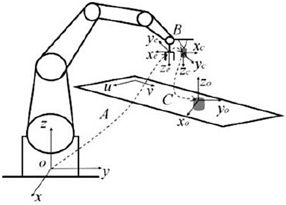
Coordinate frames for eye-in-hand robot system with monocular vision. A is the transformation matrix from the coordinate frame of robot base to the coordinate frame of end-effector, B is the transformation matrix from the coordinate frame of end-effector to the coordinate frame of camera, and C is the transformation matrix from the coordinate frame of camera to the coordinate frame of workpiece.

Implementation of step-by-step strategy in object positioning and grasping.
Vision-guided peg-in-hole assembly
After grasping peg and hole by each arm of the Baxter robot, we aimed to realize the peg-in-hole assembly task using the dual-arm robot. Normally, the peg-in-hole task can be realized if the relative position and orientation of the peg and the hole are known. However, it is difficult to obtain the relative position and orientation of the peg and the hole through vision due to the complex working environment. Instead of directly obtaining the relative position and orientation of the peg and the hole, we measured the relative position and orientation of the two end-effectors of the Baxter robot. The relative position and orientation between the object and the end-effector was predefined. Therefore, the relative position and orientation of the peg and the hole can be calculated by measuring the relative position and orientation of the two end-effectors for the Baxter robot. The PID controller was used to realize the position compensation. The process of vision-guided peg-in-hole assembly is shown in Figure 6.

Process of vision-guided peg-in-hole assembly.
The camera attached to the left arm is considered as an eye-in-hand system to obtain the relative position and orientation between the left end-effector and the right end-effector. To simplify the problem, we restrained the orientation between the end-effector and the workpiece to make the z-axis of the workpiece align with the z-axis of the end-effector. A chessboard was attached to the right end-effector to measure the position and orientation of the right end-effector, as shown in Figure 7. At this stage, the measurement of the position and orientation of the right end-effector can be considered as a Perspective-n-Point (PnP) problem. In this study, we utilized the Gauss-Newton-on-manifold method to solve the PnP problem. The details of Gauss-Newton-on-manifold method can be referred to in Lee and Moore. 24
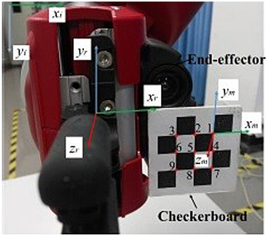
A chessboard attached on the right end-effector.
In the processing of peg-in-hole assembly, the hole was grasped by the left arm and the peg was grasped by the right arm. The configuration of left arm was fixed without movement of the end-effector. The position of the end-effector of right arm was derived based on the camera attached on the left arm. The relative position of the peg and the hole can be calculated using the derived vision information and coordinate transformation, which can guide the peg approaches to the hole to realize the assembly. The coordinate frame transformation is shown in Figure 8. The position error for the right end-effector between the desired position and measured position can be defined as follows

where

Coordinate frame transformation. B is the world coordinate frame, L is the coordinate frame of left end-effector, R is the coordinate frame of right end-effector, M is the coordinate frame of chessboard, and C is the coordinate frame of camera.
The coordinate transformation from the world coordinate frame to the coordinate frame of right end-effector can be defined as follows

Based on the coordinate frame transformation, the measured position of right end-effector under the world coordinate frame can be derived.
To compensate the position error of the right end-effector, we used the incremental PID control algorithm to adjust the motion of right arm. 25 The output derived by the incremental PID control algorithm is follows

where
After deriving the adjustment position for the right end-effector, the adjustment of joint angles for the right arm can be calculated based on equation (1).
Experiment
Grasping peg and hole based on monocular vision
In this experiment, the Baxter robot grasped the peg and the hole from the worktable by left arm and right arm, respectively, as shown in Figure 1. The camera attached on the robot arm was used to guide the robot arm position and grasp the peg or the hole. The outer diameter of peg is 39.8 mm, while the inner diameter of hole is 40.8 mm.
The process of grasping peg and hole is shown in Figure 9. The dual arm can quickly move to the upper of the peg and the hole and derive the position of peg and the hole based on the camera attached on the end-effector of each arm. After that, the robot arm moves the gripper approach to the peg and the hole. Due to the hardware of the Baxter robot, the gripper cannot move to the position of the peg and the hole exactly. As shown in Figure 9(c), the gripper first moved to the nearby of the peg and the hole. And then moved to grasp the peg and the hole with the slight adjustment, as shown in Figure 9(d). The peg and the hole can be grasped successfully by Baxter robot based on the step-by-step grasping strategy. To evaluate the proposed step-by-step grasping strategy, we made the robot arm move to the goal position from different initial positions. The result was shown in Figure 10. The robot arm moved to the nearby of the goal position and then moved to the goal position with slight adjustment.

Process of grasping peg and hole by Baxter robot.

Robot arm moves to goal position from different initial positions.
Peg-in-hole assembly based on vision-guidance
In this experiment, we used the Baxter robot to realize the peg-in-hole assembly task based on vision guidance. The size of peg and hole was the same as that described in last experiment. The posture of Baxter robot after joint initialization was shown in Figure 11. The initial joint configuration for left arm and right arm were set as (the unit for joint configuration is radian)

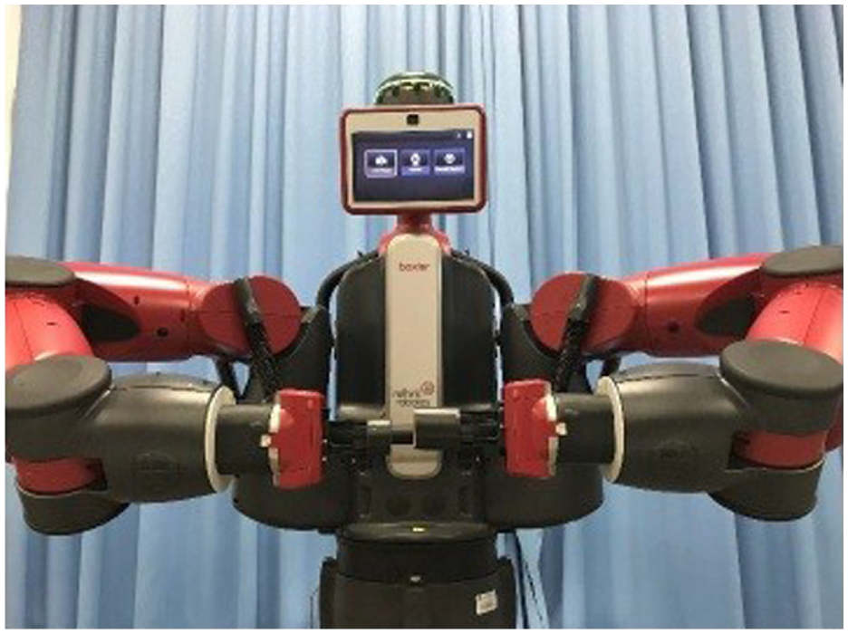
Initial posture of Baxter robot in peg-in-hole assembly.
The moving speed of right end-effector was set to 5 mm/s. The image processing time was 0.03 s. We used a laser tracking to measure the position of the right end-effector. The measurement accuracy of the laser tracker was 20 µm. The details of laser tracking can be found in Leica.
26
In the determination of PID parameters, we set

Positioning error of right end-effector under different
Without the vision guidance, the Baxter robot cannot complete the peg-in-hole assembly task with 1 mm clearance, as shown in Figure 13. This is because the Baxter robot has SEA in each joint, which results in low stiffness and unstability in positioning. With the vision guidance, the positioning error can be derived and be compensated. To check the stability of the vision guidance, we measured the positioning error for several times, as shown in Figure 14. From the results, we can find that the positioning error for the Baxter robot arm can be limited in 1 mm with vision guidance. Figure 15 shows an example of peg-in-hole assembly under the vision guidance. The Baxter robot can realize the peg-in-hole assembly successfully. The video for the process of peg-in-hole assembly can be found in the accompanying material. In the process of peg-in-hole assembly, the right end-effector of Baxter robot moves to the left end-effector in z-axis direction with a given constant speed. The movement of right end-effector in x, y direction is controlled based on PID controller to eliminate the positioning errors in x, y direction. Without force feedback, the motion of right end-effector cannot be adjusted in z direction when the peg contacts the hole.
Peg-in-hole assembly without vision guidance.

Positioning error under different tests.

Peg-in-hole assembly under vision guidance.
Conclusion
In this article, we proposed a vision-guidance method for a Baxter robot to realize the peg-in-hole assembly task. A step-by-step grasping strategy was proposed to position and grasp the peg and the hole. The positioning error was derived by the camera attached on the robot arm and was compensated through PID controller. The peg and hole on the worktable can be grasped and assembled by the Baxter robot in an experiment. The experimental results show that the vision-guidance method can make the Baxter robot realize the peg-in-hole assembly task with 1 mm clearance between the peg and the hole.
In future work, the orientation of peg and hole will be taken into account to complete the peg-in-hole assembly with different shapes of peg and hole.
Footnotes
Handling Editor: Chenguang Yang
Declaration of conflicting interests
The author(s) declared no potential conflicts of interest with respect to the research, authorship, and/or publication of this article.
Funding
The author(s) disclosed receipt of the following financial support for the research, authorship, and/or publication of this article: This work was supported by the Scientific and technological project of Guangzhou under grant 201707010318, Natural Science Foundation of China under grants U1501247 and 51505151, Research Project of State Key Laboratory of Mechanical System and Vibration under grant MSV201605, and Natural Science Foundation of Guangdong Province under grant 2015A030310239.