
Abstract
In this article, a novel, efficient grasp synthesis method is introduced that can be used for closed-loop robotic grasping. Using only a single monocular camera, the proposed approach can detect contour information from an image in real time and then determine the precise position of an object to be grasped by matching its contour with a given template. This approach is much lighter than the currently prevailing methods, especially vision-based deep-learning techniques, in that it requires no prior training. With the use of the state-of-the-art techniques of edge detection, superpixel segmentation, and shape matching, our visual servoing method does not rely on accurate camera calibration or position control and is able to adapt to dynamic environments. Experiments show that the approach provides high levels of compliance, performance, and robustness under diverse experiment environments.
Introduction
An aging population and rising labor costs are acute challenges facing society, resulting in a high demand for indoor service robots. Service robots working in indoor environments, such as homes or offices, often need to handle a variety of grasping tasks that require the ability to recognize the target object in a complex or dynamic background environment. 1,2 Due to uncertain factors, such as illumination, occlusion, and object posture, as well as the challenges of executing a real-time response by indoor service robots and choosing the proper gripping positions, it is difficult to design a lightweight recognition algorithm that can define different target objects whenever necessary.
Research on robotic grasping has resulted in many different grasping methods. 3 –6 Recently, deep-learning techniques have emerged as the most preferred methods among the approaches in the field of grasp synthesis. 7,8 These methods use various versions of convolutional neural networks (CNNs) to identify the objects to be grasped, 9,10 which means they demand a large amount of data as well as time for training and testing; the approaches also require an expensive hardware environment. However, the results of these methods often include problems with overfitting and lack reasonable generalization ability and the ability to be well-interpreted. Therefore, the methods based on deep-learning technology are difficult to apply to indoor robotic grasp tasks with variable target objects, viewing angles, and a dynamic environment.
In this article, a novel, fast, and lightweight method is proposed for robotic object recognition and grasping tasks. The method can extract the contour information of objects contained in an image using edge detection and superpixel segmentation techniques and calculate the similarity between the two contours with a shape descriptor technique to complete the object recognition. Then, using the relative distance between the object centroid and the gripper, the algorithm guides the robot to move the gripper to the object and form a proper grabbing posture to complete the grasping task.
When compared with the prevailing deep-learning methods, our approach has the following advantages. First, it can flexibly adapt to the variable positions and postures of the target objects and the changes in the environment because the recognition method is based on the shape information of the objects, which is a stable, long-lasting, and essential feature. Second, since the object is identified by shape features, this method does not require a large number of training samples, which means that it saves cumbersome manual labeling work and greatly lowers the requirements for a computing hardware. Third, this method combines the object recognition module with the robot control module to form a hand-eye coordination mechanism with feedback, that is, a closed-loop control process. This process means it is not necessary to calculate the exact absolute coordinate values, only the relative positional offset between the object and the gripper, which greatly simplifies the calculation of the conversion between multiple coordinate systems. This process also improves the robot’s adaptability to the environment and the response speed to the tasks. Fourth, this method is highly interpretable. The human visual system recognizes objects mainly based on the contour information, 11,12 which means our method utilizes the results of cognitive research.
Related work
Robotic grasping is a widely studied topic. Generally, these techniques can be grouped into two categories: empirical methods and analytic methods. Analytic methods 3,13 use mathematical and physical models of geometry, kinematics, and dynamics to calculate stable grasping strategies. However, such methods are not easily applied to real-world scenarios, since it is difficult to model the physical interaction between the gripper and the object. Empirical methods 14 –16 tend to avoid the computation of physical or mathematical models that mimic human grasping strategies. These techniques associate the appropriate grasp points with a database storing object model or shape information based on object type definitions.
Recently, techniques based on deep learning have become popular. 8,10,17 –19 The strategies are similar: A certain number of grasp candidates are extracted from the image or point cloud, and the algorithm ranks them with a CNN and considers the object of the highest score the one to be grasped. Once the object is identified, the robot performs an open-loop grasp, which requires the precise calibration between the camera and the gripper, as well as a completely static grasping environment. These methods require a large number of labeled samples for training and testing, which not only imposes high requirements on the hardware environment but also requires a lot of manpower and time. The models usually lack reasonable generalization ability. However, CNNs often contain millions of parameters and rank grasp candidates with a sliding window at discrete intervals of offset and rotation, which results in a long processing time that can be up to tens of seconds. Deep-learning methods often only achieve coarse positioning with bounding boxes, which is not enough for precise grasping tasks.
The approach proposed in this article identifies an object based on the shape information, can quickly complete the pixel-level recognition tasks, and does not require a pretraining process or expensive hardware environment. In addition, this method is highly adaptable to changes in the environment as well as the position and posture of the object because of the shape-based recognition algorithm. Instead of bounding boxes, the recognition result is the pixel-level outline of the object, which is more conducive to the following grasping tasks.
Shape-based object detection with background interference
Shape-based object representation method
In the early work of one of the authors, multiscale triangular centroid distance (MTCD) descriptors were proposed to represent shapes. 20,21,22 –25 MTCD descriptors can be adapted to translation, scale, rotation, and deformation. In addition, it is convenient and quick to calculate the difference between shapes represented by MTCD descriptors, so here we used this method to calculate the similarity between two contours.
Given a shape S, let sequence

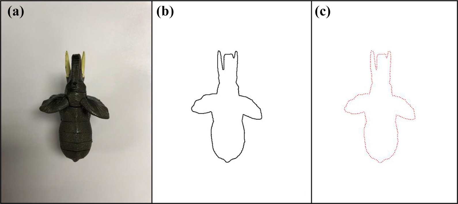
(a) The original image of an elephant model; (b) the contour shape of the model; and (c) the set of points obtained by equidistant sampling of the contour.
Given a certain point


Acquisition of centroid point
T triangles can be obtained for each sample point Pi
, where T represents the scale number, which is set to

Then, we can obtain a column vector vi

Thus, given a certain shape S, we can obtain an T×N matrix M

It is easy to prove that M has intrinsic invariance to translation of the contour of S from its definition. In addition, for each row of M, we normalize M by dividing the elements by the maximal absolute value of each of row as follows

Next, to obtain invariance to the starting point of our shape descriptor, Fourier transform is applied to each row of M and the phase information is discarded. For easy explanation, let rt denote each row of M. Then, the discrete Fourier transform for rt can be calculated as

It is not difficult to prove that

Here, we set

(a to c) The characteristics of line 1, line 80 and line 150 of shape descriptor

Structured random forest is used for edge detection. The left side shows the original image and the right side shows the edge detection result.
Given two shapes S
1 and S
2, whose shape descriptors are

The smaller the dissimilarity
Elimination of redundant information in images
To obtain the line information in the image, we referred to Dollár and Zitnick’s work 26 on edge detection and the work of Radhakrishna et al. 27 on superpixel segmentation. In one study, 26 the use of the structured forest technique for edge detection achieved good results.
However, since real images often contain a lot of noise, the results of edge detection involve much redundant information for object recognition tasks. On the other hand, superpixel segmentation, which groups pixels into perceptually meaningful atomic regions, can effectively eliminate the effects of noise in the image.
The superpixel segmentation algorithm we apply is easy to understand, and it requires only one parameter provided by users, that is, k, which is the desired number of the superpixels.
Given a color image in Commission Internationale de l'Eclairage Lab (CIELAB) color space, the algorithm firstly divides the N pixels into a regular grid, whose interval is
Next, we traverse all the centers and associate each pixel with the nearest cluster center whose search region overlaps its position. The algorithm searches a limited region, the size of which is set to

Then, we normalize the spatial proximity and the color proximity by their respective maximum distances within a cluster, that is, NS and NC , to combine dc and ds into a single measure of distances between a pixel and a cluster center. Let D denote this measure, whose definition is as follows

where
The cluster centers are then adjusted to the mean vector
Finally, we traverse all the pixels and assign the disjoint pixels to their closest superpixels to enforce connectivity. The segmentation result is shown in Figure 5.

The left side shows the original image and the right side shows the result of superpixel segmentation.
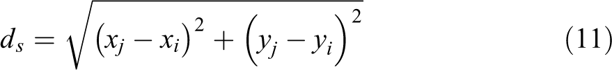
However, superpixel segmentation also results in a considerable amount of edge information for the superpixel blocks, which is also redundant information for object recognition. The approach proposed in this article combines the results of edge detection, shown in Figure 4, and superpixel segmentation to extract the true contour information of the objects contained in the image.
Figure 6 shows this algorithm in action. Assume that the input image is I, of which the size is
(a) The original image; (b) the result of superpixel segmentation; (c) the result of edge detection; and (d) the result of combination of (b) and (c).
Next, we refine the contour lines in IC , that is, reduce the width of lines to one pixel and then take the branch points, whose number of adjacent points is more than two pixels, as the line end points to extract the contour line information C, which is a set of lines, where a line is a set of coordinate values of pixels.
Extraction of contour template
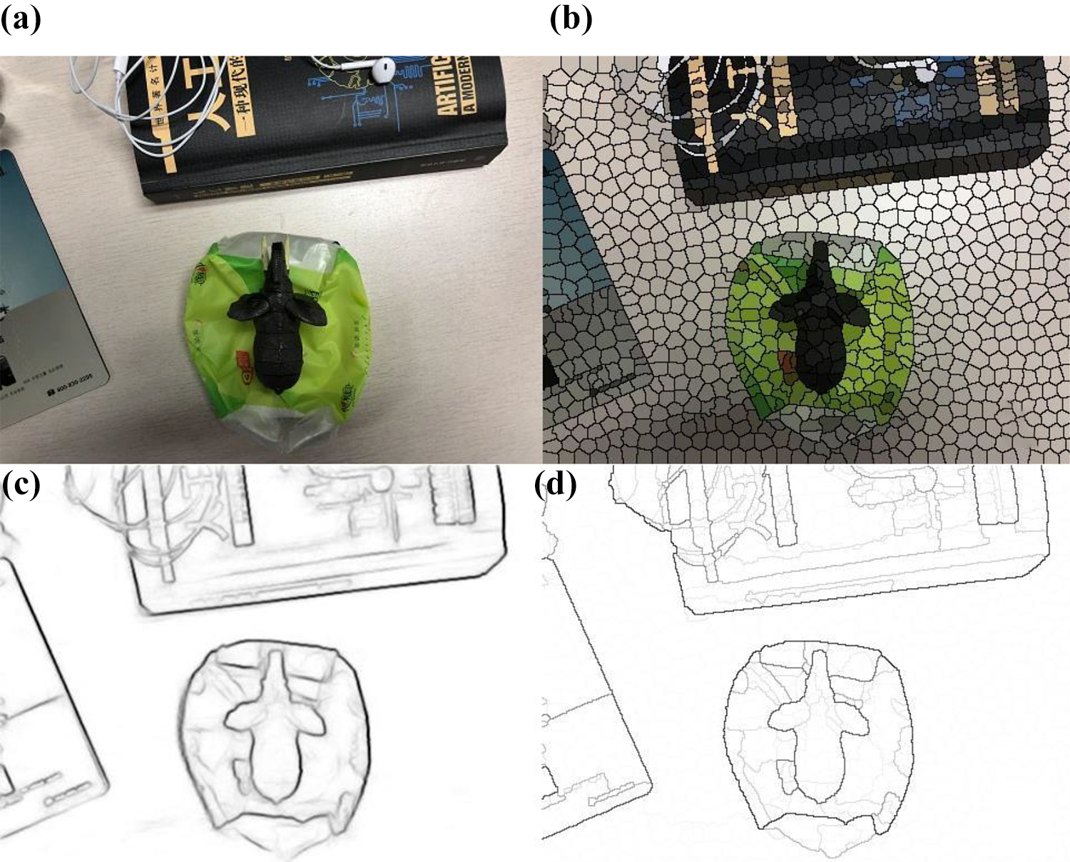
To obtain the shape contour of a given object, we photograph the object with a relatively monotonous background and remove redundant information of the image captured using the method above. As is shown in Figure 8, the image of animal models with a white background captured by a camera is processed by edge detection and superpixel segmentation, respectively. Then, the remaining pixels are filtered, and the lines are refined so that the shape contour of the models is obtained. The shape contour of a given object obtained above can be used as contour template in the following process, as shown in Figure 7.

Line set
Animal models in a relatively monotonous background are photographed, and the images captured are processed with edge detection and superpixel segmentation, and then the remaining pixels are filtered and lines are refined. The left side of each row shows the original images and the right side of each row shows the obtained contour templates.
Line segments combination based on heuristic search
Heuristic search, also known as informed search, reduces the search scope and complexity of the problem to be solved by referring to the heuristic information. The objective of heuristic search is to produce a solution in a reasonable time frame that is good enough for solving the problem. Heuristic search can avoid combinatorial explosions by guiding search to the most promising direction using heuristic information. The stronger the heuristic information, the less the search branches. The function used to evaluate the importance of search nodes is called valuation function, which is generally in the form of:

where
Given an image, after the preprocessing described above of eliminating the redundant information, we can turn the image to a set of line segments which includes the contour information. If we traverse all the combinations of the line segments in the set, then the combination of line segments that is most similar to the shape contour of a given object can always be found, which is obviously very time-consuming. By using the shape descriptor and shape dissimilarity we introduced above, we can guide the search path to avoid unnecessary search nodes and thus greatly improving search efficiency.
Given the contour template M of the object to be grasped, M is a binary map where pixels have a value of 1, indicating they belong to contours. As shown in Figure 9, the algorithm looks for a seed line Cs
in C as the starting state for the following search, using the heuristic search strategy. Cs
should have a certain length because the short lines correspond to very few sampling points, which result in finding too many similar parts on the template. Cs
should also have a certain degree of curvature, since a real scene in images always involves a lot of line segments that tend to be mismatched with the line segment of the template. With these restrictions, the search domain for Cs
is greatly reduced, and Cs
, which indicates the line most similar to some part of the object to be grasped, is searched exhaustively in the remaining line set

The process of matching an object to be grasped is shown in order from left to right and from top to bottom. (a) Search for the seed line. (b) to (e) Process of each iteration of the search. The candidates are marked in white, and the most similar line is marked in yellow. (f) Matching result.
After Cs
is found, the following searches only consider the line set

The first row of each column shows the contour template; the second row of each column shows the original image captured by the camera; the third row of each column shows the line segments extracted from the image; the fourth row of each column shows the seed line found by the algorithm; and the fifth row of each column shows the final recognition result.
Finally, the centroid P of Cs
is calculated to guide the robot to execute the grasping task. Suppose Cs
=
Determination of the grasp position with contour detection
After the recognition task is completed, the shape contour

Since the gripper is open to a certain extent, an appropriate gripping position is needed to guide the robot to rotate the sixth joint to form a proper grip posture to execute the grasp task. We took into consideration the general size of the gripper mounted on the robotic arms and the irregularity of the shape of the object to be grasped. The proposed approach uses the relatively narrow concave portion of the object outline as the grasping position so that it can handle different situations, such as when the gripper is too small to grasp a relatively large object and make the grasping state as strong as possible.
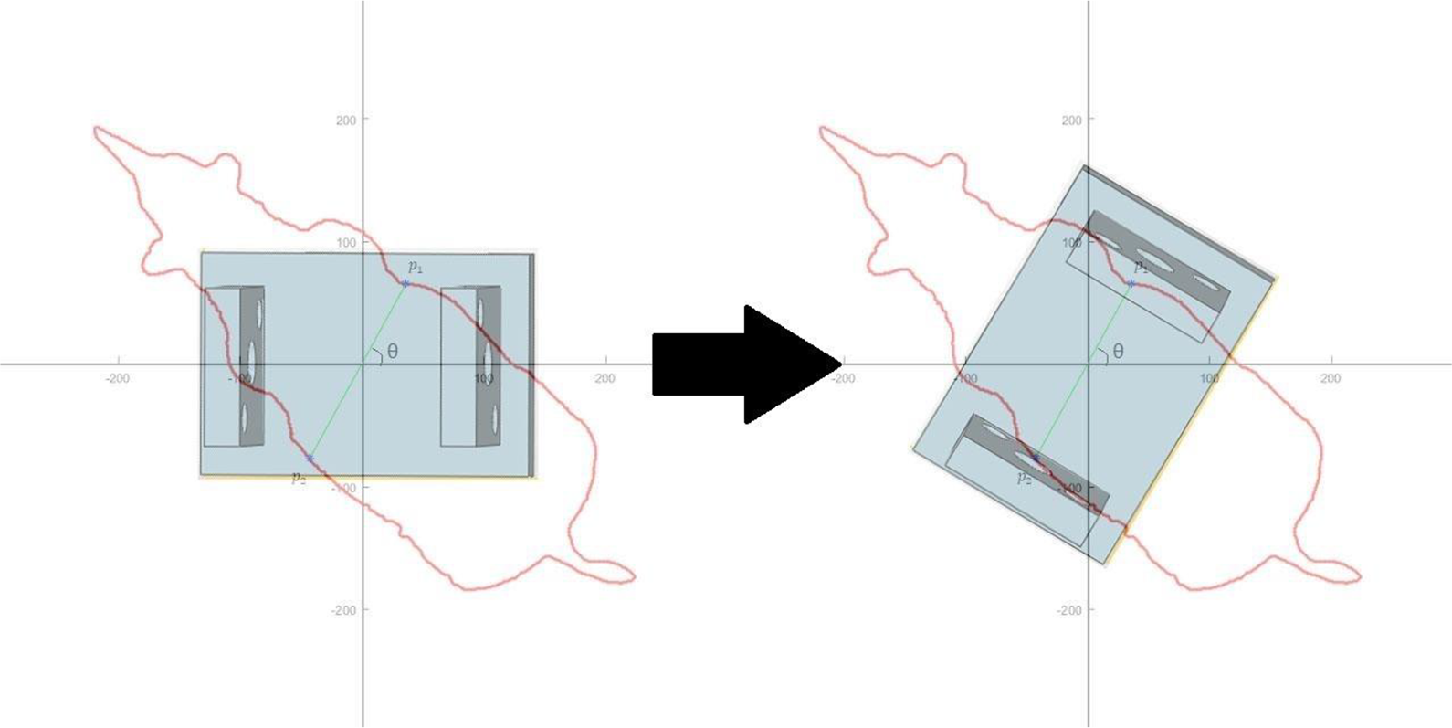
The result of the recognition method discussed in this article, a precise outline of the contour of the object, indicates that the gripping position that meets the requirements above can be obtained in a simple way. First, make a straight line l passing through the centroid C of the object outline and measure the width of the contour using the Euclidean distance d between the intersections p 1 and p 2 of l and contour Cs . Rotate l at a certain angle interval θ, and obtain sets of intersection points and corresponding distance values. After a rotation of 180°, the set of intersection points with the smallest distance value is taken as the final grasping position.
As shown in Figure 11, the normal line between the two clips of the gripper is initially collinear with the horizontal axis. After the appropriate grasping position is calculated, it is only necessary to control the gripper to rotate θ degrees counterclockwise to form the optimal grasping posture.
The straight line
Guiding the robot to approach the object to be grasped using the recognition results
Interaction between the recognition module and the robot control module
As is shown in Figure 12, the computer is connected with the control cabinet of the robotic arm through a twisted pair. The world coordinates (the origin is in the center of the base of the robotic arm) the gripper to be moved to are transferred to operating system of the robotic arm using transmission control protocol protocol. The coordinate data are then transformed to the rotation angles of each of the six joints.

(a) Control cabinet in the blue wireframe and robotic arm in the red wireframe; the computer running the program transmits data through a twisted pair to control cabinet using TCP protocol. (b) The establishment of coordinate system using the base center of the robotic arm as the origin. TCP: transmission control protocol.
As shown in Figure 13, the images captured by the camera are transmitted to the computer; the latter takes the images and the appropriate template image as parameters and invokes the recognition module to execute the recognition tasks. Next, the relative position of the object centroid to the center of the camera is calculated. If the centroid is in the central area of the camera field of view, the control module moves the gripper down to grasp the object. Otherwise, it moves the gripper to the centroid position of the object according to the relative position and makes the camera capture an image.

Interaction between the recognition module and the robot control module.
Object recognition flowchart
The flowchart in Figure 14 corresponds to Algorithms 1 and 2.
Contour segments generation.


Search and combine contour segments


Sketch map of the object recognition module.
Robot control module flow chart
As shown in Figure 15, the robot control module accesses the memory location storing the object recognition result at a certain frequency and reads out if it is updated, where the recognition result refers to the relative position of the object centroid to the center of the camera field of view. If the centroid is in the center, control the gripper to move down for grasping, otherwise move it closer to the centroid of the object to be grasped.

Sketch map of the robot control module.
Experiments
Our environment
Figure 16 shows our experiment environment, which consists of a computer connected to the robot control cabinet, an SD700E industrial robot arm (yellow) with six degrees of freedom, ±0.03 mm repeatability, and 700 mm radius. An EFG20 electric gripper (silver white) was mounted on the end flange of the arm, above which a simple camera (Logitech C310) was mounted. The total cost of the hardware set was less than US$15,000.

Our experiment hardware set.
The surface of the workbench was set up to be complicated and messy on purpose. The state of the table was changed during the experiments, such as when we disturbed the relative order of the objects and changed their postures and positions, to highlight the robustness of our approach.
Experiment result
Figures 17 to 19 show the application of our method in the real environment. Each row in Figure 18 shows the relative positions between the gripper and the object to be grasped, that is, rhino model, before and after the recognition process was done. To present the robustness of our method, each time when the gripper was moved above the object referring to the recognition result, the object was moved to a different position with a different posture as well as the surrounding objects, which resulted in another round of recognition process. Once the state of the object was not changed after the gripper was moved above it, the gripper would be moved down to execute the grasp, as is shown in the last row.
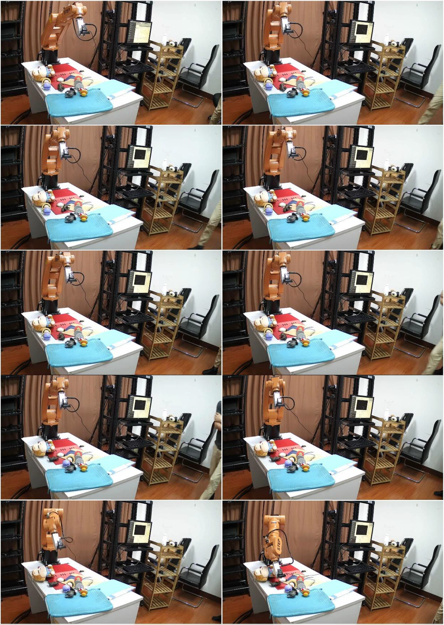
The left side of each row shows the initial position of the gripper and the object to be grasped, that is, rhino model; the right side shows the position the gripper was moved to once the object was recognized. As the first four rows show, the object was moved to different positions and placed in different postures once the gripper was moved above it, and the state of the surrounding objects was also changed (as is shown in third row). The last row shows that when we did not change the state of the table after the gripper was moved above the object, the gripper was then moved down to execute the grasp task.

The left side of each row shows the captured image; the middle shows the contour information extracted from the image; and the right side shows the recognition result. The two ends of the red line point to the centers of the object to be grasped and the camera mounted on the gripper, respectively.

Once the precise shape contour of the object to be grasped is obtained, the appropriate grasping points are calculated to guide the robotic arm to execute the grasp task. (a) The initial state of the robotic arm; (b) the gripper was moved above the object according to the recognition result; (c) the gripper was moved down to the object; and (d) the gripper was rotated to form an appropriate grasp posture according to the grasp points. It is difficult to form such a posture if there is no such a pixel-level shape contour.
Figure 18 shows the details of recognition process corresponding to different positions of the gripper displayed in Figure 17. From left to right on each row, the image captured by camera mounted on the gripper, the line segments representing the contour information extracted from the image and the recognition result are displayed respectively. The red line in the right side of each row connecting the centers of the camera view and the object to be grasped shows the relative position between the gripper and the object, which can be used to guide the robotic arm to move the gripper above the object.
After the precise contour of the object to be grasped is obtained, the appropriate grasp point can be calculated in a simple way to guide the robot to perform grasp tasks, as is shown in Figure 19.
We are unable to include enough pictures to show the entire recognition and grasp process owing to space constraints. However, a video clip is provided to show the whole experiment process.
Discussion
Although the object recognition methods based on deep learning are outstanding for classification tasks, they can only generate bounding boxes containing the object to be grasped when guiding a robot to perform grasp tasks. In addition, deep-learning methods require a lot of training and test data and computing time as well as an extremely extensive hardware environment. Therefore, these techniques are not suitable for robot grasp tasks, especially those that should be defined temporarily.
The object recognition module required for robot grasp tasks should be sufficiently lightweight and fast, while still being able to handle the noisy environment because the environment affects the motion planning of the robot. The recognition proposed in this article starts with the shape of the object and extracts the contour information from the original image which is stored in the form of lines. In addition, the heuristic search strategy greatly reduces the search domain so that the object can be effectively identified from the chaotic environment, which makes our method fast and robust enough to be more suitable for various robot applications.
Footnotes
Declaration of conflicting interests
The author(s) declared no potential conflicts of interest with respect to the research, authorship, and/or publication of this article.
Funding
The author(s) disclosed receipt of the following financial support for the research, authorship, and/or publication of this article: This work was supported by NSFC under Project 61771146 and Project 61375122.
Supplemental material
Supplemental material for this article is available online.
References
Supplementary Material
Please find the following supplemental material available below.
For Open Access articles published under a Creative Commons License, all supplemental material carries the same license as the article it is associated with.
For non-Open Access articles published, all supplemental material carries a non-exclusive license, and permission requests for re-use of supplemental material or any part of supplemental material shall be sent directly to the copyright owner as specified in the copyright notice associated with the article.