
Abstract
Cost- and time-effective automated assembly of micro-sized objects within small tolerances is still a challenge to the present-day manufacturing industry. In this article, the details of the development of a low-cost, two-dimensional system capable of rapid micro-assembly are presented. The use of a basic webcamera without any external optics makes the system light and compact. In addition, an innovative thresholding technique for binarization and a novel algorithm for fast autofocusing with defocused images have also been discussed. Peg-in-hole insertion tasks using micro-objects of 100 μm have been successfully demonstrated using the system. The system has an accuracy of about 20 μm along the X- and Y-axes and a repeatability of less than 4 μm in performing peg-in-hole tasks.
Introduction
With development in engineering technology, micro-sized parts such as miniature gears, pumps, sensors, actuators, and so on are easily manufactured. The impending requirement for more complex functional devices coupled with the limitations of the current micro-machining techniques calls for the development of rapid micro-assembly systems in building such devices.
Machine vision techniques offer advantages of noncontact sensing, part identification and easy position control and thus have been the main choice for automated assembly. Although pick-and-place tasks have been accomplished in the macro-domain since a long time, the first such system for performing micro-domain tasks was developed in late 1990s by Ralis et al. 1 Their system comprising of multiple sensors demonstrated a relative part placement with a precision of 17.9 μm in X-direction and 26.8 μm in Y-direction, with a repeatability of 2 μm in X- and Y-directions. Since then, researchers have worked extensively on visual-based micro-positioning 2 and developed numerous micro-assembly stations3,4 for a variety of applications. Similarly, studies have focused on algorithms for improving assembly and tracking performance. 5 A state-of-the-art review on the assembly and manipulation of micro-devices is presented in Cecil et al. 6 and Jain et al. 7
All the discussed systems involved the use of a microscope or multiple camera arrays as vision sensors, which make them very costly and unnecessarily bulky. However, it is observed that the majority of the micro-assembly tasks 8 deal with the objects of size 100 μm or more, with positional accuracies of the order of a few micrometers. However, it is envisaged that this level of output can be achieved even with a simple and cost-effective sensor like the webcamera. It is the focus of this article, which includes development of visual algorithms and hardware setup and experimentation to evaluate capability of the system.
Vision algorithms
The features of interest (FOI) in a typical micro-assembly operation are usually holes of different sizes and shapes on the workpiece, which appear dark against the metallic surrounding (light gray). In these situations, colored images, while being computationally more expensive than grayscale images, offer no additional advantages and hence grayscale images are used in this work. As compared to microscopes or typically used camera systems, the images obtained from a webcamera are of low resolution (320 × 240 to 1280 × 840), which is a severe limitation for resolving micro-sized FOI. Therefore, in order to improve the effective image resolution, the camera working distance was kept very small (thus increasing the zoom), close to the focus limit resulting in low-contrast images. To address this issue, specific visual algorithms have been developed and details of which are discussed below.
Thresholding
Thresholding 9 is the most critical step in any image processing operation. A stringent threshold may result in partial/complete distortion of the required object, while relaxation may lead to unwanted detections.
Due to the low contrast of the captured images, clustering-based thresholding techniques like the one described by Otsu 10 gave poor results (see Figure 1). In fact, when the Otsu threshold was applied, a significant number of FOI pixels (which gradually merged into the surrounding) were lost and a very small binary image of the FOI was formed as shown in Figure 1. To overcome this problem, a histogram-based threshold (T), which takes into account the intensity variation across the image, is proposed in equation (1) as given below
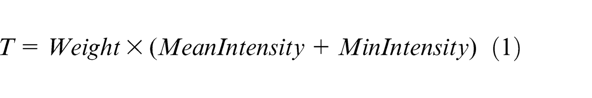
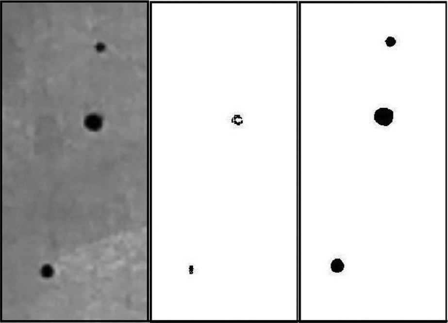
Grayscale image of micro-holes 100, 200 and 400 μm in diameter (left), binarized image after Otsu thresholding (middle) and binary image using the proposed threshold with Weight = 0.85 (right).
In the above equation, MeanIntensity refers to the average image intensity (surrounding intensity), MinIntensity refers to the minimum intensity recorded (FOI intensity) and Weight is a constant between 0 and 1 but usually between 0.8 and 0.9. Given the uniform background and the fact that the FOI pixels form a negligible portion (0.4%−2%) of the image, it can be safely assumed that the non-FOI pixel values follow a Gaussian distribution around the average image intensity. Thus, incorporating the 3-sigma limits, 11 Weight is defined by equation (2) as given below
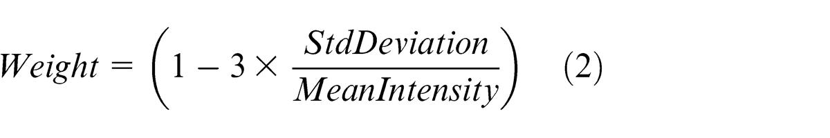
StdDeviation refers to the standard deviation of the pixel values. Figure 1 (right) clearly depicts the success of the proposed method, showing clean circular blobs of the holes, as almost 99.7% (theoretically) of the surrounding pixels are eliminated.
Autofocus
Autofocusing, essential to capture good contrast images, is achieved in commercial cameras by manipulating the lens parameters. This method is not suitable for positioning operations (especially with camera movement) as the vision system has to be re-calibrated every time the parameters change. However, it is known that at the best position (focused), the FOI area in binary image is minimum and the FOI average intensity (in grayscale image) is also minimum. Thus, the image is the darkest under this condition. Therefore, a quantity called AutoFocusParameter is defined in equation (3) to measure the extent of focus

where n is a real positive constant greater than 1. Thresholding as defined above is computed from the camera images at several points along the camera axis. The AutoFocusParameter (n = 2) values when plotted against different Z-positions along the camera axis produced a distinct peak (Figure 2) corresponding to the best focused value.
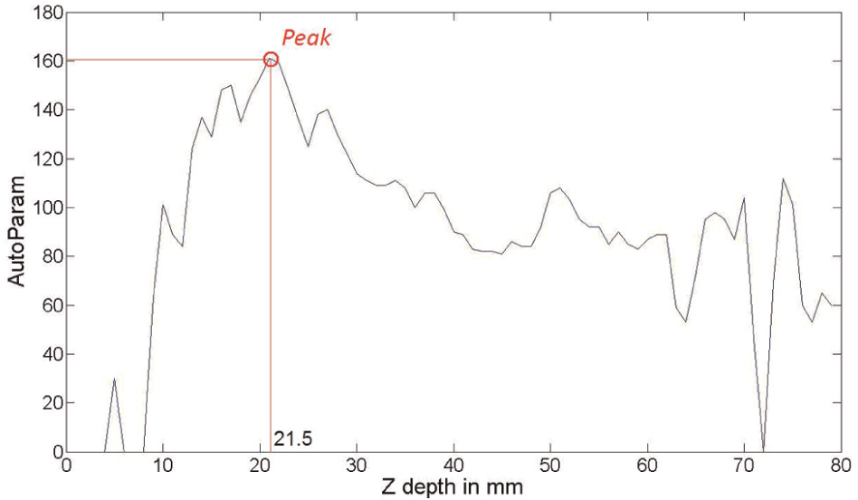
Plot of the autofocusing parameter with camera distance.
Thus, a novel algorithm is proposed, where the camera is moved (while keeping its properties fixed) gradually along its axis, between set end points, and the value for the AutoFocusParameter is computed at each position. The position with maximum value for the above parameter is assigned to be the best focus value. This method works specifically in situations where the FOI grows darker (lower intensity) with focusing. A typical printed circuit board (PCB) plate with holes of different shapes and sizes fits well into the above constraints.
Micro-object detection
A popular geometric approach, using Hu Moments, 12 is employed here to identify an FOI uniquely. The following four centralized moment equations (4)–(7), invariant under translation, rotation and changes in scale, are used
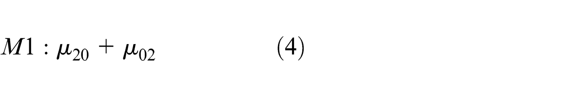
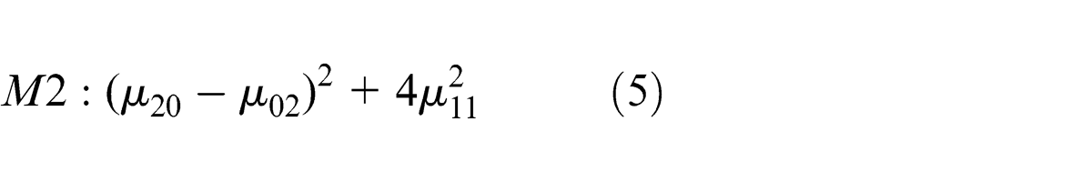
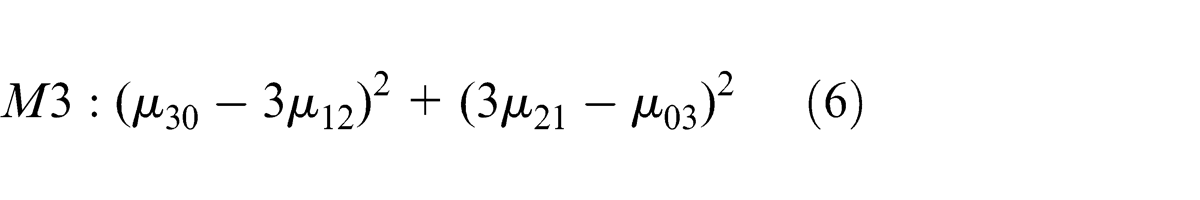
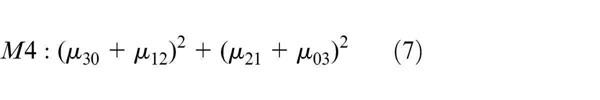
where
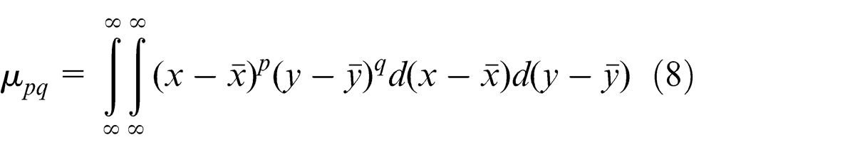
For each FOI in the image, a feature vector is generated with the four moment values, which are compared with reference feature vectors (of known FOI from database), and the one with the minimum Euclidean distance is assigned a match for that particular FOI.
Two-dimensional positioning
A proportional–integral–derivative (PID) control loop with a webcamera as feedback sensors is used for accurate stage positioning (approach similar to Wang et al. 5 ). First, the current position, Xcurr, of the FOI is determined using the camera image. Given the target position, Xtar, the calculated difference in motion is communicated to the motion controller. Appropriate values of the proportional (Kp), integral (Ki) and differential (Kd) gains are assigned; the required motion is computed using equation (9) below. The slides are then signaled to move accordingly
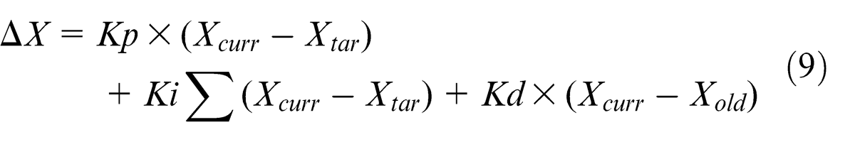
where ΔX is the new movement and Xold is the previous position of the FOI. This procedure is repeated till the required accuracy (ΔX) is reached.
Micro-assembly system
The hardware of the proposed micro-assembly system ccomprises of an imaging subsystem and a positioning subsystem. The imaging subsystem is represented by a complementary metal–oxide semiconductor (CMOS) webcamera (Logitech Quickcam Pro 9000), used as a position feedback sensor. The use of the webcamera not only makes the proposed system cost-effective but also light and compact. The positioning subsystem includes three high-performance linear stages (Newport ILS100CC). The direct current (DC) motor–actuated stages are mounted on a backlash free ball screw mechanism to ensure precise motion for accurate positioning. All processing operations are done using MATLAB on a Desktop PC (2.18 GHz Intel Dual Core CPU with a RAM), which serves the dual purpose of acquiring data from the webcamera, via the USB port, in addition to issuing the commands to the stages via the motion controller connected on the serial port. Figure 3 shows a schematic of the setup for two-dimensional (2D) assembly and machining.
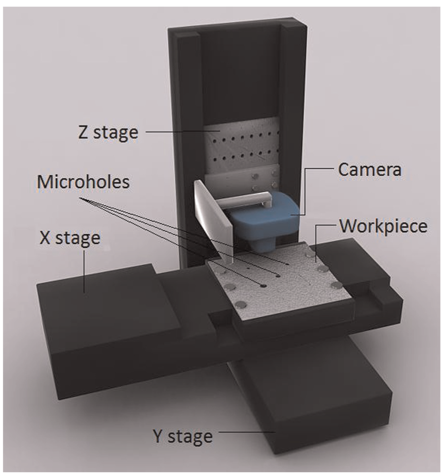
Setup for micro-assembly.
In the setup, two slides were mounted perpendicular to each other, one on top of the other and on a rectangular base. These slides provided motions in X- and Y-directions. The third slide was mounted perpendicular to the plane of both these slides (along the Z-direction) on the base. The workpiece, usually a micro-drilled plate, is mounted on the X–Y slide system as depicted in Figure 3. The webcamera along with the tool (drill or micro-gripper) was mounted on the Z-axis. The whole system was used in conjunction with the force-controlled micro-gripper 13 that was developed for manipulating micro-sized objects between 100 μm and 1 mm.
Experiments and results
It may be noted that in all the experiments described in this article, grayscale images of size 960 × 240 were captured using the camera at a steady rate of 30 frames per second (fps), unless mentioned otherwise. Also, to obtain the best FOI characteristics, the camera zoom was set to maximum and the working distance is maintained at the corresponding best focus height of about 37 mm.
Figure 4 shows a straight line plot of the real position coordinates against the pixel coordinates, with a slope (19.62-axis and 19.19-axis) of approximately 20 μm on each axis (repeatable to 0.2 pixels).
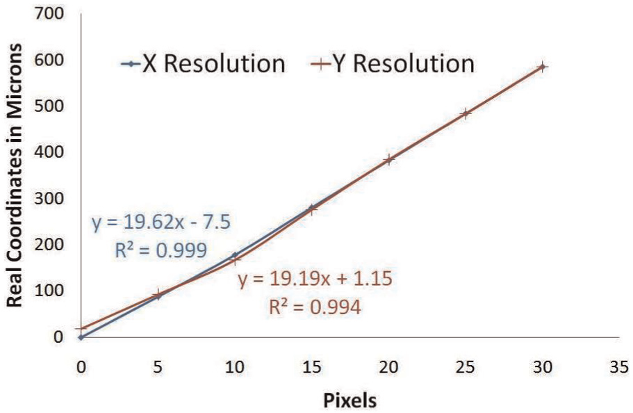
Resolution along the X- and Y-axes.
The developed autofocus algorithm yields good results, with the predicted camera heights for best focus differing from those obtained by the camera software only by maximum of 1.5 mm, that is, the maximum error of 4%. However, these small errors result in defocused images and thus need to be compensated for using the proposed threshold.
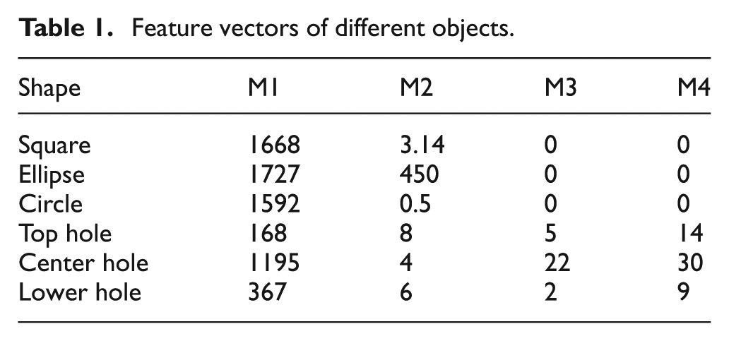
Micro-object recognition experiments were carried out with two different sets of objects: (1) of similar size but of different shape (a square, ellipse and circle, approximately 1 mm in size) and (2) of same shape but of different size (micro-holes of sizes 100, 200 and 400 μm) as shown in Figure 1. Table 1 shows distinct feature vectors (scaled up) for the above micro-objects proving the effectiveness of the moment-based object recognition algorithm. Furthermore, the M1 values (representing the total object area) are close for the square, elliptical and circular shapes proving that their areas are similar. On the other hand, for the holes, they are considerably different owing to their different sizes, thereby allowing easy classification. Each identification operation takes approximately 36.8 ms. This shows that the proposed system is ideal for real-time operation.
Feature vectors of different objects.
Micro-objects have been localized in real time within 20 μm of their target position (routine taking 45.6 ms on an average per iteration). Figure 5 plots the path of the central hole in Figure 1 as it was positioned from pixel coordinates (100, 350) to (400, 100).
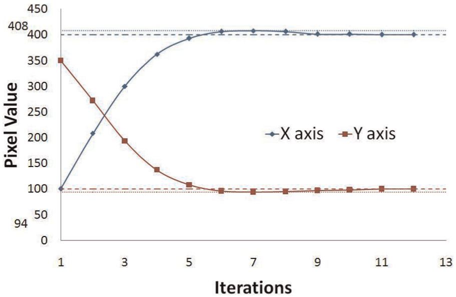
Localization response curve along the X- and Y-axes.
However, slightly under-damped characteristics are obtained. It is further noted that the maximum overshoot is minimal (6–8 pixels) and the settling time is good (about 10 iterations). Also, it was evident that there is no offset value at the end of the settling time, thus allowing precise positioning.
To demonstrate the capability of the system, peg-in-hole 5 insertion task (Figure 6) was successfully accomplished, where a cylindrical needle of 100 μm was inserted into three different holes of diameter 100, 200 and 400 μm in succession in a user-defined sequence (100-400-200-100) with the whole operation taking about 1.5–2 s per hole. The trajectory of the 200 μm hole is shown in Figure 7.
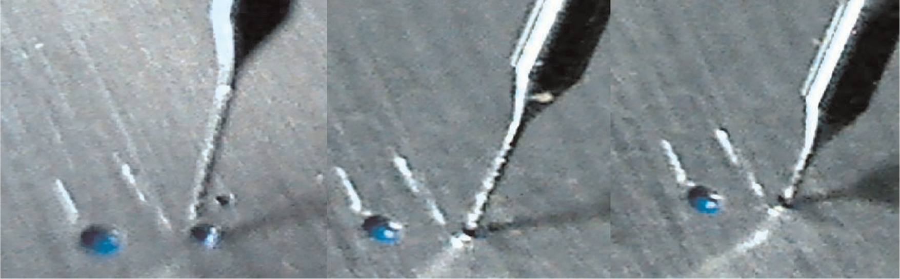
Sequence of images showing the insertion of the 100-μm needle into 200-μm hole.
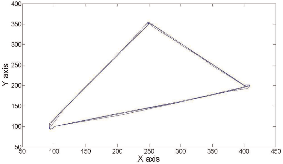
Trajectory of the selected hole during the hole-insertion operation.
It is observed that each cycle traces its previous path closely to within 2–3 pixels. The deviations observed at the vertices are due to the overshoot, which eventually reach zero about the target position during the settling period.
Conclusion and future scope
The objects of size 200 μm and above were easily characterized using the lowest resolution (320 × 240) images. Therefore, at least in such assembly systems, a simple webcamera can easily substitute the complicated microscope systems, thereby making it a low-cost system. With an accuracy of 20 μm along the axes and 4 μm repeatability, the system has demonstrated real-time micro-assembly of 100-μm-size micro-objects. In the future, the autofocusing algorithm will be exploited for Z-axis positioning, thus imparting it three-dimensional (3D) capability. Furthermore, the addition of a visual force feedback into the current setup will not only provide better control but also enable the system to handle delicate micro-objects. Such a system could perform complicated assembly operations and also find potential applications in the field of computer-assisted surgeries.
Footnotes
Declaration of conflicting interests
The authors declare that there is no conflict of interest.
Funding
This research received no specific grant from any funding agency in the public, commercial, or not-for-profit sectors.