
Abstract
The finite element method is employed to calculate the transmission loss of three-pass perforated reactive and hybrid mufflers. The effects of perforated tubes and bulkheads on the transmission loss of three-pass reactive mufflers are investigated numerically. Two types of hybrid mufflers are considered, and the effects of sound-absorbing material filling and packed outlet tube on the acoustic attenuation performance of mufflers are analyzed. The perforations of the tubes and bulkheads and sound-absorbing material filling are demonstrated to have significant influence on the acoustic attenuation behaviors of the mufflers. The perforation of the tubes and bulkheads may shift the resonance from the low- to middle-frequency range. The sound-absorbing material filling in the middle chamber improves the acoustic attenuation performance at middle to higher frequencies and provides a relatively flat and broadband acoustic attenuation. It is found that the solid inlet or outlet tube replacing the perforated tube and sound-absorbing material filling in the middle chamber increases the pressure drops, while the rest configurations change the pressure drops slightly.
Keywords
Introduction
Three-pass perforated (TPP) muffler is a highly desirable device to reduce the vehicle’s exhaust noise with reasonable low backpressure. Dickey et al. 1 developed a one-dimensional (1D) time-domain approach to predict the acoustic attenuation performance of the typical TPP muffler. Munjal2,3 and Selamet et al. 4 then proposed the corresponding 1D frequency-domain computational approaches to determine the acoustic attenuation performance of the TPP mufflers. The 1D approaches are valid only at low frequencies since these studies assumed the plane wave propagation in the axial direction and excluded the effect of three-dimensional (3D) waves inside the mufflers. The numerical methods such as finite element method (FEM) and boundary element method (BEM) are no longer confined to a plane wave treatment. Ross 5 introduced the FEM to determine the transmission loss of simple perforated muffler using the measured acoustic impedance of perforation. His predictions showed good agreement with the measurements at low frequencies. Ji and Selamet 6 applied the substructure BEM to predict the acoustic attenuation performance of TPP mufflers. The effects of length and porosity of perforation, lengths of the expansion chamber and the end cavities, as well as duct extensions into the end cavities on the acoustic attenuation performance of TPP mufflers were investigated in detail. Ji and Fang 7 employed the 1D plane wave theory and 3D FEM to predict the transmission loss of the TPP mufflers with end resonator. Their study showed that the end resonator may improve the acoustic attenuation performance of the TPP muffler at low frequencies. Munjal and Krishna 8 applied transfer matrix method to predict the transmission loss of the three-pass double reversal muffler which consists of three perforated tubes and presented a flow-resistance network approach to evaluate the mean flow distribution. Verma and Munjal 9 investigated the effects of the absorptive material, porosity of the baffle plates, porosity of the perforated tubes, as well as the length of perforation of the perforated tubes on the acoustic attenuation performance of a three-chamber U-bend hybrid muffler by 1D transfer matrix method and 3D FEM.
However, to the knowledge of the authors, the study on the TPP mufflers with perforations on the inlet and outlet tubes within the end cavities and the bulkheads, as well as the sound-absorbing material filling, has not been published, which is widely used in the practical engineering. The objective of this study is then to investigate the effects of the perforations on the tubes and bulkheads as well as the sound-absorbing material filling on the acoustic attenuation performance of TPP mufflers using the 3D FEM. The study may provide the guidelines for TPP muffler designs.
Following the introduction, section “FEM and experimental validation” describes the FEM and experimental validation briefly, section “Results and discussions” exhibits the influence of perforation and sound-absorbing material filling on the acoustic attenuation performance and flow resistance, and section “Conclusion” concludes the study with final remarks.
FEM and experimental validation
FEM
The sound pressure inside the muffler is controlled by the Helmholtz equation 10

The equation can be solved numerically by the FEM. With Galerkin’s method of weighted residuals, the finite element (FE) equation is expressed as follows

where
For the TPP mufflers in this study, there are four boundary conditions (BCs) as follows:
The rigid wall

The inlet with normal particle velocity

The outlet with impedance

The perforated surface.
The sound pressure difference and the normal particle velocity


where

where
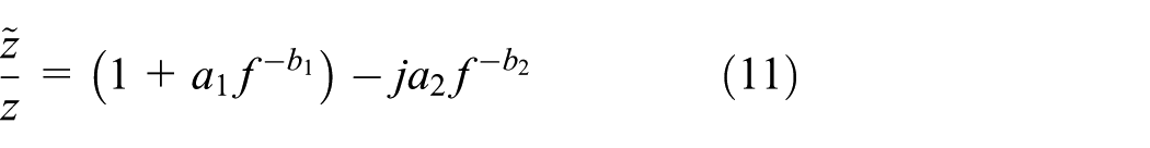
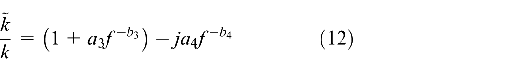
When one side of the perforation is attached by the sound-absorbing material, the acoustic impedance of perforation is modified as follows 12
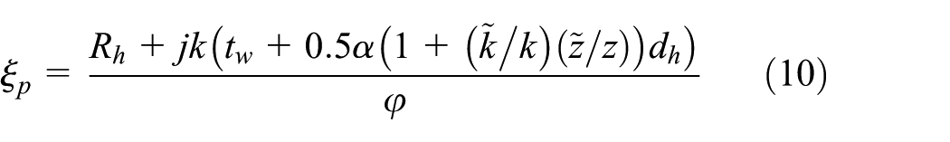
The sound-absorbing material can be described as the equivalent fluid with complex impedance
In this study, the fiberglass used by Lee and Selamet
14
is selected as the absorbing material. The average diameter of the fibers
Transmission loss
The transmission loss is used to evaluate the acoustic attenuation performance of TPP mufflers. It can be calculated by the following equation in the frequency range below the plane wave cut-off frequencies of the inlet and outlet tubes
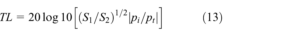
where S1 and S2 are the cross-sectional areas of the inlet and outlet tubes, respectively, pi is the incident sound pressure in the inlet tube, and pt is the transmitted sound pressure in the outlet tube.
Validation
The FEM software COMSOL Multiphysics is employed to calculate the transmission loss of mufflers. The measurement of transmission loss may be found in the work by Tao and Seybert. 15
In order to verify the accuracy of FEM, the typical TPP muffler shown in Figure 1 is chosen to compare the transmission loss predictions with measurements. The muffler has the inner diameter of

Three-pass perforated tube muffler with circular cross section.
The muffler shell is set as the transparent vision to view the internal structure of the muffler shown in Figure 2. The blue and red regions represent the perforated and solid tubes, respectively. The hexahedral element is used with a maximum element size of 15 mm, which ensures the accuracy of predictions in the frequency range of interest. 16 Figure 3 exhibits that the FEM prediction of the transmission loss agrees well with the measurements. 6 It may be seen that the 1D analytic results match the measurements well only up to the plane wave cut-off frequency due to the exclusions of higher order modes.

Geometry and FE mesh of three-pass perforated muffler with circular cross section.

Transmission loss of three-pass perforated muffler with circular cross section.
Figure 4 shows the straight-through perforated tube dissipative muffler. The chamber has the inner diameter of

Straight-through perforated tube dissipative muffler.
The 3D geometrical model and FE mesh of the muffler are shown in Figure 5. The green color denotes the sound-absorbing material. Figure 6 compares the transmission loss predictions and measurements of the straight-through perforated tube dissipative muffler. The FEM predictions coincide reasonably well with the measurements, while the discrepancy at high-frequency range may possibly be attributed to (1) the assumption of the isotropic sound-absorbing material and (2) the approximated acoustic impedance of perforation. The results show the agreement between 1D analytic results and measurements in the lower frequency range.

Geometry and FE mesh of straight-through perforated dissipative muffler.

Transmission loss of straight-through perforated dissipative muffler.
Results and discussions
Considering the limited design space in the practical application, the TPP muffler with elliptical cross section is the commonly used configuration shown in Figure 7. In this section, the effects of the number of perforated tubes within the middle chamber, the perforation of the tubes within the end cavities, as well as perforated bulkheads on the transmission loss are investigated numerically. Two types of hybrid mufflers are considered then, and the effects of sound-absorbing material filling and packed outlet tube on the acoustic attenuation performance of TPP mufflers are analyzed. In the last subsection, the pressure drops of different configurations are predicted using the software ANSYS Fluent.

Three-pass reactive muffler (baseline configuration).
Reactive mufflers with perforated tubes
The elliptical cross section of the muffler has the major axis and minor axis of
In order to indicate the necessity of using the 3D method for the acoustic attenuation analysis in the frequency range of interest, the plane wave cut-off frequencies of the various cross sections shown in Figure 7 are determined first using the 2D FEM. 17 The plane wave cut-off frequency corresponds to the first-order modal frequency as the perforated tubes are not located on the nodal line of the first-order mode. Table 1 demonstrates that the effect of different cross-sectional configurations on the plane wave cut-off frequencies is noticeable.
The plane wave cut-off frequencies on the cross sections of the configurations in Figure 7.

All configurations of three-pass reactive mufflers with perforated tubes considered in this subsection are shown in Figure 8.

Configurations of three-pass reactive mufflers: (a) baseline, (b) solid inlet tube, (c) solid center tube, (d) solid outlet tube, (e) perforation on inlet tube within the inlet chamber, (f) perforation on outlet tube within the outlet chamber, and (g) perforations on inlet and outlet tubes within the inlet and outlet chambers (blue region: perforated portion; red region: solid portion).
The effect of perforated tubes within the middle chamber on the transmission loss is examined with keeping other parameters unchanged. Figure 9 shows the transmission loss predictions of the mufflers with different perforated tubes. The baseline configuration may be decomposed into three acoustic elements (one expansion chamber and two end cavities). The first two resonance peaks of the transmission loss are attributed to the two end cavities with the two inserted tubes. The end cavity works as the chamber of Helmholtz resonator, while the two inserted tubes form an equivalent neck. The resonance frequency of the resonator is directly proportional to the square root of the cross-sectional area of the neck and inversely proportional to the square root of the length of the neck and the volume of the chamber. When removing the perforation of the inlet tube, the right end cavity and the middle chamber form a double-expansion chamber, while the left end cavity still works as a resonator. This change leads to the disappearance of the second resonance peak. The double-expansion chamber creates huge discrepancy beyond the resonance frequency compared to the baseline muffler and enhances the acoustic attenuation in the mid-frequency range (300–1200 Hz). Similar behavior is held for the muffler with solid outlet tube. When the perforated center tube is replaced by the solid tube, the two end cavities form a dual-chamber resonator which exhibits a lower frequency resonance than the baseline. The middle chamber keeps the same role working as an expansion chamber, so the acoustic attenuation performance changes slightly in the middle- to high-frequency range.

Effect of perforated tubes on transmission loss of three-pass reactive muffler.
The effect of perforation on the inlet and outlet tubes within the end cavities on the acoustic attenuation performance of the muffler is examined next. In this study, one row of holes with diameter

Effect of inlet tube perforation on transmission loss of three-pass reactive muffler.

Effect of outlet tube perforation on transmission loss of three-pass reactive muffler.

Effect of inlet and outlet tube perforations on transmission loss of three-pass reactive muffler.
Reactive mufflers with perforated bulkheads
The configurations of three-pass reactive mufflers with perforated bulkheads are shown in Figure 13. The bulkheads are perforated with the hole diameter

Geometry models of three-pass reactive muffler with perforated bulkheads: (a) perforated inlet bulkhead, (b) perforated outlet bulkhead, and (c) perforated inlet and outlet bulkheads (blue region: perforated portion; red region: solid portion).
The effect of perforated bulkheads on the transmission loss of the three-pass reactive muffler is demonstrated in Figure 14. The mufflers with perforated bulkheads reveal the similar acoustic behavior to the mufflers with perforations on the inlet or/and outlet tubes within the end cavities in low- to mid-frequency range, which shifts the associated resonance peak to higher frequency. For all configurations with perforated bulkheads, a wider attenuation band in low-frequency range is observed, while the influence on the acoustic attenuation in high-frequency range is complex somewhat.

Effect of perforated bulkheads on transmission loss of three-pass reactive muffler (porosity
The effect of porosity of the inlet bulkhead on the transmission loss of the muffler is illustrated in Figure 15. It may be seen that increasing the porosity shifts the second resonance peak to higher frequency, while the influence on acoustic attenuation in high-frequency range is not remarkable.

Effect of porosity of inlet bulkhead on transmission loss of three-pass reactive muffler.
Hybrid muffler with perforated tubes
Figure 16 depicts the transmission loss predictions of the mufflers with sound-absorbing material filling in the middle chamber, which provides a flat broadband transmission loss. The higher bulk density of sound-absorbing material leads to the higher acoustic attenuation at middle to higher frequencies.

Effect of sound-absorbing material on transmission loss of three-pass perforated tube muffler.
Hybrid muffler with packed outlet tube
Assembling the outlet tube with a sleeve tube packed and the sound-absorbing material filled inside forms a kind of hybrid muffler as shown in Figure 17, which may provide better acoustic performance in wider frequency range. This study considers

Three-pass hybrid muffler with packed outlet tube.
The 3D geometrical model used in the acoustic analysis of the mufflers with packed outlet tube is shown in Figure 18. The effect of perforation on the outlet tube within the middle chamber on the transmission loss is illustrated in Figure 19. It may be seen that decreasing number of holes improves the acoustic attenuation performance above 300 Hz in general. The influence of the perforation porosity of the outlet tube on the resonance peaks is not remarkable. Fixing the number of holes, the effect of bulk density of sound-absorbing material in the packed outlet tube is considered then. The higher bulk density tends to improve the acoustic attenuation performance in the middle- to high-frequency range and barely affect the low-frequency acoustic attenuation as illustrated in Figure 20.

Geometry of three-pass hybrid mufflers with packed outlet tube (blue region: perforated portion; red region: solid portion).

Effect of number of holes on outlet tube on transmission loss of the three-pass hybrid mufflers with packed outlet tube.

Effect of bulk density of sound-absorbing material in sleeve tube on transmission loss of three-pass hybrid muffler with packed outlet tube.
Pressure drops
Figure 21 compares the pressure drop predictions from software ANSYS Fluent and measurements of the TPP muffler, 18 which validated the capability of Fluent for the pressure drop prediction of the TPP muffler. The software ANSYS Fluent is then employed to calculate the pressure drops for all configurations mentioned above.

Fluent and experimental results of prototype TPP muffler.
The inlet BC in the computational fluid dynamics (CFD) simulation is set as the constant velocity 97.4 m/s. The outlet BC is set as the atmospheric pressure. The temperature of the fluid is 673 K. The sound-absorbing material is defined as porous region. At low Reynolds number, the pressure drop of sound-absorbing material is typically proportional to flow velocity. The coefficient between two variables equals the fluid viscosity divided by the permeability of porous material. An empirical correlation of permeability of fiberglass-like can be found from the work by Jackson and James 19

where
Figure 22 compares the pressure drops of all muffler configurations. When the perforated inlet or outlet tube is replaced by the solid tube, the pressure drop is increased to about 1.5 times of the baseline value. Replacing the perforated center tube by the solid tube, the pressure drop keeps the almost same level as the baseline. The effect of perforation on the inlet or outlet tube within the end cavities on the pressure drop is not remarkable. When both the inlet and outlet tubes are perforated within the end cavities, the pressure drop is reduced slightly. As increasing porosity of perforated bulkhead, the pressure drop cannot be changed synchronously. It may be seen that the pressure drop of the muffler increases as increasing the bulk density of sound-absorbing material. The configurations of the hybrid muffler with packed outlet tube reduce the pressure drop to the baseline, except for the configuration with 16 holes on packed outlet tube.

Comparison of the various pressure loss results of different configurations.
Conclusion
The FEM is employed to predict the transmission loss of TPP mufflers. The rigid inlet or outlet tube within the center chamber is found to remove the corresponding end resonator while enhancing the acoustic attenuation in the mid-frequency range. Replacing the perforated center tube by the solid one shifts the resonance to lower frequency. Increasing number of holes on the inlet/outlet tube(s) within the end cavities may affect the resonance(s). Decreasing the porosity of the perforated bulkhead shifts the resonance to lower frequency.
The higher bulk density of sound-absorbing material may improve the acoustic attenuation performance of the TPP tube hybrid muffler at mid–high frequencies and shift the first resonance to lower frequency somewhat. For the three-pass mufflers with packed outlet tube, decreasing the number of holes improves the acoustic attenuation performance above 300 Hz in general. Fixing number of holes, the higher bulk density leads to the better acoustic attenuation in the middle- to high-frequency range and barely affects the acoustic attenuation performance at low frequencies.
The software ANSYS Fluent is employed to calculate the pressure drops of the mufflers. The numerical results showed that (1) the rigid inlet or outlet tube within the center chamber is found to increase the pressure drop and (2) the pressure drop of the muffler increases as the bulk density of sound-absorbing material increases.
Footnotes
Acknowledgements
A preliminary version of this study was presented at 21st International Congress on Sound and Vibration, 13–17 July 2014, Beijing, China.
Handling Editor: Jose Antonio Tenreiro Machado
Declaration of conflicting interests
The author(s) declared no potential conflicts of interest with respect to the research, authorship, and/or publication of this article.
Funding
The author(s) disclosed receipt of the following financial support for the research, authorship, and/or publication of this article: This study is supported by the research grant 2014AA041502 from the National High Technology Research and Development Program of China (“863” Program).