
Abstract
The three-dimensional frequency-domain linearized Navier-Stokes equations (LNSEs) with consideration of eddy viscosity are developed to evaluate the acoustic attenuation performance of perforated hybrid mufflers in the presence of non-uniform flow. The computations are performed in two steps: time averaged flow variables are acquired by using steady-state computational fluid dynamics (CFD) method and then mapped into the acoustic mesh, and the acoustic perturbation variables are obtained by solving frequency-domain LNSEs, where the sound-absorbing material is treated as an equivalent fluid with complex sound speed and density. The predictions of transmission losses of the two-pass perforated hybrid mufflers in the presence of non-uniform flow are in good consistencies with the measurements, which verifies the correctness of LNSEs. The effect of Mach numbers on acoustic attenuation performance of the mufflers with different filling densities and perforated components is investigated in detail. The transmission loss of the mufflers with various filling densities are increased by complex airflow in the lower frequency range. For the mufflers where not all components have been perforated, the flow lowers low-frequency resonance peak. The influence of complex airflow on acoustic attenuation performance of all configurations is weakened at higher frequencies.
Keywords
Introduction
The perforated hybrid mufflers are extensively used in intake and exhaust system of transportation vehicles especially automobiles, in view of the wide frequency noise attenuation and lower flow resistance.1,2 As noise control requirements become increasingly stringent, it is important to design the mufflers with well acoustic attenuation performance. In the past few decades, several analytical and numerical methods3–8 have been employed to predict the transmission losses of perforated hybrid mufflers. The researches only investigated the effect of geometry parameters on acoustic attenuation performance in the absence of flow. However, the complex airflow is usually formed inside mufflers, and then the medium moving and viscosity have certain influence on the acoustic attenuation behavior of the mufflers.1,9 Accordingly, accurate prediction of transmission loss of the perforated hybrid mufflers in the presence of complex airflow has been a topic of interest for many years.
Sanchez-Orgaz et al. 10 presented a hybrid finite element approach combining an acoustic velocity potential formulation in the central airway with a pressure-based wave equation in the outer chamber to study the acoustic performance of perforated dissipative silencers with heterogeneous properties in the presence of mean flow. The governing equation solved in his research was the Helmholtz equation, which leads to the limited description of the impact of flow on sound propagation. Abosrea et al. 11 applied the transfer matrix method to predict the acoustic attenuation performance of a commercial automotive hybrid muffler. The predictions are in consistent agreements with measurements at flow speed 15 m/s. Fan and Ji 12 used the one-dimensional analytical method to calculate the two-pass perforated hybrid muffler in the presence of flow, where the predictions shows good agreements with measurements in the frequency range of plane wave. Their researches10–12 for acoustic attenuation behavior of perforated hybrid mufflers with flow are based on the plane wave theory, which is efficient below the cut-off frequencies of plane wave. Huang et al. 13 and Fan and Ji 14 applied a three-dimensional finite element method based on linearized potential equation to investigate the influence of convention effects on transmission loss of perforated hybrid mufflers. Mach number is related to the convention effects of flow and changes the perforated acoustic impedance, which has impact on the acoustic attenuation behavior of the mufflers. In practical application of the mufflers, not only convective effect, but also the medium viscosity, turbulence and flow acoustic coupling can have an impact on the sound propagation.15,16 Singh and Rubini 17 employed the time-domain CFD method to investigate the sound propagation in expansion chamber. The results illustrated that the higher attenuation in transmission loss is due to the interaction of turbulence with mean flow acoustic wave propagation. Liu et al. 18 applied the time-domain CFD method based on Reynolds Averaged Navier–Stokes (RANS) simulation to predict the insertion loss of perforated hybrid muffler in the presence of complex airflow. The numerical predictions show good agreements with measurements. However, for perforated hybrid mufflers, the number of mesh required for discretization around perforates is too huge, which causes the long computational time of the time-domain CFD method. In addition, the time-domain model of sound-absorbing material is yet immature, which may affect the accuracy of transmission loss of hybrid mufflers by using the time-domain CFD method. For the above reasons, it is difficult to efficiently and accurately predict the transmission loss of perforated hybrid mufflers by using the time-domain CFD method in the presence of complex airflow.
Compared with the time-domain CFD method, the frequency-domain LNSEs may improve the computational efficiency by decomposing the instantaneous variables into the time-averaged and harmonic disturbance part.19–23 Kierkegaard et al. 19 firstly applied the two-dimensional frequency- domain LNSEs to investigate the sound propagation in a straight duct with an orifice plate in the presence of gradually expansion jet. Their predictions demonstrated that a frequency-domain formulation of LNSEs is a promising methodology for simulation of sound propagation properties in-duct systems. Later, Kierkegaard et al. 20 employed the frequency-domain LNSEs to investigate the effects of interaction between acoustic and vortex modes on scattering of sound wave at a flow duct area expansion. The numerical predictions agree well with measurements when the real flow profile is used. In order to further study the effect of turbulence on acoustic behavior of sound wave, Holmberg et al. 21 and Gikadi et al. 22 proposed an improved frequency-domain LNSEs method to evaluate the scattering matrix of T-joint subjected to turbulence. Their works21,22 indicate that the eddy viscosity should be included in the frequency-domain LNSEs to accurately predict the flow-acoustic coupling in the free shear layer. Du et al. 23 applied the frequency-domain LNSEs to evaluate the acoustic attenuation behavior of a rectangular T-junction with merging mean flows. The model can predict the measured scattering data well in the presence of small merging bias flow if the effect of eddy viscosity damping is included. Above researches illustrated that frequency-domain LNSEs can keep the efficiency without sacrificing accuracy for investigation of effect of complex airflow on sound propagation.19–23 Moreover, to the best knowledge of the authors, no similar work has been published in literature to investigate the influence of complex airflow on acoustic attenuation performance of the perforated hybrid mufflers.
Accordingly, in an effort to accurately and quickly determine the acoustic attenuation performance of two-pass perforated hybrid mufflers in the presence of complex airflow, the frequency-domain LNSEs with consideration of eddy viscosity are firstly applied to predict the transmission losses of the mufflers in the present work, where the sound-absorbing material is treated as an equivalent fluid with complex sound speed and density. Last, the effects of Mach numbers on the transmission losses of mufflers with various filling densities and perforated components will be analyzed in detail.
LNSEs in frequency-domain
The frequency-domain LNSEs with consideration of eddy viscosity are employed to predict the transmission losses of two-pass hybrid perforated mufflers in the presence of complex airflow. In the improved method, it is worth to note that acoustic domain of the perforated hybrid mufflers includes air and sound-absorbing material domains. Due to the discrepancies between the physical properties of air and sound-absorbing materials, there are also differences in the form of LNSEs in these two media, which will be introduced separately in the following.
Air domain
The transient variables

where


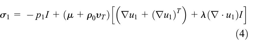
where subscripts “0” and “1” represent the time averaged and acoustic perturbation variables, respectively,
Sound-absorbing material domain
For the two-pass perforated hybrid mufflers in the present work, considering the extremely low flow velocity of air entering the sound-absorbing material through the perforation when inlet velocity is low, the effects of air flow inside the sound-absorbing material on sound propagation can usually be ignored. Therefore, there is the following relationship in the sound-absorbing material domain:

The sound-absorbing materials can be equivalent as fluids with complex sound speed
Substituting equation (5) into equations (2)–(4) and replacing the density


It can be seen that the characteristics of sound propagation in sound-absorbing material depend on the complex sound speed
Numerical method
Figure 1 shows the computational model of two-pass perforated hybrid mufflers, where the air and sound-absorbing material domain are separated by perforations. The glass fiber with filling density 151.4 kg/m3 is used as sound-absorbing material, which has been illustrated in reference. 12 The dimensions of the muffler are D = 132 mm for inner diameter of expansion chamber, d = 29 mm for inner diameter of inlet and outlet tube, L = 456 mm for length of expansion chamber. The l = 183 mm represents the length of the outlet pipe inserted into the left chamber, while other specific dimensions of the muffler and the perforations distribution are illustrated in the literature. 12 The perforations are built physically and meshed in the simulations to study the influence of perforated acoustic impedance on acoustic attenuation behavior. The simulation of perforation is helpful for mufflers design when perforated impedance formulae is limited in some case.
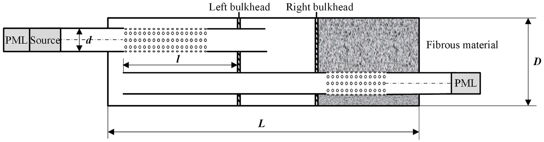
Computational domain of two-pass perforated hybrid mufflers.
RANS simulation of time averaged flow
The time averaged flow is calculated by using incompressible RANS along with Realizable
Because the sound-absorbing material has influence on the time averaged flow in hybrid mufflers, the accurate model of sound-absorbing material is important for calculation of flow. The method for simulation of sound-absorbing involves introducing an additional momentum source term into the momentum equation. The source term consists of viscous loss and inertial loss, which is defined as 18 :

where

The static flow resistance R is used to obtain the viscous resistivity, and then the influences of sound-absorbing material on time averaged flow can be considered accurately. In the present work, the static flow resistance R is obtained by acoustic characteristics of sound-absorbing material at frequencies of 100 Hz. 24
The tetrahedral and prismatic elements are adopted to discretize the flow domain due to the good adaptability,16,18 as shown in Figure 2. The growth rate of mesh not exceeds 1.2, and the maximum size of mesh is about 5 mm. The normal distance between the first internal point and walls is approximately 0.2 mm, and about 5-layer elements are arranged along the walls of perforations. 16
Fluidic mesh.
LNSEs acoustic computation
The frequency domain LNSEs in air and sound-absorbing domain are computed by employing finite element method, which is implemented by using the multi-physical software COMSOL Multiphysics version 5.4. It can be inferred from previous derivations that the sound propagation in sound-absorbing material in the presence of flow depend on the complex sound speed and density. Typically, the complex wavenumber and impedance ratio are used to represent the acoustic characteristics of sound-absorbing materials, which has a definite relationship with complex sound speed and density. The glass fiber with filling density 151.4 kg/m3 is selected as the sound-absorbing material, and the acoustic characteristics of the material has been investigated in detail in previous literature. 12 As acoustic excitation, plane wave is applied to the sound source area as shown in Figure 1. Due to the smaller inner diameter, that plane wave propagates in the inlet and outlet tubes (cut-off frequency is Hz for all configuration used in the present works), and the relationship between sound pressure and sound particle velocity can be expressed as:

where superscripts “+” and “−” represent the incident and reflected waves, respectively. The extraction position of acoustic perturbation variables on the right side of equation (10) should be far enough from the inlet and outlet of the muffler to avoid the influence of vortex waves. In order to further reduce numerical errors, the sound pressure and particle velocity are averaged on the cross-section area of the inlet and outlet tubes. To efficiently reduce the length of computational domain, the perfectly matched layer (PML) is arranged at both upstream and downstream ends, and then the transmission loss can be calculated by1,2:
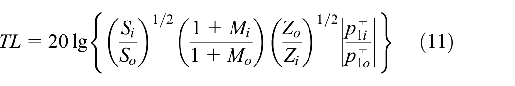
where subscripts “i” and “o” denote the inlet and outlet of muffler, respectively,
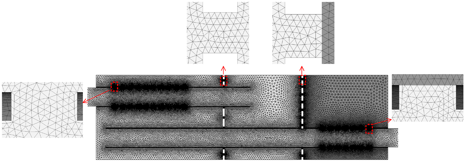
Tetrahedral and prismatic elements are used to discretize acoustic domain, as shown in Figure 3. The size of the acoustic mesh should meet the resolution of sound and vortex waves, 19 and the maximum size of mesh is approximately 10 mm. To accurately map the mean flow variables to acoustic mesh, the boundary layer is arranged, where the normal distance between the node of the first layer and the wall does not exceed the distance when solving the flow field.19–22 With consideration of the complex structure of the muffler, about 10-layer elements are arranged along normal direction of orifices. About 4-layer elements are arranged along the walls of perforation on inlet and outlet wall. The total number of mesh is 761,805, and the amount of mesh vertices is 270,901.

Acoustic mesh.
Method validation
In order to verify the correctness of LNSEs in calculating transmission loss of the two-pass perforated hybrid muffler in the presence of non-uniform flow, predictions are compared with measurements,12,14 as shown in Figure 4. It is to note that the upper frequency of measurements is 1200 Hz, except for the case at Mach number M = 0.05. It can be seen that the LNSEs predictions show good agreements with measurements in frequency range of interest, which validated the correctness of LNSEs method in predicting the transmission loss of the two-pass perforated hybrid muffler in the presence of complex airflow. The deviations between measurements and predictions may be attributed to the inhomogeneity of sound-absorbing material caused by manual filling and lower signal-to-noise ratio due to the limited power of sound source at Mach number M = 0.1.

Comparison of measured and predicted transmission loss of two-pass perforated hybrid muffler at different Mach number: (a) M = 0, (b) M = 0.05, and (c) M = 0.1.
Results and analyses
The perforated hybrid mufflers are desirable device for noise control engineering, where the complex airflow is usually formed inside the mufflers. Considering that the effect of perforations and convection on acoustic attenuation performance of hybrid mufflers has been investigated,12,14 the present work studies the effect of complex flow including convection and turbulence on the acoustic attenuation behavior of the mufflers. The effect of Mach numbers on transmission loss of mufflers with different filling densities and perforated components will be discussed, respectively.
Effect of Mach number for mufflers with different filling densities
The glass fibers with filling densities 100 and 200 kg/m3 are also filled in the hybrid muffler, where the acoustic characteristics of these sound-absorbing material have been published. 25 Figure 5 presents the influence of flow on the transmission loss of hybrid mufflers with different filling densities. The influence of flow on transmission loss of mufflers is not obvious with increasing the filling densities. The complex airflow increases the acoustic attenuation of the two-pass perforated hybrid muffler in the lower frequency range. At higher frequencies, there is no obvious trend to follow for transmission loss variation. The reason for these phenomena may be attributed to the complexity of perforated acoustic impedance in the presence of non-uniform flow.25,26 For filling density 200 kg/m3, the transmission loss reaches peak near 800 Hz at M = 0.05, which may be attributed to combined effect of acoustic impedance of all perforated components.

The effect of Mach number on transmission loss of the mufflers with different filling densities: (a) 100 kg/m3, (b) 151.4 kg/m3, and (c) 200 kg/m3.
Effect of Mach number for mufflers with various perforated components
Figure 6 shows the computational domain of two-pass perforated hybrid mufflers with different perforated components, where the baseline is referred to the configuration with perforations on the all bulkheads and inlet tube. For all configurations, the filling density of glass fiber is 151.4 kg/m3. Figure 7 compares the effect of Mach number on transmission loss of the hybrid mufflers. It can be clearly seen that the effect of airflow on acoustic attenuation performance of the mufflers is complex.

The computational domain of mufflers with different perforated component: (a) baseline, (b) solid left bulkhead, (c) solid right bulkhead, (d) solid all bulkhead, and (e) solid inlet tube.

The effect of flow on acoustic attenuation performance with various configurations: (a) baseline, (b) solid left bulkhead, (c) solid right bulkhead, (d) solid all bulkhead, and (e) solid inlet tube.
With Mach number increases, the acoustic attenuation performance is improved for baseline configuration, whereas the transmission loss decreases at the lower frequencies when removing the perforation on left bulkhead or all bulkhead. For the configuration with solid right bulkhead, the airflow reduces transmission loss at the firs peak frequency, while it is difficult to follow the influencing trend at higher frequencies. When removing the perforation on inlet tube, transmission loss at first peak frequencies decreases as the Mach number increases.
In conclusion, the effect of complex airflow on transmission loss of all configurations can be manifested as that: (1) the acoustic attenuation performance at lower frequencies is improved for mufflers with perforation on all bulkheads and inlet tube, while the low-frequency resonance peak lowers for mufflers with solid bulkhead(s) or inlet tube, (2) the influences of flow on acoustic attenuation performance in the medium and higher frequency range are not obvious for all configurations. Compared with other configurations, the baseline has good connectivity because of the perforations on all components, and then the sound wave reflects back and forth between chambers, which leads to the similar characteristics of simple expansion chamber in the lower frequency range. 1 The flow increases transmission loss of the muffler at the lower frequencies. Each small orifice on bulkheads forms a Helmholtz resonator with the end chamber, and then each resonant cavity is coupled to form a complete parallel resonator.1,2 Due to solid bulkhead(s), it is equivalent to decrease of the neck area of the resonator and increase of the neck length, which causes resonance shifting to lower frequency.1,2,8 The interaction of flow and sound wave leads to the decrease of acoustic resistance of the resonators. 27 Thus for the muffler with solid bulkhead(s), the low-frequency resonance peak are lowered due to the effect of the flow-acoustic coupling. For the muffler with solid inlet tube, the left chamber and bulkhead form a Helmholtz resonator, and the flow plays an important role in lowering low-frequency resonance peak. For all configurations, the transmission losses at medium and high frequencies are mainly influenced by combined effects of the sound-absorbing material and acoustic impedance of perforations. It is difficult to follow an obvious trend for the transmission loss due to complexity of acoustic impedance in the presence of flow, which is similar to the conclusion in literate. 16
Conclusions
A numerical method based on three-dimensional frequency-domain LNSEs considering eddy viscosity are firstly applied to accurately and quickly predict the acoustic attenuation performance of two-pass perforated hybrid mufflers in the presence of complex airflow. The calculations of transmission loss of perforated hybrid mufflers can be divided in two steps: to obtain the time averaged flow variables by solving RANS equations and to compute acoustic perturbation variables based on frequency domain LNSEs. Later, the transmission losses of perforated hybrid muffler are predicted by the present method and compared with measurements. The good consistencies between predictions and measurements of transmission losses of the mufflers validated the correctness of the LNSEs. Last, the present method is applied to investigate the effect of airflow on transmission losses of two-pass perforated hybrid mufflers with different filling densities and perforated components. The complex airflow increases transmission loss for the mufflers with various filling densities at lower frequencies in general. For the mufflers with solid bulkhead(s) or inlet tube, the airflow lowers low-frequency resonance peak.
Footnotes
Handling Editor: Chenhui Liang
Declaration of conflicting interests
The author(s) declared no potential conflicts of interest with respect to the research, authorship, and/or publication of this article.
Funding
The author(s) disclosed receipt of the following financial support for the research, authorship, and/or publication of this article: The authors would like to acknowledge the support of Key R&D project of Heilongjiang Province, China.