
Abstract
The one-dimensional analytical approach is developed to predict and analyze the acoustic attenuation performance of three-pass perforated tube muffler with perforated bulkhead(s) and validated by comparing the transmission loss results from one-dimensional analytical approach and finite element method. The one-dimensional analytical approach is then used to investigate the effect of perforated bulkhead(s) on the acoustic attenuation performance of three-pass perforated tube reactive and hybrid mufflers. The results indicated that perforates on the bulkhead may change the resonant frequency of the three-pass perforated tube reactive muffler, and the resonance frequency is shifted to higher frequency with the increase in the porosity of perforation. The sound-absorbing material filling in the middle chamber may improve the acoustic attenuation performance of the mufflers from middle to high frequencies, while the acoustic attenuation performance around the resonance frequencies is lowered somewhat; therefore, a flatter acoustic response may be formed for the hybrid muffler than the reactive muffler.
Keywords
Introduction
Three-pass perforated tube mufflers are widely used in automotive exhaust systems to reduce the engine exhaust noise. Munjal1,2 and Selamet et al. 3 presented the one-dimensional (1D) frequency-domain approaches, and Dickey et al. 4 developed the 1D time-domain approach to predict the acoustic attenuation performance of the typical three-pass perforated tube mufflers. For a prototype muffler, their predictions of transmission loss agree reasonably well with the experiments within the plane wave range. Ji and Selamet 5 employed the three-dimensional (3D) boundary element method (BEM) to predict the acoustic attenuation performance of the typical three-pass perforated tube muffler, and the BEM predictions agree well with experiments for a prototype muffler in the frequency range of interest. Sánchez-Orgaz et al. 6 proposed for the acoustic analysis of automotive silencers including a perforated duct with uniform axial mean flow and an outer chamber with heterogeneous absorbent material in terms of 3D finite element method (FEM). Recently, Ji and Fang 7 developed the 1D analytical approach to predict the acoustic attenuation performance of the three-pass perforated tube muffler with end-resonator, and the predictions of transmission loss are validated by comparing the FEM and BEM results. The main advantage of 3D numerical methods is that the effect of 3D sound field in the muffler is considered, and the accurate prediction of acoustic attenuation performance of muffler may be obtained at higher frequencies. However, the 3D numerical methods will take long computational time for the acoustic analysis of muffler, while the 1D analytical approach may capture the acoustic response of muffler quickly and, therefore, became an effective tool for the acoustic analysis of muffler, especially in the stage of initial design of muffler.
In order to adjust the resonance frequency and acoustic response of the three-pass perforated tube muffler, the bulkhead(s) may be perforated to form a new kind of muffler called as the three-pass perforated tube muffler with perforated bulkheads. The objective of this study is to develop a 1D analytic approach to predict the acoustic attenuation performance of this kind muffler and then to investigate the effect of perforated bulkhead(s) on acoustic behavior of the reactive and hybrid mufflers.
Theory
Following the works of Selamet et al.,
3
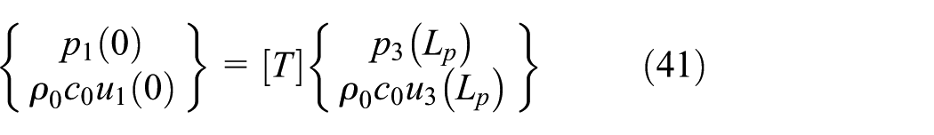
the relationship of sound pressures and particle velocities at the inlet (

where

Three-pass perforated tube muffler with left-perforated bulkhead (the case of

Three-pass perforated tube muffler with right-perforated bulkhead (the case of

Three-pass perforated tube muffler with both perforated bulkheads (the case of
Muffler with left-perforated bulkhead
For uniform perforations in the perforated bulkhead, the velocity and sound pressure on the left and right sides of the perforate may be expressed as

where
Equation (2) can be written as

where
The three-pass perforated tube muffler with left-perforated bulkhead is shown in Figure 1. For the case of


where
Similarly, the following expressions are obtained by the transfer matrix method for the case of
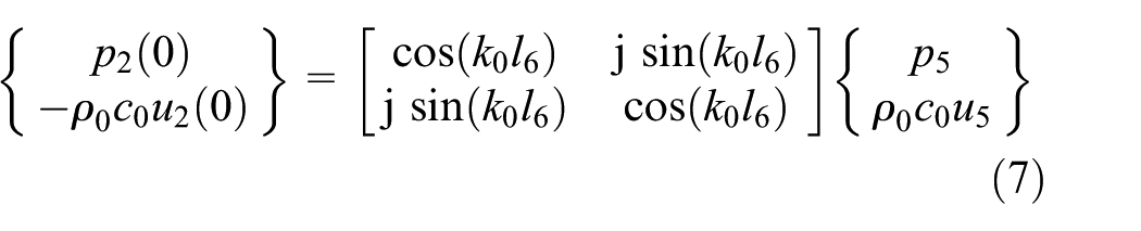


where
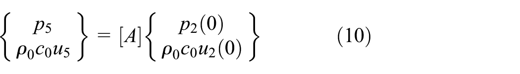
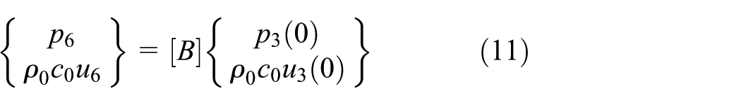
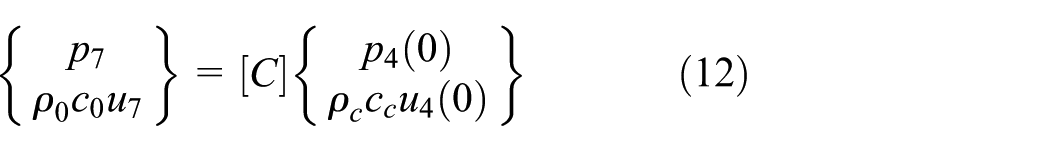
Expressions (4)–(6) and (7)–(9) may be written as
On the interface, the continuity conditions of sound pressures and particle velocities are


where
For the right cavity, the following expression may be obtained using the transfer matrix method

for the case of
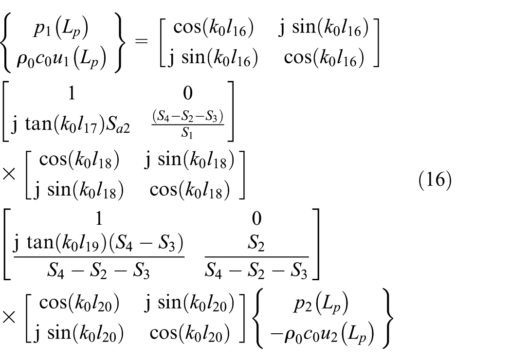
for the case of
Expressions (15) and (16) are rewritten as

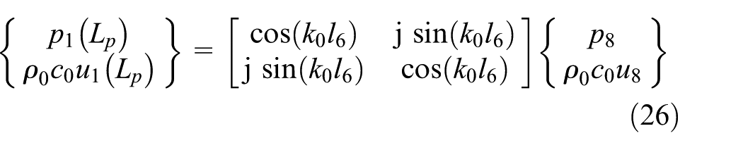
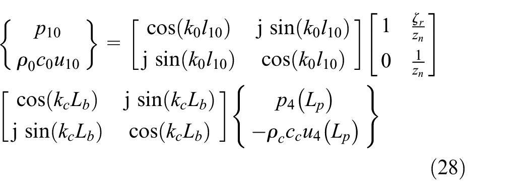
For the expansion chamber, the following relation may be obtained

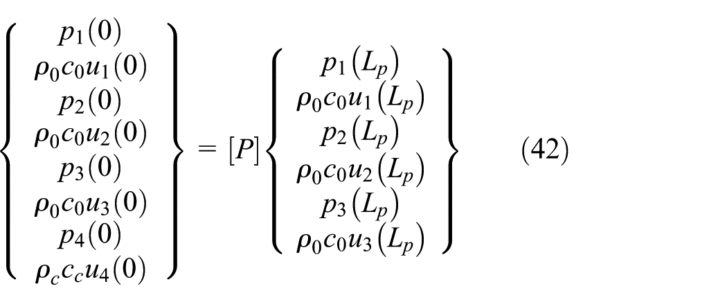
Substituting equations (13) and (18) into equation (1) yields

where

Writing matrix
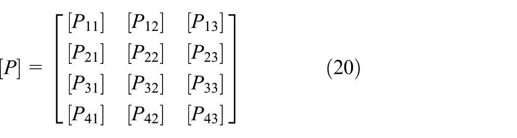
where
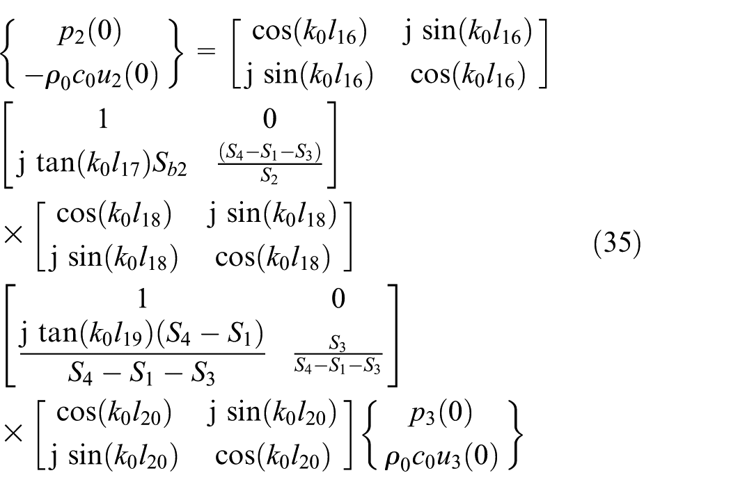
Substituting equation (17) into equation (19) then gives

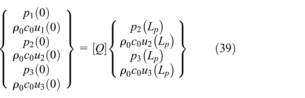
Substituting equations (13) and (14) into equation (21) yields the following relationship between the inlet and outlet of muffler
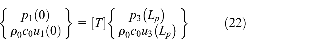
where

Muffler with right-perforated bulkhead
Three-pass perforated tube muffler with right-perforated bulkhead is shown in Figure 2. For the case of


where
Similarly, the following expressions are obtained by the transfer matrix method for the case of

where
Expressions (23)–(28) may be written as


On the interface, the sound pressure and velocity continuity conditions are


where
For the left cavity, the following expression may be obtained using the transfer matrix method

for the case of
for the case of
Expressions (34) and (35) may be rewritten as

For the expansion chamber, we may have

Substituting equations (32) and (37) into equation (1) then gives

where

Substituting equations (32) and (33) into equation (38) yields
where

Matrix

where
Finally, substituting equation (36) into equation (39) obtains the following relationship between the inlet and outlet of muffler
where
Muffler with both perforated bulkheads
Three-pass perforated tube muffler with both perforated bulkheads is shown in Figure 3. Based on prior analyses of sections “Muffler with left-perforated bulkhead” and “Muffler with right-perforated bulkhead,” expressions (10)–(12), (29)–(31) as well as the boundary condition expressions (13), (14), (32), and (33) are still valid.
Substituting equations (14) and (33) into equation (1) yields
where
Substituting equations (13) and (32) into equation (42) yields

where

Substituting equation (13) into equation (32) obtains the following relationship between the inlet and outlet of the muffler

where

Acoustic properties of perforation and sound-absorbing material
For the perforated facing, one side of which is the air and another side is the sound-absorbing material, the following expressions for the specific acoustic impedance of perforation are adopted 9


where
Ji and Fang 10 reviewed the existing expressions for the end correction coefficient and acoustic impedance and indicated that following Ingard’s 11 expression for the end correction coefficient may be the most suitable for the prediction of acoustic attenuation behavior of perforated tube silencers; therefore, it is adopted in this work

where
Lee and Selamet
12
presented the following expressions to calculate specific impedance and wave number of fibrous material with filling destiny


where
Results and discussion
Validation
The three-pass perforated tube mufflers with perforated bulkheads are shown in Figures 1–3, and the relative positions of inlet, center, and outlet tubes are shown in Figure 4. The dimensions of the muffler are selected as follows:

The relative positions of inlet, center, and outlet tubes in the muffler.
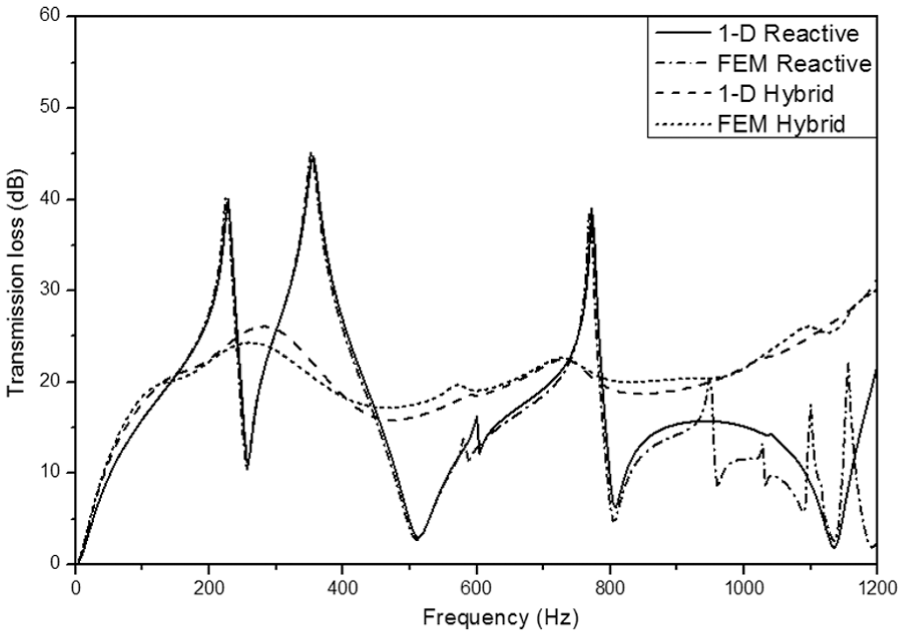
Figures 5–7 compare the transmission loss predictions of the reactive and hybrid (with fibrous material filling in the center chamber) mufflers with left-perforated bulkhead, right-perforated bulkhead, and both perforated bulkheads, respectively, from the 1D analytical approach and 3D FEM.

Transmission loss of the reactive and hybrid mufflers with left-perforated bulkhead (porosity

Transmission loss of the reactive and hybrid mufflers with right-perforated bulkhead (porosity
Transmission loss of the reactive and hybrid mufflers with both perforated bulkheads (porosity
For the reactive mufflers with perforated bulkhead(s), Figures 5–7 indicate that the 1D analytical solution agrees reasonably well with the FEM predictions up to about 950 Hz and deviates at higher frequencies. The differences between transmission loss predictions from the 1D analytical approach and 3D FEM may be attributed to the local nonplanar wave effects, and the deviation at higher frequencies may be attributed to the effect of higher order modes. The cutoff frequency is determined as 964 Hz using FEM calculation for this muffler. Beyond the cutoff frequency, the multidimensional wave may propagate and affect the acoustic attenuation performance of the mufflers; therefore, the 1D analytical approach is not suitable anymore. For the hybrid mufflers with perforated bulkhead(s), reasonable good agreements are observed between both approaches in the frequency range of interest. Since the existence of sound-absorbing material, the effect of higher order modes is limited even beyond the cutoff frequency, and good agreements were observed in the whole frequency range for hybrid silencers.
Acoustic performance analysis of muffler
Figure 8 compares the transmission loss predictions of the reactive mufflers with solid bulkheads and one and two perforated bulkheads from the 1D analytical approach. Compared to the muffler with solid bulkheads, the perforated bulkhead(s) changed the resonance frequency and acoustic response throughout frequency of interest.

Transmission loss predictions of the three-pass perforated tube muffler with solid, left-perforated, right-perforated, and both perforated bulkheads.
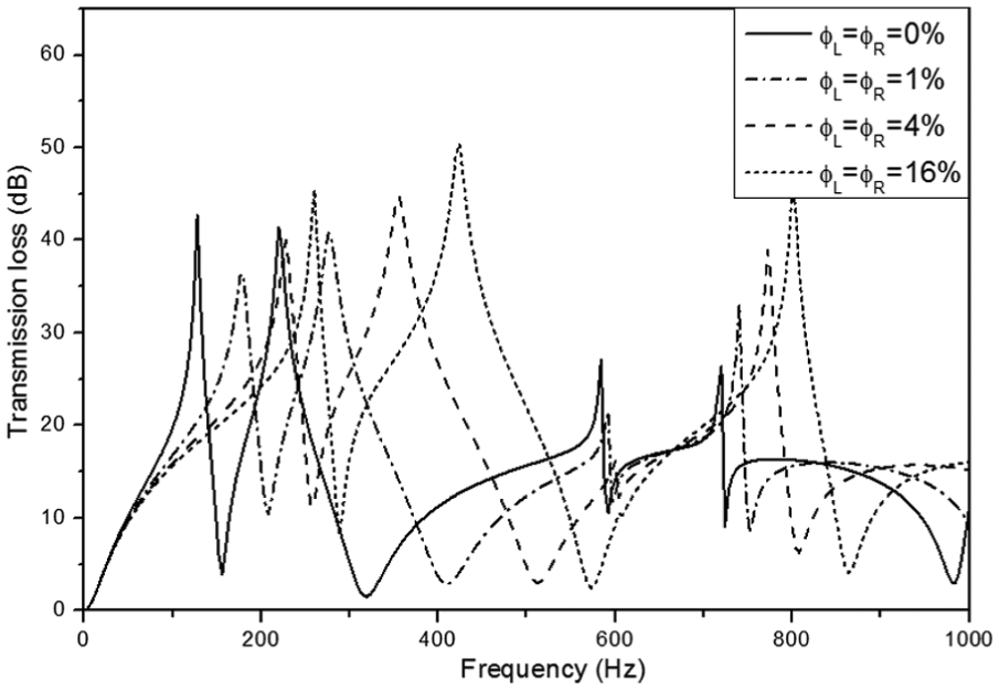
The effect of perforate porosity on the acoustic attenuation performance of the reactive muffler with left-perforated bulkhead (holes diameter

Effect of porosity on acoustic attenuation performance of three-pass perforated tube muffler with left-perforated bulkhead.
Figure 10 shows the effect of different porosities of the right-perforated bulkhead (hole diameter

Effect of porosity on acoustic attenuation performance of three-pass perforated tube muffler with right-perforated bulkhead.
Figure 11 illustrates the effect of different porosities of the reactive mufflers with both perforated bulkheads (hole diameter
Effect of porosity on acoustic attenuation performance of three-pass perforated tube muffler with both perforated bulkheads.
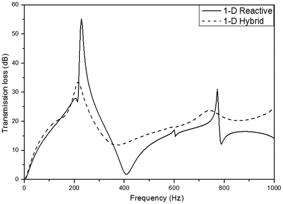
Figures 12–14 examine the effect of sound-absorbing material filling in the middle chamber on the acoustic attenuation performance of the mufflers. It may be seen that the sound-absorbing material decreases the transmission loss around the resonance frequencies and improve the acoustic attenuation at most frequencies. As a result, the transmission loss curve of the hybrid muffler is flatter than that of the corresponding reactive muffler.

Effect of sound-absorbing on acoustic attenuation performance of three-pass perforated tube muffler with left-perforated bulkhead.
Effect of sound-absorbing on acoustic attenuation performance of three-pass perforated tube muffler with right-perforated bulkhead.

Effect of sound-absorbing on acoustic attenuation performance of three-pass perforated tube muffler with both perforated bulkheads.
Conclusion
The 1D analytical approach based on the plane wave propagation is presented to determine and analyze the acoustic behaviors of three-perforated tube reactive and hybrid mufflers with perforated bulkhead(s). The transmission loss predictions from the 1D analytical approach and FEM are compared to validate the 1D approach for the reactive and hybrid mufflers. The results indicated that 1D analytical approach agrees reasonably well with FEM until up to the plane wave cutoff frequency. Perforates on the bulkheads may change the resonant frequency of the three-pass perforated tube mufflers, and the resonance frequency is shifted to higher frequency with the increase in the porosity of perforation. Increasing the porosity of the bulkheads within a certain range may improve the acoustic attenuation behavior of the muffler in specific frequency range. The sound-absorbing material filling in the middle chamber decreases the acoustic attenuation around the resonance frequencies and improves the acoustic attenuation performance at most frequencies to lead a flatter acoustic response of the hybrid mufflers than the corresponding reactive mufflers. The effects of mean flow on the acoustic attenuation performance of mufflers with perforated components are important and may be considered using the proper expression of perforate impedance.
Footnotes
Academic Editor: Hongwei Wu
Declaration of conflicting interests
The author(s) declared no potential conflicts of interest with respect to the research, authorship, and/or publication of this article.
Funding
The author(s) disclosed receipt of the following financial support for the research, authorship, and/or publication of this article: This article is funded by The National High Technology Research and Development Program of China (“863” Program) and the funding number is 2014AA041502.