
Abstract
A innovative single-actuated ultrasonic elliptical vibrator was proposed in this study. The single-actuated ultrasonic elliptical vibrator is composed of a sandwich longitudinal piezoelectric transducer and a combined-beam horn. The combined-beam horn consists of a cylindrical metal, a straight beam, and a skew beam. Attributed to its special structure, an elliptical vibration trajectory was generated at the output end of the combined-beam horn. Based on the mechanical vibration theory, the mathematical modeling of the combined-beam horn was carried out, which concluded the vibration characteristic at the output end of the combined-beam horn. The vibration characteristic of the single-actuated ultrasonic elliptical vibrator was investigated using the finite element method. An experimental set-up was built up to verify the proposed mathematical modeling of the combined-beam horn and study the vibration characteristic of the single-actuated ultrasonic elliptical vibrator prototypes. Furthermore, the ultrasonic elliptical vibration trajectory was tested at the output end of the combined-beam horn, and the experimental elliptical vibration trajectory is in good agreement with the theoretical analysis. It is expected that this type of single-actuated ultrasonic elliptical vibrator can be used in numerous power ultrasonic applications, such as ultrasonic turning, milling, planning, drilling, grinding, polishing, welding, and motor and other fields.
Introduction
Ultrasonic elliptical vibration is widely employed in turning, milling, planning, drilling, grinding, polishing, welding, and motor and other fields.1–9 It has been successfully applied to precision cutting due to its superior performance, low cutting force, high-quality surface finish, and long tool life. At present, most ultrasonic elliptical vibration systems are driven by two actuated sources which undergo phase shift. Commonly used vibration modes include longitudinal vibration, torsional vibration, bending vibration, and radial vibration. Two of the four vibration modes are selected as the actuated sources, and the two types of piezoelectric ceramics and the corresponding power supply are used in elliptical vibration systems.2,7,8,10–14 For a double-actuated elliptical vibration transducer, the wave velocity and wavelengths are different in different kinds of vibration, the resonant frequencies of two vibrations must be the same or close, and the phase shift between the two vibrations should be at or close to 90°, so the design and realization of a double-actuated elliptical vibration transducer are very difficult. For the above reasons, the control system needs to provide two power supply signals, and the phase shift between the two power supply signals should be at or close to 90°, so the control system of a double-actuated elliptical vibration transducer more complex than that of a 1D ultrasonic vibration transducer.15–18
It has been proved practically that the vibration system, with some special structure, can produce elliptical vibration trajectory by one-dimensional (1D) actuated signal.19–23 A single-actuated ultrasonic elliptical vibrator (SAUEV) usually consists of a special structure horn and a 1D ultrasonic vibration transducer. It only needs an ultrasonic power supply to actuate. Different SAUEVs have their own vibration characteristics and applicable conditions. Compared to common ultrasonic elliptical vibration systems, SAUEV uses a single longitudinal mode of vibration, which is easier to design and achieve large amplitude vibration. However, phase shift and amplitude ratio cannot be freely controlled in SAUEV. Nonetheless, SAUEV has more advantages including simple structure, small volume, simple control circuit, low cost, easy to manufacture, easy to assemble and adjust, and so on.1,2,19–23 These advantages make it play an important role in precision cutting. Therefore, it is of high theoretical and engineering value.
Brinksmeier and Glabe 19 and Li and Zhang 20 built two similar single-actuated ultrasonic elliptical vibration cutting systems by adding the mass tool deviation from the axis of a longitudinal vibration ultrasonic cutting system. The off-center mass tool caused a bending vibration mode of the longitudinal vibration ultrasonic cutting system. The bending and the longitudinal vibrations produced an elliptical tool vibration locus. Changing the position of the mass relative to the tool permitted some adjustment of the tool locus geometry. Li and Zhang 21 presented a single-driven ultrasonic elliptical vibration cutting system by opening tilted slots on the horn of a longitudinal vibration ultrasonic vibrator and proved the theoretical analysis results through finite element method (FEM) and experiments. Yin et al. 22 constructed a single-actuated ultrasonic elliptical vibration cutting system by arranging three asymmetric grooves on the horn, and the elliptical vibration locus was inclined relative to the up-feed motion because of the phase shift between the bending and longitudinal vibrations.
An innovative SAUEV with simple structure consisting of a combined-beam horn (CBH) was proposed in this study. The CBH was connected to an ultrasonic longitudinal vibration transducer. Attributed to the special structure of the CBH, when the ultrasonic longitudinal vibration transducer was under the working mode, ultrasonic elliptical vibration trajectory was generated at the output end of the CBH. Based on the mechanical vibration theory, the mathematical modeling of the CBH was carried out, which concluded the vibration characteristic at the output end of the CBH. After fabricating a SAUEV prototype with a CBH, the characteristics of the output end of the CBH were investigated through experiments, and the ultrasonic elliptical vibration trajectory of the output end of the CBH was verified. Compared to previous designs, the output power and the vibration amplitude of the SAUEV with the CBH were found to be improved. Furthermore, the ultrasonic vibrator exhibits the advantages of high power capacity, high energy conversion efficiency, simple structure, high structural stiffness, easy to manufacture, low cost, and simple and stable performance of the control system. It offers the research reference for the further expansion of the application and popularization of the SAUEV system in various fields.
Structure of the SAUEV
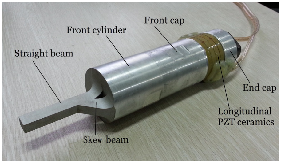
Figure 1 shows SAUEV composed of a CBH and a 1D longitudinal sandwich piezoelectric ultrasonic vibration transducer. The 1D longitudinal sandwich piezoelectric ultrasonic vibration transducer acts as the active actuated source, which includes an aluminum front cap, PZT-8 piezoelectric ceramics, electrodes, rear cap, flange and connecting screws, and it can be connected to the other device via the flange.
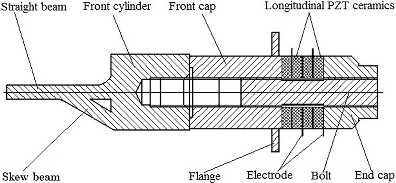
SAUEV with CBH.
The CBH is composed of a front mass, a straight beam, and a skew beam as shown in Figure 2. The front mass is an aluminum cylinder. The cross sections of the straight beam and the skew beam are rectangular. The straight beam is set at the front end of the front mass, which is coaxial with the front mass. The rear end of the straight beam is connected to the front end of the front mass, and the front end of the straight beam overhangs. The front end of the skew beam is connected to the middle of the straight beam, and the rear end of the skew beam is connected to the side of the front mass that deviates from the central axis. Natural arc transition is adopted between the front mass, the straight beam, and the skew beam, and the stress concentration may be reduced when adopting arc transition.
The CBH.
Mathematical modeling of the CBH
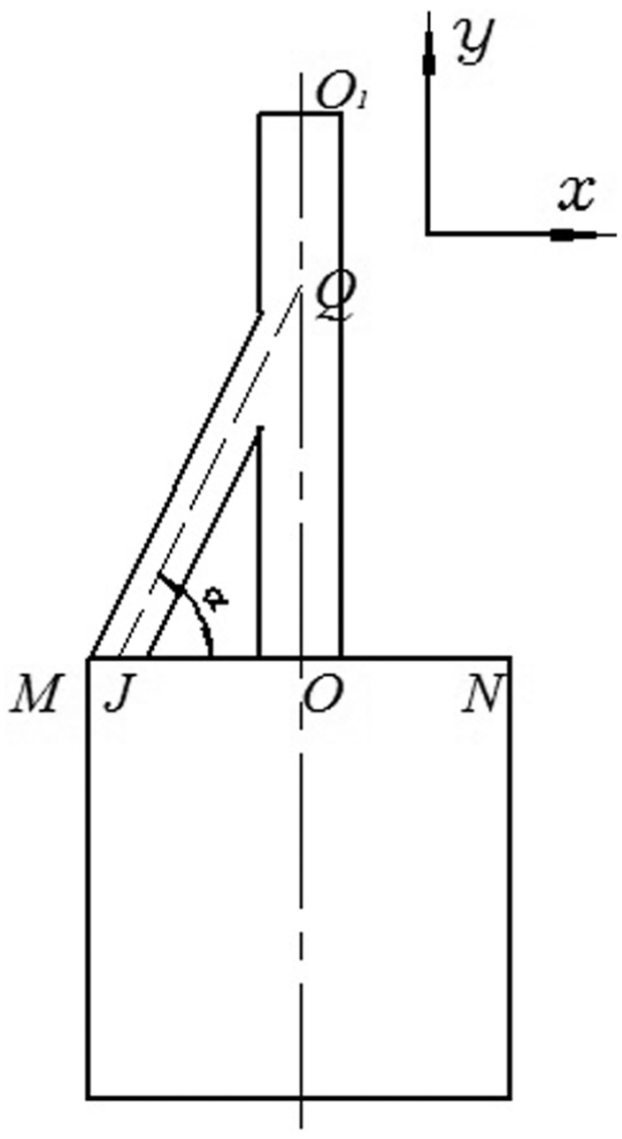
The thickness of the straight and the skew beam is more than their width. Considering that the bending vibration and deformation do not appear in the normal direction of the CBH as shown in Figure 2, we simplified the straight beam and the skew beam into equal diameter beams in two-dimensional coordinate plane. Based on the mechanical vibration theory, a simplified mathematical modeling of the CBH was carried out as shown in Figure 3.

The mathematical modeling of the CBH.
Assuming that the length of the straight beam OO1 is h, OQ is a, and OJ is b, then the angle between the straight and the skew beam is α

The point J at the bottom of the skew beam, and the point O at the bottom of the straight beam, the vibration equations of the points J and O in y direction can be expressed as equation (2)

where A is the vibration amplitude of the bottom for the straight (O) and the skew beam (J), ω = 2πf is the angular frequency of the CBH, and f is the harmonic frequency of the CBH.
The longitudinal vibration y01(t) can be decomposed into two components v(t) and u(t), v(t) is the longitudinal vibration component along the axis of the skew beam and u(t) is the bending vibration component perpendicular to the axis of the skew beam


According to the vibration theory for 2 degrees of freedom system under harmonic excitation, the vibration system of the skew beam can be established as shown in Figure 4.

Vibration system of the skew beam.
The motion differential equations of the skew beam in two directions can be described as follows 24

where
The steady-state response of the end Q of the skew beam is represented as follows

where


The propagation velocities of the longitudinal vibration wave v(t) and bending vibration wave u(t) are different in the same medium. The relationship between the two vibration velocities is represented as follows

where CT is the bending vibration wave velocity, CL is the longitudinal vibration wave velocity, and μ is Poisson’s ratio for the CBH.
The phase of the longitudinal vibration wave y02(t) was set as a reference. According to the propagation velocities of the longitudinal vibration wave v(t) and bending vibration wave u(t) in the skew beam, the phase shift between the longitudinal vibration wave y02(t) and the longitudinal vibration wave v(t) or the bending vibration wave u(t) can be written as follows

The straight beam of the CBH includes the OQ section with longitudinal vibration wave, the QO1 section with longitudinal vibration wave, and bending vibration wave. The steady response of the longitudinal vibration wave y02(t) at the point Q is represented as follows

where

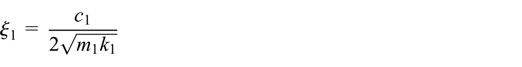
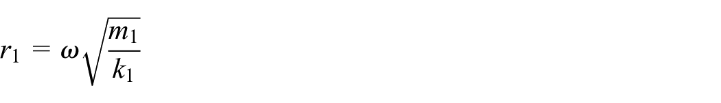
m
1 is the equivalent mass of the straight beam OQ, c1 is the damping coefficient, and k1 is the stiffness coefficient.

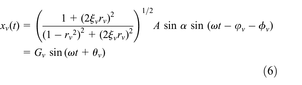
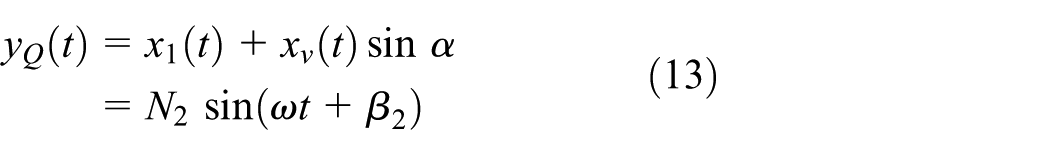
Figure 5 shows the components of three steady-state responses along the x- and y-axes at Q, xv(t) is the longitudinal vibration, xu(t) is the bending vibration, yQ(t) is the longitudinal vibration in y direction, xQ(t) is the bending vibration in x direction, xv(t) has bending vibration component (xv(t)cos α) in x direction and has longitudinal vibration component (xv(t)sin α) in y direction, and xu(t) has bending vibration component (–xu(t)sin α) in x direction, but has not longitudinal vibration component in y direction.
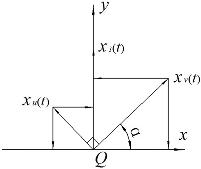
Components of three steady-state responses.
Here

and
where


and
The steady response of the vibration components

and

where


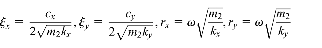
m
2 is the equivalent mass of the skew beam, cx, cy are the damping coefficients of the skew beam in the two directions x and y, respectively, and kx, ky are the stiffness coefficients of the skew beam in the two directions.

The elliptic equations can be obtained through simultaneous equations (14) and (15) by eliminating the time variable t
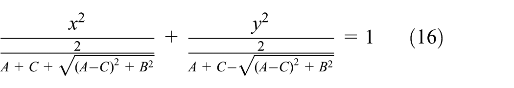
where


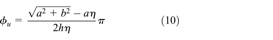
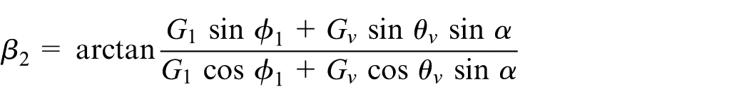
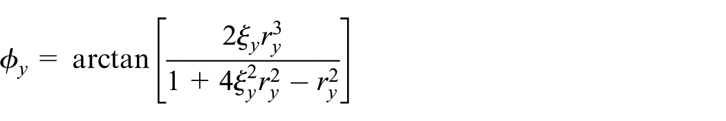
The phase shift

where
When the vibration amplitude A, the resonant frequency f, and the geometrical dimensions of the CBH are given, the vibration amplitudes in the x–y directions, phase shift between the vibration amplitudes, and the elliptical vibration trajectory of the output ends for the CBH can be computed based on equations (16) and (17).
Finite element analysis of the SAUEV
The modal analysis of the SAUEV was conducted using the ANSYS software. The main structural parameters of the CBH are as follows: a = 17 mm, b = 25 mm, and OO1 = 68 mm. The tool, adhesive, electrodes, bolt stress, and machining errors were neglected. The SOLID98 and SOLID95 element types were used for the SAUEV. The three kinds of material parameters and element types are given in Table 1. Zero voltages were applied at the electrodes. The solving range was set from 15,000 to 25,000 Hz, and the block Lanczos method was used for solving. Figure 6 exhibits the longitudinal and bending compound vibration modes, and the resonant frequency of 20.7685 kHz of the SAUEV. The vibration amplitude curves (Figure 7) along the axis of the SAUEV were achieved using POST1. Figure 7 exhibits the longitudinal and bending vibration at the end of the CBH output end, and the ratio between the bending vibration amplitude in X-direction and the longitudinal vibration amplitude in Y-direction is about 1:3. Considering the change rules of the variation amplitude along the central axis, the structure of the SAUEV can be optimized.
Material parameters and element types.

CBH: combined-beam horn.
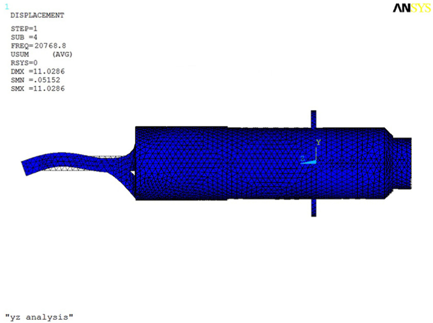
The vibration model of the SAUEV.
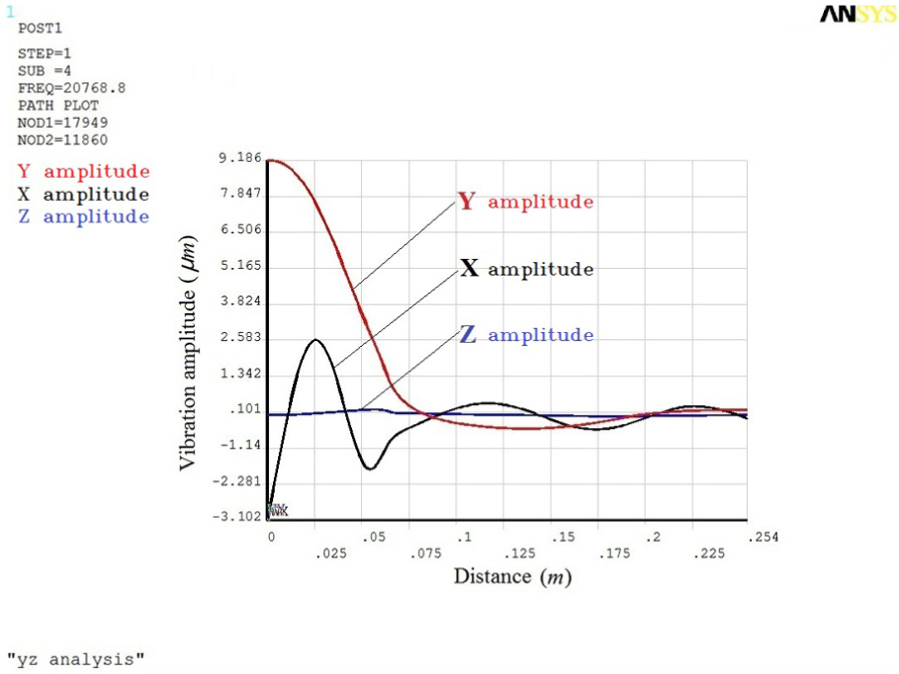
The vibration curve of the SAUEV.
By adding a sinusoidal voltage of 500 VP-P with a resonance frequency of 20.768 kHz to the SAUEV, the transient analysis was conducted using POST26, and the ANSYS simulation elliptical locus at the output end of the CBH was obtained. Based on the simulation curve of ANSYS, the fitting curve could be obtained as shown in Figure 8. The ratio between the major and minor axes of the elliptical vibration trajectory was about 1:3. The experimental phase shift between the x and y directions was 83°. Based on the results of the modal and transient analyses, it was concluded that the SAUEV could generate the ultrasonic elliptical vibration by applying only a single-driven vibrator. In this way, when a = 17, 25.5, 34, 42.5, and 51, respectively, the ANSYS fitting locus was obtained as shown in Figure 15.
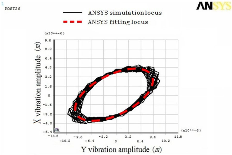
The elliptical vibration locus at the output end of the CBH.
Experimental set-up and conditions for the SAUEV
Five different CBHs were prepared with a = 17, 25.5, 34, 42.5, and 51, respectively, and their photograph is shown in Figure 9. When the CBH was mounted on the longitudinal vibration ultrasonic transducer, the SAUEV was formed. The prototype of the SAUEV is shown in Figure 10, and the sizes of the prototype of the SAUEV are listed in Table 2. Experiments for the SAUEVs with five different CBHs were carried out. The model of the ultrasonic power supply was YTP-1100S, its output frequency range was 15–60 kHz, output voltage range was 0–1200 V, and output current range was 0–3 A. The driving voltage for the SAUEVs was 400 VP-P, and the SAUEV could achieve a steady vibration state in 10 min.
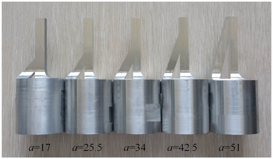
Photograph of the five CBHs.
Prototype of the SAUEV (a = 17).
The sizes of the prototype of the SAUEV.

PZT: lead zirconate titanate.
The schematic illustration of the experimental set-up for vibration characteristics tests is shown in Figure 11, and the photograph is displayed in Figure 12. The SAUEV is placed horizontally on the experimental platform. The plane formed by the axis of the straight beam and the skew beam is parallel to the top surface of the experimental platform. Optical fiber probe 1 of the MTI2100 optical fiber vibrometer is perpendicular to the output end of the CBH in the x direction. Optical fiber probe 2 is parallel to the output end in the y direction. The signals collected by the two optical fiber probes are processed using an MTI2100 optical fiber vibrometer and transmitted to the double-trace oscilloscope. The vibration amplitudes–time curves and the ultrasonic elliptical vibration trajectory can be displayed on the double-trace oscilloscope, and all the curves and data can be displayed and saved using the computer data acquisition system.

Schematic illustration of the experimental set-up.

Photograph of the experimental set-up.
Experimental results and discussion
Let the vibration frequency f = 20 kHz and the vibration amplitude A = 10 μm in equations (16) and (17), where A is the vibration amplitude of the bottom for the straight beam and the skew beam (Figure 3), a = 0–68 mm and b = 25 mm. The theoretical vibration characteristics data for the output end of the CBH were calculated using MATLAB software. The experimental and theoretical vibration amplitudes of the output ends for the five CBHs are shown in Figure 13. Clearly, the experimental vibration amplitudes are consistent with the theoretical vibration amplitudes, and the error is within 3%. We can see from the mathematical model of the CBH, the bending vibration of the output ends is transformed by longitudinal vibration through the skew beam. The larger the bending vibration amplitude, the higher the conversion efficiency from longitudinal vibration to bending vibration, as can be seen from Figure 13, the change rule of amplitudes of the bending vibration and longitudinal vibration shows the law of conversion efficiency from the longitudinal vibration to the bending vibration in five CBHs structures. In Figure 13, when a = 17 and 34, the bending vibration amplitudes are larger than that of the others. In other words, when a = 17 and 34, the conversion efficiency from longitudinal vibration to bending vibration is higher than that of the others and the experimental and theoretical vibration amplitudes of x direction are close to about half that of y direction, which indicates that the conversion efficiency is close to 50%. In these two cases, if the phase difference is appropriate, it is easier to form a standard positive ellipse. Different ellipses can be formed based on the different longitudinal vibration and bending vibration amplitudes, according to the change rule of amplitudes of the bending vibration and longitudinal vibration, the different CBHs can be selected for different ultrasonic application fields.

Experimental and theoretical vibration amplitudes.
Phase shift is one of the important parameters of elliptical vibration synthetic trajectory, and the size of the phase shift affects the tilt angle and the ratio of the major and minor axes of the elliptical vibration trajectory. When the phase shift is more than zero and less than π/2, the larger the phase shift, the smaller the ratio of the major and minor axes of the elliptical vibration trajectory, and then the elliptical vibration trajectory is closer to a standard ellipse. When the phase shift is more than π/2 and less than π, the larger the phase shift, the larger the ratio of the major and minor axes of the elliptical vibration trajectory, and then the elliptical vibration trajectory deviates from a standard ellipse. The experimental phase shifts of the five CBHs output ends and the theoretical phase shift simulation curve of the mathematical modeling are shown in Figure 14. The five phase shifts are less than π/2. When a = 17, the phase shift is the largest and the experimental phase shift between the x and y directions is 83°; thus, the ratio of the major and minor axes of the elliptical vibration trajectory is the smallest and the ultrasonic elliptical vibration trajectory is closest to a standard ellipse.

The theoretical phase shift curve and the five experimental phase shifts.
Refer to the vibration amplitudes and phase shifts of the five CBHs, the ultrasonic elliptical vibration trajectory of the five CBHs output ends was complexed by the double-trace oscilloscope as shown in Figure 15. Clearly, the experimental ultrasonic elliptical vibration trajectories are close to the theoretical ultrasonic elliptical vibration trajectories and ANSYS fitting trajectories. These results are consistent with the original hypothesis; however, the amplitudes and phase shifts are different in the five cases. Therefore, the ratios of the major and minor axes of the elliptical vibration trajectories are different; thus, different elliptical vibration trajectories with different eccentricities were obtained. When a = 17, the ultrasonic elliptical vibration trajectory is closest to a standard ellipse, and its amplitude improved by 22% compared with the SAUEV of Li and Zhang. 21

The theoretical and experimental ultrasonic elliptical vibration trajectories.
Figures 13–15 show a good agreement between the experimental data, the theoretical analysis, and the ANSYS simulation data, although there are some errors between the theoretical data, ANSYS simulation, and experimental results. There are several reasons for these errors, such as manufacturing errors of the horn, isotropic errors in the horn material, measuring error by the MTI2100 optical fiber. These error values are less than 3%, which is in a reasonable range. Therefore, the experimental results proved the rationality of the mathematical modeling for the CBH. The researches on the mathematical modeling, ANSYS simulation, and experimental research of the SAUEV can help us understand the change laws of the theoretical vibration characteristics for the output end, which has a high reference value for understanding the vibration characteristics of the SAUEV, and laid the foundation for the further study of SAUEV and CBH.
According to the different elliptical vibration trajectories of the output end, the SAUEV can be applied to different ultrasonic application fields, such as ultrasonic turning, milling, planning, drilling, grinding, polishing, welding, and motor and other fields. In this study, the research results of this SAUEV were applied to the ultrasonic elliptical vibration cutting and ultrasonic linear motor, and the photographs of the ultrasonic elliptical vibration cutting device and the ultrasonic linear motor are shown in Figures 16 and 17, respectively. The ultrasonic elliptical vibration cutting device with the SAUEV can reduce the cutting force and surface roughness compared to ordinary cutting, and the surface roughness of YAL12 workpiece can be reduced to Ra as low as 0.08 μm. 22 When the driving voltage for the SAUEV is 400 VP-P, the maximum moving speed of the ultrasonic linear motor with the SAUEV is 0.22 m/s.

Ultrasonic elliptical vibration cutting device.
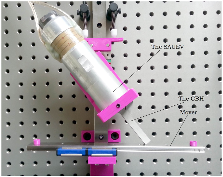
Ultrasonic linear motor.
Conclusion
The following conclusions can be drawn from the mathematical modeling and experimental results of the SAUEV with a CBH:
A novel SAUEV with a CBH was proposed in this study. The CBH consisted of a straight beam and a skew beam. This is a new method and idea for the realization of the SAUEV.
The mathematical modeling of the CBH was carried out. The theoretical vibration characteristic of the output end of the CBH was concluded. This offered a theoretical foundation for the research of the SAUEV.
An experimental study of the vibration characteristics for the SAUEV prototype was conducted. The experimental result shows a good agreement between the experimental data, ANSYS simulation, and the theoretical analysis. This proves theoretically and experimentally that a SAUEV can be successfully employed, and it provides a new reference for expanding the application field of ultrasonic elliptical vibration.
When a = 17, the experimental phase shift between the x and y directions was 83°, the ratio of the major and minor axes of the elliptical vibration trajectory was the smallest, and the ultrasonic elliptical vibration trajectory of the output end of the CBH was closest to a standard ellipse.
Footnotes
Handling Editor: Yangmin Li
Declaration of conflicting interests
The author(s) declared no potential conflicts of interest with respect to the research, authorship, and/or publication of this article.
Funding
The author(s) disclosed receipt of the following financial support for the research, authorship, and/or publication of this article: This research was financially supported by the National Natural Science Foundation of China (grant no. 51305286), Fundamental Research Funds for the Central Universities (grant no. CXZZ13_0151), Suzhou Science and Technology Projects (grant no. SYG201644), and Scientific Research Foundation of Suzhou University of Science and Technology (grant no. XKZ201502).