
Abstract
To add the splitter blades is an important technique to improve the pump performance characteristics. The effects of splitter blade on the pump performance and flow characteristics in a high-speed centrifugal pump were studied in this article. The numerical simulations were conducted to explore the steady and unsteady flows, and the simulation method was validated by the performance experiments on the full work conditions. The pump head was increased 10 m approximately, while the operating efficiency was raised nearly 4% by adding the splitter blades. The jet-wake structure in the outflow from the impeller was also improved obviously. The jetting flow increases greatly, and the flow separations in the blade passage are diminished. Moreover, the splitter blade obviously makes the turbulence kinetic energy distribution harmony and decreases the dissipation of turbulent kinetic energy to improve the flow stability. The pressure fluctuations in the frequency domain were proved to distribute more evenly in the complex impeller, which enhanced the steady flow in the pump.
Keywords
Introduction
The high-speed centrifugal pump is a blade-pump unit with compact structure and high pump head, which is widely used to pump oil or water in cutting-edge facilities such as aeroengine and petrochemical equipment. Expanding the operating condition and improving the operating efficiency of the pump have the practical significances for these facilities. The design method of “splitter blade” is to design the impeller with short blades spaced within long blades, which can improve effectively the unsteady flow in the blade passage to raise the impeller performance and the operating stability of pump. Not only does this method improve the performance characteristics of the high-speed centrifugal pump, but also has less effect on pump structure.
The design of splitter blade favors the reliever of the pressing flow in the impeller inlet to enhance the flowing uniformity of the fluid and minimize the probability of the occurrence of cavitation, which has been confirmed in the process of developing a powered pump of aero-engine. 1 The analyses for the effects of the geometric parameters of splitter blade on pump performance have been conducted and some design principles of splitter blade have been studied including biased position, blade number, blade-passage inlet diameter, and deflection angle.2–4 The inlet diameter of the short-blade passage can be set to the value of 0.5–0.7 times that of the long-blade passage. Meanwhile, the splitter blade should be arranged in the biased location with 1/10–1/8 grid pitch to the rotating direction. These principles have been confirmed by numerical simulations of the effects of the splitter blade with various numbers, positions, and inlet diameters on the pump performances and flow characteristics of the inner flow field. 5
Some optimization algorithms have been explored to design optimally the splitter blade used in pump. The design method for complex impeller was studied from the analyses of the fluid motion, and its aim is to raise the pump efficiency by constraints of anti-cavitation performance and stable pump performance.6–8 Moreover, a calculation formula for the splitter-blade number was established by aiming at refraining from the occurrence of the backflow in the outlet of impeller passage. 9
The flow behaviors inside the centrifugal pump with complex impeller were investigated by numerical simulation and inner flow test. Obvious jet-wake structure was observed in the outlet of the blade passage, and this structure was improved using splitter blades in the impeller.10,11 The effects of splitter blade on the pump head and pressure fluctuations in the impeller inlet and outlet were studied by the simulations.12,13 The pump head was increased by 20%, while the pressure fluctuation experienced an obvious decrease. Meanwhile, the particle image velocimetry was used to test the inner flow structure in the pump with complex impeller, and the rules of the influence of splitter blade on pump performance were proved.14,15 Also, the multi-factor orthogonal test was conducted to explore the design method of splitter blade by considering unsteady turbulence characteristics and energy losses.16–18
Some common theories have been explored and studied by previous researches, but a few of methods and techniques do not apply to some special pumps. In this article, a high-speed centrifugal pump with the rotating speed of 7600 r/min was studied, and its inner flow characteristics are different from that of the normal-speed pump. Two types of splitter blades were designed for exploring the effects of splitter blade on the pump performance and flow characteristics. The steady and unsteady flow fields in the model pumps were simulated numerically using a computational fluid dynamics (CFD) tool, and the simulation method was validated by the experimental analyses. This work provides some theoretical guidance for designing a high-speed centrifugal pump.
Materials and methods
Pump specifications
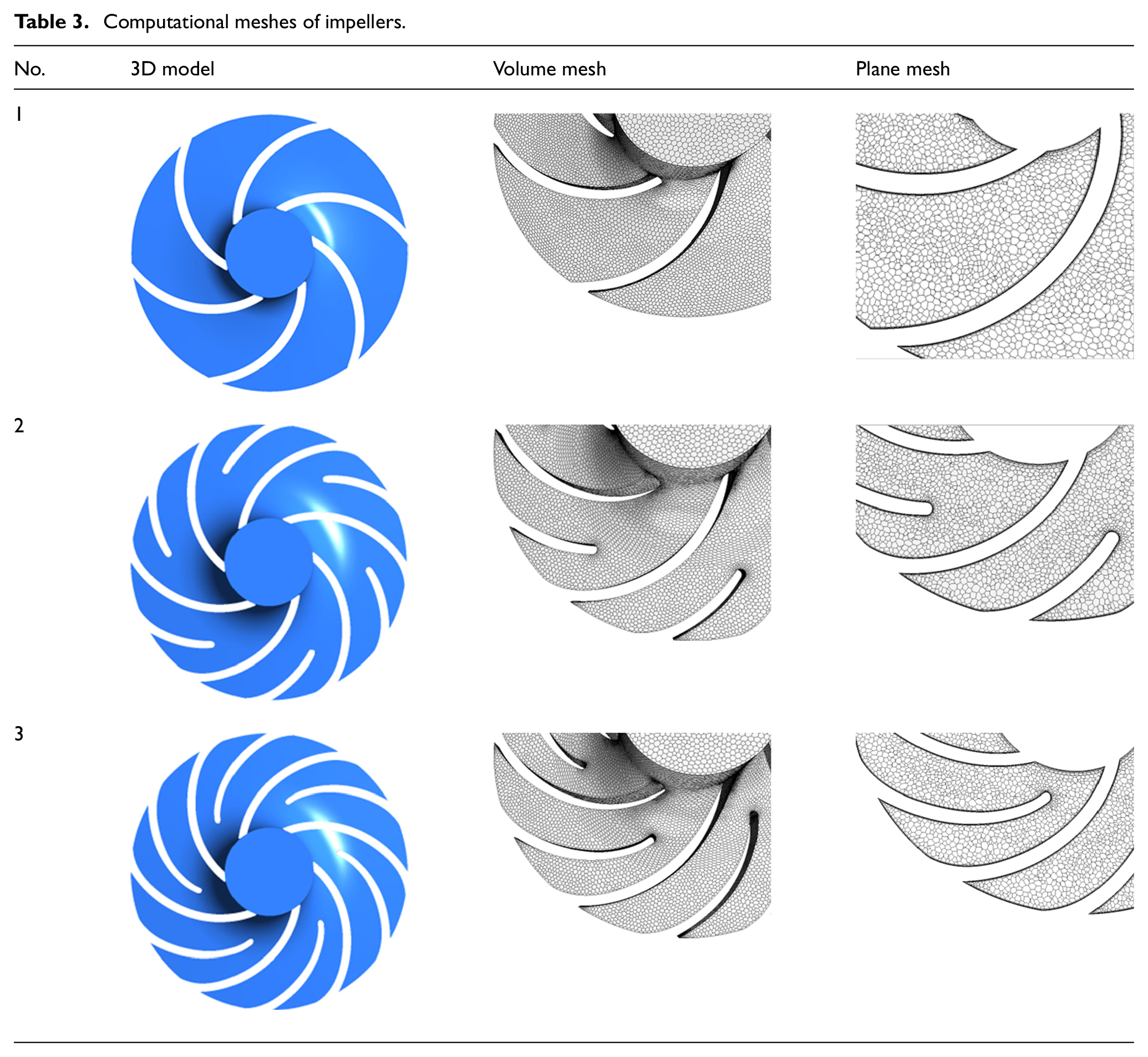
The centrifugal pump with the rotating speed of 7600 r/min was taken as the model pump in this article, and its nominal flow rate (QN) and total head (H) are 7.5 m3/h and 85 m, respectively. The main geometric characteristics of the pump are summarized in Table 1. Three impellers were designed to study the effects of splitter blade on the pump performance and inner flow characteristics. Table 2 shows the specific parameters of these impellers. The impeller 1 has six long blades, while the impellers 2 and 3 have six long blades and six splitter blades, respectively, but the splitter-blade inlet diameter of impeller 3 is shorter than that of impeller 2.
Geometric characteristics of model pump.

Pump impellers.

Experimental measurements
The experiment was designed and conducted to test the performance characteristics of the model pump. The testing apparatus was composed of a tested pump, an electromagnetic flowmeter, two pressure gauges, some regulating valves, pipeline, and the data acquisition system, as shown in Figure 1. The test facilities and measurement techniques for the pump performance testing are adequate to the specific requirements. 19 The working fluid used in the experiment was water at the 25°C. The flow rates were measured by an electromagnetic flowmeter with the accuracy ±0.3%. The pump inlet and outlet pressures were measured by pressure gauges with the uncertainty of ±0.25%.

Schematic diagram of experimental apparatus.
CFD methodology
The inner flow characteristics and periodic pressure fluctuations monitored in the model pump were studied and analyzed to explore the effects of the splitter blade on the pump performance characteristics. The computational domains of model pump were created for the numerical simulation, including inlet duct, impeller, volute, and outlet duct, as shown in Figure 2. The polyhedral meshes were generated for computational domains using the commercial software STAR-CCM+, and the grid details in rotating domains are partially shown in Table 3. Moreover, the mesh density was analyzed to verify the independent of the number of grid nodes for the solution. Figure 3 presents the simulated head of the model pump with impeller 1 under the different numbers of grid nodes, and the mesh with 1.2 million grid points was proven to be independent with significant computational saving.

Computational domain.
Computational meshes of impellers.
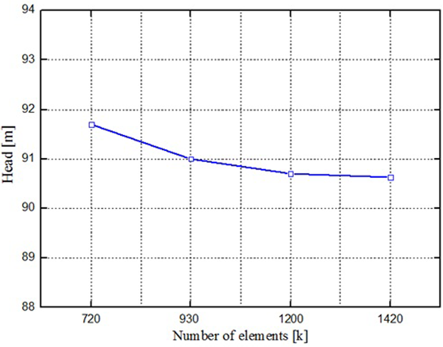
Mesh independence analysis.
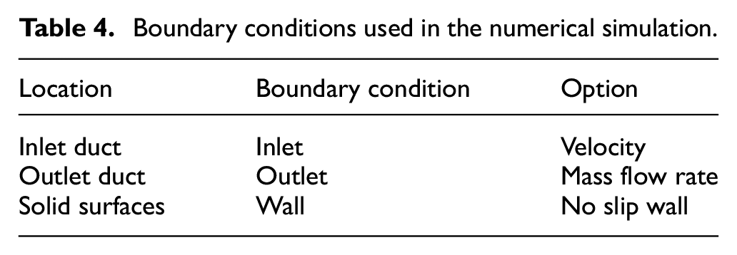
Three-dimensional steady and unsteady flow analyses were performed by numerical simulations using the general software ANSYS FLUENT. The steady flow was simulated with using the same computational domains with the unsteady simulations, and its results were taken as the initial conditions for the unsteady flow. The shear stress transport (SST) turbulence model was used on account of the curved passage and the rotational flow. 20 The pump impeller is the rotational component, while the other parts are considered under stationary. The connection interface between the impeller and the volute was set as a frozen rotor interface. The boundary conditions used in the numerical simulations are summarized in Table 4, representing the operating conditions of the model pump. The wall roughness has obvious effect on the boundary layer hydraulic characteristics and was set as 1.25 × 10⁻⁵ m. Moreover, in the unsteady simulations, the discretization in space was of second-order accuracy, while the second-order backward Euler scheme was chosen for the discretization in time. The connection interface was set to “transient rotor–stator.” The convergence criteria for all variables were set as 10−5. The time step was considered as 3° of revolution and the duration time was the length of the runner rotating six revolutions for the unsteady flow.
Boundary conditions used in the numerical simulation.
Furthermore, the CFD methodology used in this article was verified by comparing with the experimental data. Figure 4 illustrates the pump performance characteristic curves issued from the numerical calculations as well as the tested curves. The agreement between the CFD and the experimental results was observed, based on the head and operating efficiency curves of the model pump with impeller 1. The error measured between numerical and experimental results was also considered, and the errors for the head and operating efficiency under the normal flow rate were 3.885% and 9.762%, respectively.
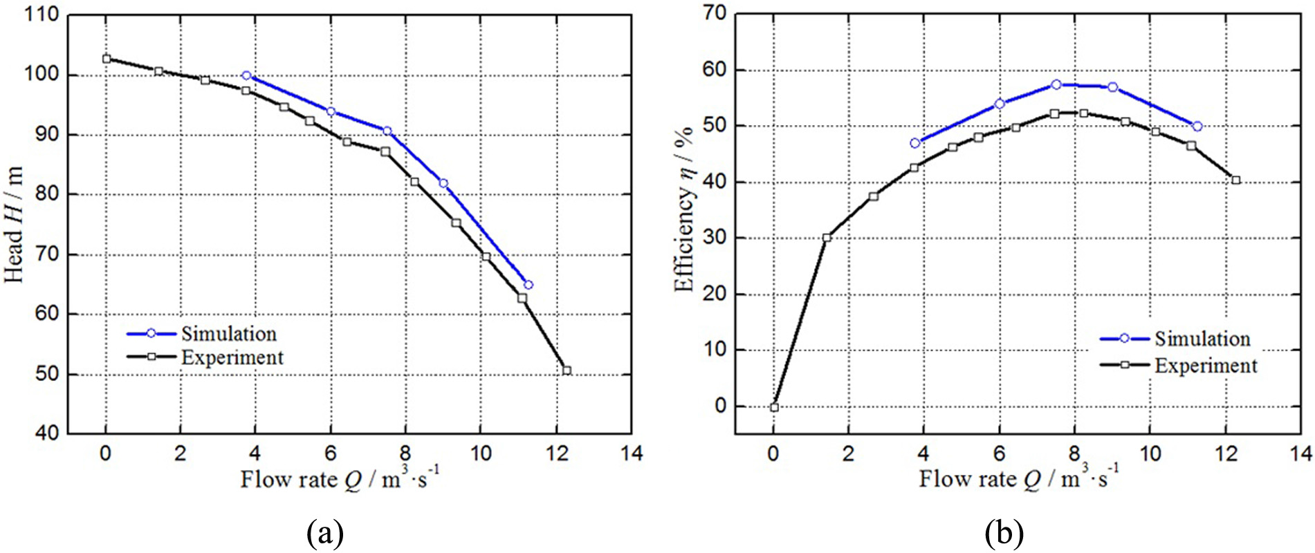
Comparison of experimental and numerical results.
Results and discussions
Pump performance characteristics
To add splitter blades was considered to be a technique to improve the pump performance characteristics by many researches.2–4 In this article, two complex impellers (impellers 2 and 3) were designed and taken as optimization models to compare with original impeller (impeller 1). Figure 5 emphasizes pump heads and operating efficiencies on the different values of flow rates (0.5QN, 0.8QN, QN, 1.2QN, and 1.5QN) for the pumps with impellers 1–3. Significantly, the pump performance was enhanced by using splitter blades. The heads of pump 2 have increased 10 m approximately on the operational conditions by comparing with pump 1, while the efficiencies also have raised nearly 4%. These results favor the positive effect of splitter blade on the performance characteristics of the high-speed centrifugal pump. However, there is little difference between pump 2 and pump 3 for the head and operating efficiency according to Figure 5. The splitter-blade inlet diameter ds of pump 2 is 0.07 m and the radial length of splitter blade is 0.03 m, while the radial length of splitter blade of pump 3 is 0.05 m and obviously longer than that of pump 2. That is, to increase the length of splitter blade is not so effective on the pump performance. Especially, for the condition of QN, the head of pump 2 is 10 m higher than pump 1 and slightly higher than pump 3, while the efficiency of pump 2 is 3% higher than pump 1 (Figure 6).

Performance characteristics for three pumps: (a) pump head and (b) operating efficiency.

Performance characteristics under the condition of QN: (a) pump head and (b) operating efficiency.
Flow characteristics
In this section, the numerical simulations of the flow inside three pumps were carried out at the common flow rate of QN. Figure 7 shows the velocity vector fields in the blade passages of three pumps. Obvious flow separations were observed in the middle of the blade passage of impeller 1, and the jet-wake structure also exists in the impeller outlet flow. The rotating speed of the impeller is too high to result in the stall flow which causes some unsteady flows such as vortex flow and flow separation. For the jet-wake structure, the jet should be the main flow, 10 but just a small amount in the outlet flow of impeller 1 because of the high speed of the rotating impeller. The wake belongs to the following flow and has the different flowing direction with the main flow, which seriously affects the outflow quality to induce the unsteady impeller–volute interaction. The splitter blades significantly improve the unsteady flow in the blade passage according to the exhibition in the impellers 2 and 3. The flow separations are diminished while the jetting flow increases. Comparing with the normal-speed rotating impeller, the positive effect of the splitter blade is more distinct for the high-speed centrifugal pump. Meanwhile, the fluid concentrates on flowing through the area between the suction surface of splitter blade and the pressure surface of long blade. That means that the splitter blade should be designed with a bias to the suction surface of long blade to increase the effective flow area. Also, the inflow incident angle of the splitter blade should be tangent to the blade leading edge and reduce the flow-impact loss.

Velocity vectors in the blade passage.
The turbulent flow in the pump was studied by simulating the turbulence kinetic energy distribution, as shown in Figure 8. Large turbulence kinetic energy is observed at the area between the blade and laryngeal of the volute. For three pumps, all the high gradients of turbulence kinetic energy in the flow field concentrate in the pressure surface of blade. The splitter blade obviously makes the turbulence kinetic energy distribution harmony and decreases the dissipation of turbulent kinetic energy. The impeller rotates with respect to the volute casing, and this relative movement generates the unsteady interaction which induces the flow instabilities such as pressure fluctuations.

Turbulence kinetic energy for different pumps.
A time-dependent non-dimensional pressure coefficient C was defined as follows


Pressure contours for different pumps.
Periodic pressure variations
The quantitative analyses are hard to be conducted according to the numerical simulations of the pressure fields in pumps, so several monitoring points were arranged in the flow channel of the interface between the impeller and the volute for studying the effects of the splitter blade on pressure fluctuations. Figure 10 shows the positions of monitoring points recording the pressure variations. Eight points were located in a circle with the diameter of 0.105 m which is the median between the impeller outlet diameter and the base volute diameter. These points were evenly distributed in the base circle and the monitor 1 was arranged at the position to the volute tongue.

Monitoring point locations.
The monitored pressure in one full cycle of the impeller rotation experiences a periodical variation such as the recorded data of monitors 3 and 5 in Figure 11. On the flow rates of QN, there are similar periodic pressure variations for the different monitors. However, the fluctuating amplitudes are observed to be obviously different, as shown in Figure 12. The pressure amplitude of monitor 3 is maximum while that of monitor 5 is minimum, so the recorded data of monitor 3 were taken as the theoretical foundation to explore the effects of the splitter blade.
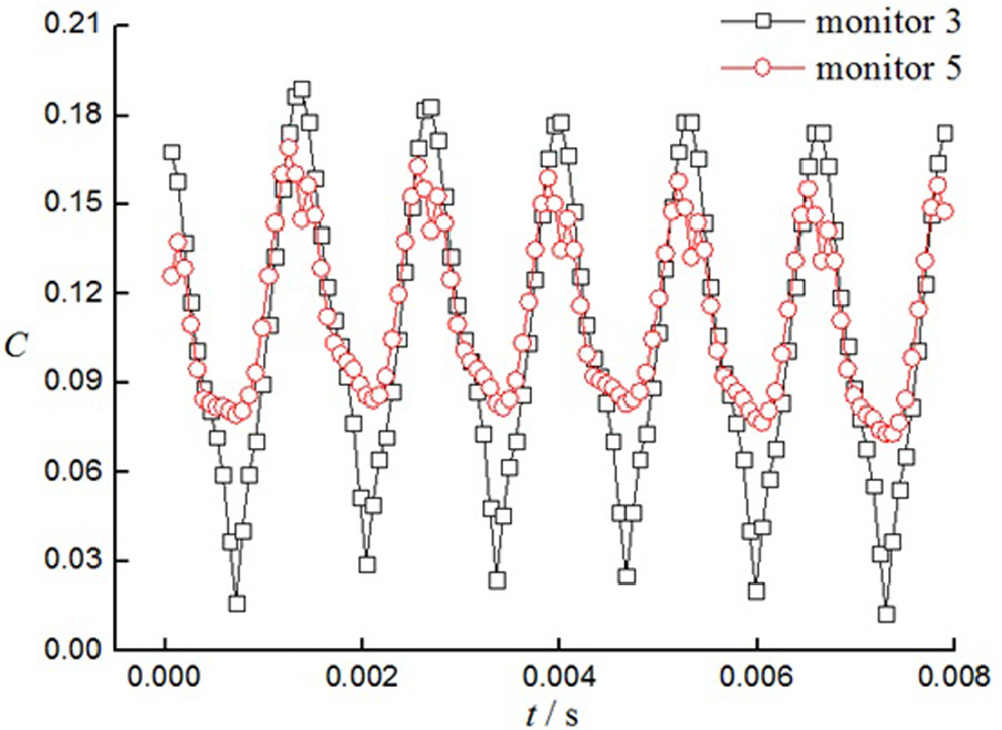
Monitored pressure variations.

Fluctuating pressure amplitudes of monitor points.
Figure 13 shows the recorded pressure fluctuations of monitor 3 in the three pumps on the flow rates of 0.8QN, QN, and 1.2QN by the time-domain analysis method. The pressure amplitude in pump 1 is obviously higher than that in other pumps, but there are less differences in the pressure variations between pump 2 and pump 3. The splitter blade plays a positive role in improving the unsteady flow in the high-speed centrifugal pump according to the significant decrease in the fluctuating pressure amplitude. The amplitude of impeller 2 is just one-third of that of impeller 1 as shown in Figure 14. Noteworthily, the amplitude of impeller 2 is very close with that of impeller 3, that is, to lengthen the splitter blade does not influence the pressure field much.

Pressure variations in time domain.

Pressure amplitudes in three pumps.
Moreover, the frequency domain analyses for the fluctuating pressure variations in three pumps were also performed. The frequency domain results were transformed from the time domain results by fast Fourier transform (FFT) method. The shaft rotating frequency (fS) was used in this article and was 126 Hz according to the impeller rotating speed of 7600 r/min. The impeller blade passing frequency (fBPF) is another important parameter for the centrifugal pump and is 756 Hz because of the impeller number of 6. Figure 15 shows that the maximum pressure amplitude occurs on the frequency of fBPF, while other pressure fluctuations appear on the multiples of fBPF for three pumps. Adding splitter blades has positive effect on deceasing the maximum pressure amplitude and other pressure fluctuations on the frequencies of the multiple of the sum of the long-blade number plus the splitter-blade number. This activity makes uniform the pressure fluctuations and favors the steady flow in the pump.

Pressure spectrums in the three pumps.
Conclusion
In this article, the effects of the splitter blade on the pump performance characteristics of a high-speed centrifugal pump were studied by the numerical simulations. The simulation method was validated by conducting the performance tests on the full work conditions for the model pump. To add the splitter blades in the impeller is in favor of the pump performance characteristics. The pump head was increased 10 m approximately, while the operating efficiency was raised nearly 4%, but the increase in the splitter-blade length has less effects on the pump performance. As for the flow characteristics, the jet-wake structure in the outflow from the impeller was obviously improved by the splitter blade. The jetting flow increases greatly and the flow separations in the blade passage are diminished. Noteworthily, the splitter blade should be designed to locate with a bias to the suction surface of the long blade for increasing the effective flow area. Moreover, the splitter blade obviously makes the turbulence kinetic energy distribution harmony and decreases the dissipation of turbulent kinetic energy to improve the flow stability. Periodic pressure fluctuations were observed in the flow field of the pump by the recorded data of monitor points. The maximum pressure amplitude was significantly decreased using the splitter blades, but the length of the splitter blade had not affected the pressure field much. Meanwhile, the pressure fluctuations in the frequency domain were more evenly distributed in the complex impeller, which enhanced the steady flow in the pump.
Footnotes
Handling Editor: Hyung Hee Cho
Declaration of conflicting interests
The author(s) declared no potential conflicts of interest with respect to the research, authorship, and/or publication of this article.
Funding
The author(s) disclosed receipt of the following financial support for the research, authorship, and/or publication of this article: This research is sponsored by the State Key Program of National Natural Science of China (Grant No. 51239005).