
Abstract
Many servo systems require micro/nano-level positioning accuracy. This requirement sets a number of challenges from the viewpoint of sensing, actuation, and control algorithms. This article considers control algorithms for precision positioning. We examine how prior knowledge about the parameterization of control structure and the disturbance spectrum should be utilized in the design of control algorithms. An outer-loop inverse-based Youla–Kucera parameterization is built in the article. The presented algorithms are evaluated on a tutorial example of a galvo scanner system.
Keywords
Introduction
A precision servo system aims at accurately positioning the controlled object(s) to follow the desired trajectories. The controlled object here, for instance, can be a read/write head for accessing data in a commercial hard disk drive (HDD), 1 a stage for carrying wafers (called wafer stage) in semiconductor lithography, 2 or a galvo scanner for deflecting a laser beam in selective laser sintering (SLS) additive manufacturing. 3 In all examples, the required position accuracies are quite high. In the HDD example, the scenario can be mimicked by an airplane flying at 5,000,000 mile/h above a 100,000-lane highway to follow the center of a lane whose width is only a fraction of an inch! 4 Such ultra-high precision is achieved by careful consideration of various disciplines in mechanical engineering. From the viewpoint of system integration, the design elements can be classified to the following four categories:
Hardware and sensing components, such as fluid or air bearings for reduced friction, laser interferometers or high-precision encoders for accurate measurements, and piezo-electronic actuators for fine positioning;
Operation environment, including, for example, friction-isolation tables, clean room, and thermostatic chambers;
Task plans and arrangements, such as well-designed trajectories, repetitive tasks in a manufacturing process, and so on;
Servo control algorithms, such as adaptive control, repetitive control (RC), predictive control, and optimal control.
A well-designed precision system needs optimized considerations in all the above categories. Servo control, as the final step, is responsible for compensating as much as possible the imperfections from the previous three design processes. Such imperfections include (1) hardware imperfection, such as system resonances, delays in motor drivers, and delays in signal acquisition; (2) environmental disturbance, such as turbulent airflow, periodic disturbance from cooling fans in HDD, and structural coupling between mirrors in the galvo scanner; and (3) special errors due to the task nature, such as repeated trajectories in the wafer scanner.
Errors from the above sources present great challenges in reaching position accuracies at the micro/nano-scale. Fortunately, part of them—for example, imperfect motor rotation, repeated trajectories, and fan noises—are repeatable once the hardware and the trajectory are fixed. Other errors—such as environmental vibrations—may vary case by case; they are, however, at least structured and can be compensated by carefully designed servo controllers.
In this tutorial, the loop shaping of the feedback control in precision positioning systems is considered. In the presence of various aforementioned error sources, the feedback loop needs to have the flexibility of providing different closed-loop features for error reduction and guarantee the stability under different loop modifications. To satisfy this requirement, enhanced control at selected frequencies has been adopted by many researchers. Based on the location of servo enhancement, enhanced control can be categorized into three groups to deal with (1) independent disturbance frequencies by, for instance, peak filters,5,6 adaptive feedforward cancellation,7,8 disturbance observers,9–11 and Youla–Kucera (YK) parameterization;12–15 (2) a fundamental frequency and its integer multiples by means of RC and its variants;16,17and (3) broadband frequencies through adaptive disturbance rejection, 18 adaptive noise cancellation, 19 and so on. This article discusses recent results in enhanced control to reach the desired servo goals.
A preliminary version of this study was presented in the 2013 American Control Conference. 20 This article extends the contents by proposing a new outer-loop inverse-based YK parameterization and presenting a detailed case study on the galvo scanner system. The case study is aimed to validate the proposed control algorithm and illustrate how to apply them in practice. The main contributions of the article are:
Building flexible feedback loop-shaping schemes to compensate various error sources in precision positioning;
Formulating a new outer-loop inverse-based YK parameterization;
Presenting a detailed case study on the galvo scanner system to validate the proposed control algorithm.
The remainder of the article will unfold and discuss several feedback control algorithms including add-on designs for precision positioning. Section “Feedback controller parameterization” reviews some fundamental feedback controller parameterizations. From there, section “Proposed controller factorization” discusses the proposed controller factorizations, that is, inverse-based YK parameterization and its variant. A case study is conducted on a galvo scanner control in section “A case study on a galvo scanner system,” and several comments on feedforward designs are provided in section “Remarks.” Section “Conclusion” concludes the article.
Feedback controller parameterization
This section briefly reviews several fundamental concepts in feedback control and introduces YK parameterization for flexible servo designs.
A precision positioning system is designed to have an accurate plant dynamics P which is usually linear and time-invariant. For a single-input single-output plant controlled by linear controllers (at least at the steady state), the position servo design can essentially be cast as a loop-shaping problem. Consider the block diagram of a standard feedback design in Figure 1. The closed-loop transfer function from the disturbance

A standard closed-loop system under feedback control. 21

Magnitude response of the sensitivity function in section “Experimentation.”
The bandwidth in Figure 2 cannot be pushed to be arbitrarily large. From the practical perspective, a mechanical system cannot respond to arbitrarily fast control inputs due to hardware (such as motors and gears) limitations. It is common practice to keep the gain of the controller small at high frequencies. From the theoretical perspective, under mild conditions (for continuous-time systems, the relative degree of the loop transfer function
Well formulated tools such as proportional–integral–derivative (PID), lead-lag, and
A foundational tool suitable for achieving the design goal is the YK parameterization,14,15 also known as all-stabilizing controller parameterization. If a plant

Here, a pair
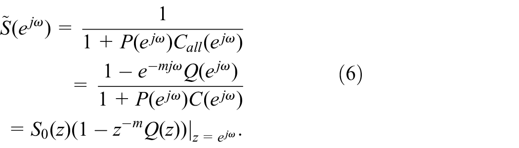
The sensitivity function with controller (1) in the loop is

which is affine in Q. Therefore, changing Q can directly shape
For stable P and C, one can simply choose


The remaining design task about choosing Q in equation (4) depends on the plant P and the desired closed-loop response. For example, candidate Q-filter designs can be found using a linear combination of some basis transfer functions (e.g.,
A forward-model YK parameterization.
Proposed controller factorization
Instead of a direct inversion of P by Q, this section discusses an alternative scheme that brings additional simplifications to equation (4). Although a general analysis can be made, we focus on precision servo systems and assume that the baseline controller C is stable.
Consider designing inverse-based YK parameterization in two steps: first, to perform a stable model inversion

A discrete-time inverse-based YK parameterization.
The transfer function of the overall feedback controller in Figure 4 is
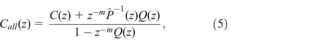
where high-gain control (increased control effort) is directly provided by
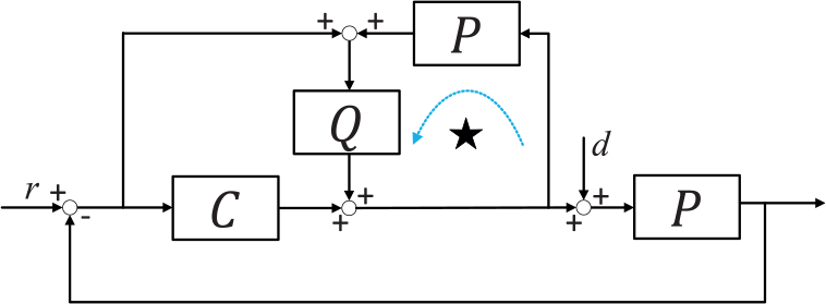
In some practices, when the plant and built-in controller (e.g., designed by manufacturers in the factory) are lumped together, only signals v and y in Figure 5 are accessible and separating the plant model


An outer-loop block diagram.

An outer-loop inverse-based YK parameterization.
Nominal stability of the closed-loop system can be guaranteed given proper coprime factorizations. Summarizing the requirements in each of the four introduced YK schemes yields Table 1.
Nominal stability conditions for the four add-on designs.

YK: Youla–Kucera.
When there is (stable and bounded) model uncertainty
Nominal stability condition in Table 1 is satisfied, that is, the closed loop is stable when
Robust stability requirement is met: for any
Remark 1
The above robust stability requirement is not difficult to satisfy. Take the inverse-based YK parameterization in equation (6) as an example, where

If
In equations (6) and (8), the add-on design narrows down to the design of
Low-frequency servo enhancement
An intuitive choice for
Narrow-band disturbance rejection
Vibrations are frequency-dependent signals by nature. Since the closed-loop bandwidth cannot be arbitrarily increased, vibrations at frequencies above the servo bandwidth are fundamentally more difficult to handle. Actually, such band-limited disturbances, if strong enough, significantly limit the servo performance. To compensate for such vibrations, some special feedback adjustments are needed. Meantime, we commonly want to keep as much as possible the original loop shape because it is often achieved after careful baseline design. A candidate add-on design is to use the proposed inverse-based YK parameterization and design a notch shape for

A Q design example for narrow-band disturbance rejection.
An example about disturbance attenuation in a HDD benchmark problem
22
is presented in Figure 8. This benchmark has been used in a number of publications on information storage systems. The compensation scheme is implemented for rejecting two strong vibrations at around 1100 and 1500 Hz. Both vibrations occur at frequencies above the baseline servo bandwidth (1060 Hz) and cannot be attenuated in the standard feedback setting. After compensation, the two originally sharp spectral peaks are actually visually not detectable due to the deep notch shape of

Frequency spectra of the position error signals in a simulated HDD benchmark: 1 TP (track pitch) = 254 nm in this example.
Take the example of
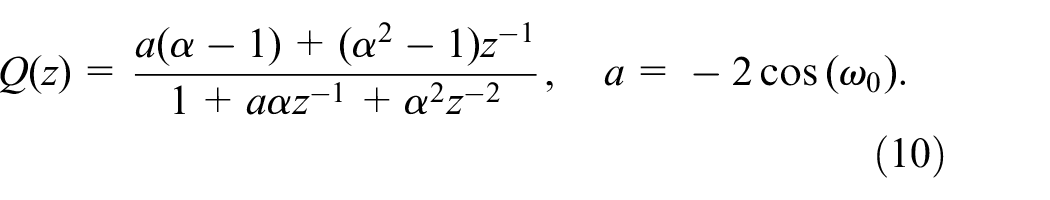
Extending equation (10), if multiple notches are desired, with

Here,
When
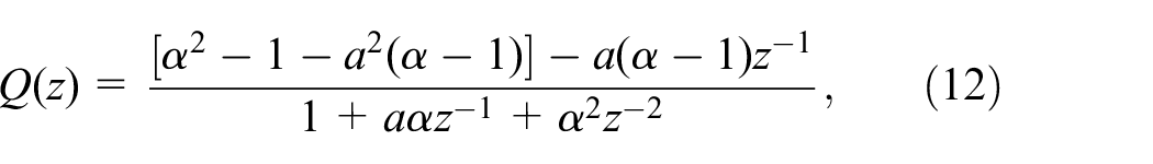
where
Repetitive control
An example application of RC is for addressing the problem involved in wafer-scanning process, one key step for circuit fabrication in the semiconductor industry. To print the circuit, the wafer is exposed to patterned ultraviolet lights that come through a mask carried by a reticle stage. The wafer stage and the reticle stage move the wafer and the mask in a synchronized manner. Due to the limited size of the lens, only a small part of the wafer is exposed at each scan, and the wafer is moved from one field to another between the scans. The scanning process is repeated until all required areas on the wafer have been exposed under the light. An intuition about RC is that if the same type of disturbance occurs after a fixed period of time, that is,
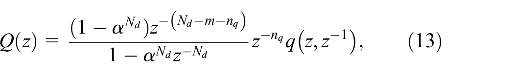
where

A Q design example for repetitive control.
Theorem 1
When
Figure 10 shows the experimental result of the algorithm to reduce the errors represented by the dashed line. With the repetitive learning control, the errors are observed to have reduced by two orders of magnitude compared to the case without compensation.

Tracking errors with the Q-filter configuration in equation (13).
General band-limited vibration compensation
The loop shaping in section “Narrow-band disturbance rejection” is for narrow-band disturbance rejection. When excitation sources are rich in frequency, a wider attenuation bandwidth of

The control of attenuation efforts by means of gain scheduling on Q.
A case study on a galvo scanner system
In this section, we provide the design and analysis steps for implementing the (outer-loop) inverse-based YK parameterization on a galvo scanner platform to verify the effectiveness of the proposed servo design.
As an important subcategory of additive manufacturing, SLS can directly fabricate metallic parts from digital models. In SLS, laser beams are controlled to melt the powder materials following pre-designed trajectories. Rather than moving the laser source, SLS efficiently applies a galvo scanner platform to reflect the laser beams. Besides SLS, the galvo scanner platform is also widely used in other laser-related applications such as laser scanning, laser engraving, and laser welding.
A typical galvo scanner platform is composed of two sets of mirrors, galvanometers, and control systems, as shown in Figure 12. The galvanometer consists of motors to rotate the mirrors and encoders to feedback the mirror position information. The mirror assembly is attached to the end of the motors in a coaxial manner and deflects the laser beam over the angular range of the motor shaft, as shown in Figure 13.

Schematic of hardware platform.
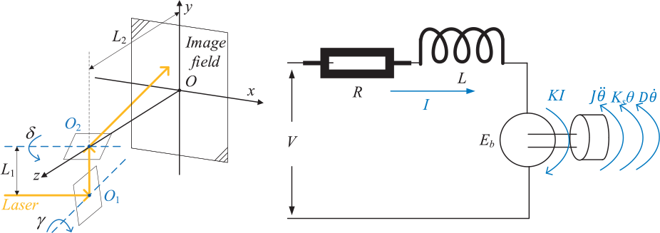
Schematic diagram and electrical model of galvo scanner.
Plant identification, PID tuning, and discretization
In the electrical model (Figure 13) of a generalized galvo scanner platform, the open-loop transfer function26,27 relating the input drive current
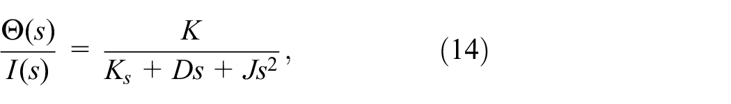
where K is the torque constant,

where

With

where the term

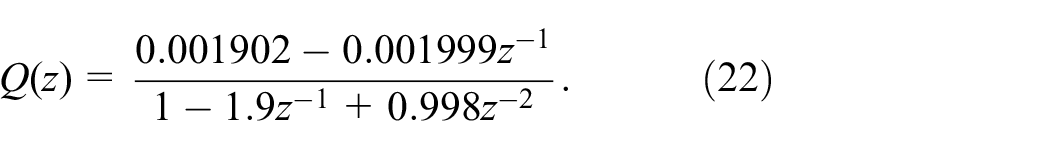
To implement the discrete-time YK scheme, the continuous-time plant and controller are, respectively, discretized by means of the zero-order-hold (ZOH) discretization and the bilinear transformation


The transfer function of the discrete-time plant with the sampling time

YK parameterization implementation
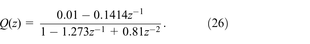
The inverse-based YK parameterization (Figure 4 and equation (5)) is applied to reject disturbances in the galvo scanner platform, such as channel crosstalk, atmospheric turbulence, and environmental vibration. Such disturbances are narrow-band by nature. For demonstration, a proof-of-concept single-frequency disturbance
As shown in Figure 14, by applying high-gain control of equation (5), a notch shape is introduced for

Magnitude responses of
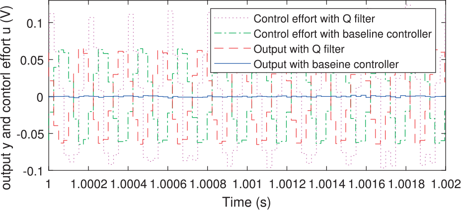
In regulation control, the
Figure 15 shows the simulated outputs and control efforts with the Q-filter and the baseline PID controller. The results verify that compared with the baseline controller, the inverse-based YK scheme can fully reject the disturbance at

Outputs and control efforts of the baseline controller and Q-filter.
Experimentation
Experiments are conducted on the galvo scanner platform
3
in Figure 12. During implementation, nonlinearity effects such as slew rate limit and input saturation are insignificant compared with the external disturbance and are thus omitted. A dSPACE DS1104 board connects designs in MATLAB with the servo drivers. The control signal is limited to ±10 V. The system is subjected to broadband random disturbances at a magnitude of about 10 mV. The sampling time
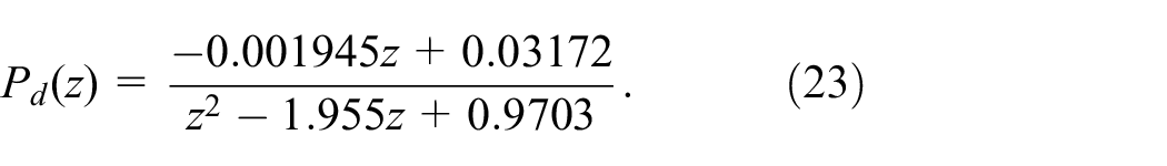
A pseudorandom binary sequence signal is used as an input to estimate the plant model. Magnitude responses of the measured and identified plants are shown in Figure 16. The identified plant model is expressed as

Magnitude response of the measured and identified plant.
One can observe that equations (21) and (23) share the same structure and similar poles with some gain normalization, which attests to the validity of the identified plant model.
Next, we take the galvo scanner and the servo drivers, namely, the lumped plant and controller, as the new augmented plant

Moving the unstable zero of
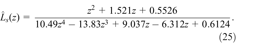
The magnitude responses of the measure system, the identified

Magnitude responses of the measured system, and identified
As shown in Figure 18, the control effort with the Q-filter is larger than that with the baseline controller. The disturbance is attenuated remarkably with the outer-loop inverse-based YK parameterization turned on. The performance gain is also clear in the frequency domain: in Figure 19, the spectral peak at 5 kHz is completely removed without visible amplification of disturbances at the other frequencies.
System outputs and control efforts with/without YK parameterization.

Spectrum of output
Remarks
The plant model and its inverse
The (inverse) model information is essential in the discussed control schemes since it not only provides convenience for feedback design but also is beneficial for tasks such as fault detection and disturbance isolation. Such a model is usually available in industries. By the physical construction, the input to actuators in a precision positioning system is usually a voltage/current signal that is approximately linear with respect to motor torque, and the measurement is commonly an angular or linear position. The inverse system dynamics thus usually has a double-differentiator type of frequency response due to Newton’s law. It is thus not difficult to obtain a stable nominal
Robust stability
Strictly speaking, after
Feedforward control
The feedback perspective for precision servo has been discussed. Due to space limit, detailed feedforward discussions are not included in this tutorial article. Necessity of feedforward control comes from the simple fact that feedback designs have bandwidth limitations. In the feedforward class of control algorithms, model-based design is also of essential importance. Inverse complementary sensitivity and inverse plant dynamics are two common approaches for feedforward design. When the process is repetitive, iterative learning control (ILC) is another powerful tool for error correction in the iteration domain.
Adaptive configuration
When the disturbance spectra is not known (but with known structure), adaptive control can be applied to update the parameters of
Reference of YK parameterization
For additional materials about YK parameterization, readers can refer to the literature.12,21,30 In the discrete-time case, the simplest example of Q design is using
Conclusion
In this article, the control methodologies for precision positioning systems have been studied. The central concept is that flexible loop shaping is a convenient tool for addressing various servo problems. Multiple simulation and experimental results on actual engineering problems are used to validate the presented designs. Besides the examples used in this article, the control structure has also been tested under other systems, such as electrical power steering in automotive vehicles 24 and active suspension systems.11,12
Footnotes
Appendix 1
Handling Editor: Yong Chen
Declaration of conflicting interests
The author(s) declared no potential conflicts of interest with respect to the research, authorship, and/or publication of this article.
Funding
The author(s) received no financial support for the research, authorship, and/or publication of this article.