
Abstract
This article develops a long-stroke nano-positioning stage and discusses the impacts of sensor layouts on the positioning performance. The stage consists of a piezoelectric-transducer stage and a motor stage. First, we obtain the transfer functions of the two stages by experiments and design robust loop-shaping controllers to improve their performance. Second, we integrate the two stages and designed two sensor layouts, a local sensor layout using encoders and a global sensor layout using laser interferometers, to achieve precision positioning for large travels. Finally, we implement the designed controllers and sensor layouts for experimental verification. Based on the results, the proposed combined stage is deemed effective in accomplishing nano-positioning for long displacements. In addition, the local sensor layout can achieve high precision but with global misalignments, while the global sensor layout can eliminate the global misalignments but suffer large sensor noises. Therefore, we further constructed a modified sensor layout that can combine the merits and achieve precision positioning with a root-mean-square error of 5 nm and a misalignment error of 16 nm for a 10-cm travel.
Introduction
Precision positioning control is increasingly important as technologies advance. For example, Gan et al. 1 used a linear switched reluctance motor with H-infinity loop-shaping design to reach a steady-state error (SSE) of 3.5 µm. Park 2 constructed a 3 degree-of-freedom hybrid stage by three linear motors and four voice coil motors and applied proportional–integral control to acquire travels up to 300 mm and a minimum resolution of 10 nm. Chen et al. 3 approximated electromagnetic nonlinearity by cubic polynomials and proposed adaptive robust control to achieve tracking performance for industrial applications. Yao et al. 4 applied a robust integral with adaptive control to a hydraulic rotary actuator and verified the high-accuracy tracking performance by experiment. Piezoelectric transducer (lead zirconate titanate (PZT)) actuators are frequently considered in precision positioning because of high-driven forces and fast responses. However, PZT nonlinearities, such as hysteresis and creep, might degrade system performance. Therefore, several nonlinear models were proposed, including the Bouc-Wen model,5,6 the Preisach model,7,8 and the Prandtl-Ishlinskii inverse model.9,10 Liu et al. 11 identified the hysteresis and creep dynamics of piezoelectric actuators and applied model-inversion control to get an error of less than 4.32% at 600 Hz. Many advanced controls have been applied to improve the performance of PZT stages. For example, Kenton and Leang 12 applied repetitive control to achieve a root-mean-square error (RMSE) of 0.6% at 100 Hz. Helfrich et al. 13 combined iterative learning control and robust control to obtain an RMSE of less than 40 nm on three axes. Wang et al. 14 applied robust loop-shaping techniques to PZT to achieve an RMSE of 5.4 nm for a travel of 1000 nm. Other robust control techniques can also be considered. For instance, Sun et al. 15 applied finite frequency H∞ control and constrained adaptive robust control technology 16 to vehicle active suspension systems. Yao et al. 17 proposed output feedback nonlinear robust control with an extended state observer to a hydraulic system.
Because the working ranges of PZTs are limited, many studies tried to extend their travel ranges. For instance, Chu and Fan 18 designed mechanisms for a PZT stage to achieve a maximum stroke of 10 mm with an error of less than 50 nm. Peng et al. 19 applied adaptive sliding mode control to PZT and electromagnetic actuators and reached a positioning field of 1 mm2 with an RMSE of 30 nm. Wu et al. 20 built a one-axial combined stage and obtained an RMSE of 5 nm with a working range of 50 mm. This article extends these ideas to integrate a two-axial PZT stage with a motor stage for achieving nano-positioning over long travels and further investigates the influences of displacement measurements on stage performance. The frequently used measuring instruments include linear variable differential transformers, encoders, capacitive sensors, charge sensors, and laser interferometers. 21 The former four sensors detect local displacements while the last one provides global positions. However, there has been no profound discussion on how different sensor layouts might influence the positioning performance of precision stages. Therefore, in this article, we apply encoders and interferometers to build a local sensor layout and a global sensor layout, respectively, and discuss the pros and cons of these layouts based on experimental results.
This article is organized as follows: section “System description and identification” describes the PZT and motor stages and derives their dynamic models by experiments; section “Controller design and implementation” designs and implements robust loop-shaping controllers for the stages and demonstrates the experimental responses; section “Stage integration and control by different sensor layouts” integrates the two stages for nano-positioning during long travels and develops two sensor layouts for performance comparison. The results indicate that the local sensor layout can achieve better precision but suffers global misalignments, while the global sensor layout can eliminate the global misalignments but endures larger noises. Therefore, we further build a modified sensor layout to combine the advantages of the aforementioned two layouts and to achieve an RMSE of about 5 nm and a misalignment error of about 16 nm for a 10-cm travel. Finally, we draw conclusions in section “Concluding remarks.”
System description and identification
The combined stage consists of a PZT stage and a motor stage, as shown in Figure 1(a). The PZT stage was driven by two PZTs to manipulate 15 µm × 15 µm stokes on two axes and was equipped with linear encoders with a resolution of 1.22 nm on both axes for measuring local displacements. The motor stage was steered by two stepper motors to provide 100 mm × 100 mm displacements on two axes and was equipped with two encoders with a resolution of 0.1 µm for measurement and control. Therefore, we can integrate the PZT (see Figure 1(b)) and the motor stages (see Figure 1(c)) to accomplish precision positioning over long travels. In addition, we applied laser interferometers (see Figure 1(d)) to measure the global displacements of the combined stage. The specifications of the equipment are illustrated in Table 1. The control structure is shown in Figure 1(e), where we applied the data-acquisition (DAQ) cards to receive signals from the PZT stage and stepper motors. The control inputs were calculated by the computer with the software of Visual Studio 2010 C++ and transmitted to the stages through the DAQ cards.

The proposed system: (a) the combined stage, (b) the PZT stage, (c) the motor stage, (d) the laser interferometer, and (e) the control structure.
Specifications of the experimental instruments.
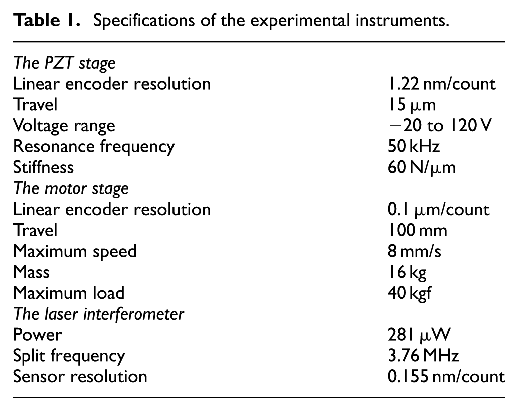
Figure 2 illustrates the hardware layouts of the combined stage. We used two DAQ boards, PCIe-6323 and PCI-6221, to control the stepper motors by pulse-width modulation signals and to feedback the encoder signals. In addition, we applied DAQ PCI-6229 to transmit the control signals and encoder signals of the PZT stage. Furthermore, the PZT control signals were amplified 10 times by the Amplifier E-663 to drive the PZTs. Finally, the global stage positions were recorded by an axis laser board N1231B.

Hardware layouts of the combined stage.
Identification of the PZT stage
The models of the PZT stage were derived by experiments. First, we applied a swept sinusoidal signal,

for

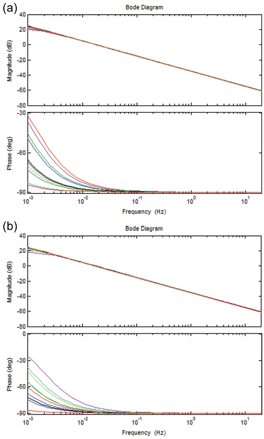
Bode plots of the PZT stage: (a)
Identification of the motor stage
Similarly, for the motor stage, we applied a swept sinusoidal input signal,

for
Bode plots of the motor stage: (a) bode plots of
Controller design and implementation
This section demonstrates the design and implementation of robust controllers for the PZT and motor stages and compared the simulation and experimental results.
Controller design for the PZT stage
From Figure 3, we can note the variation of the PZT models. Therefore, we can regard the systems as linear transfer functions with uncertainties and disturbances and apply robust control techniques to improve system performance while guaranteeing stability. Assume a nominal plant

where
Therefore, we can select the nominal plants

The gaps of the identified PZT models are illustrated in Appendix 1, where the nominal plants are selected as in the following
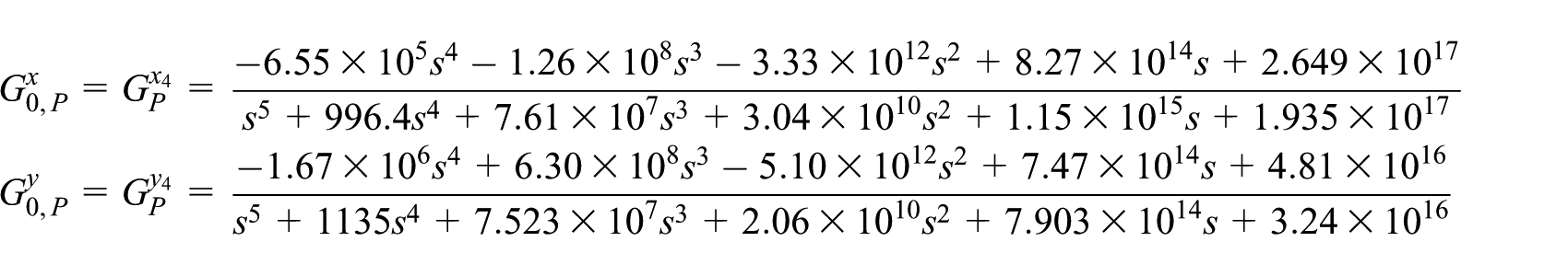
which gives
A closed-loop system with a perturbed plant
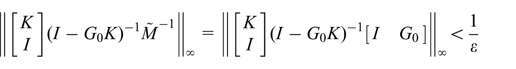
Hence, we can further define the system’s stability margin
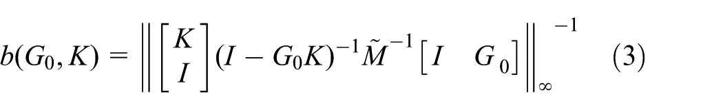
so that the closed-loop system is internally stable for all uncertainties with

Robust stability analysis: (a) the original closed-loop system and (b) rearrangement.
We applied H∞ loop-shaping techniques, 12 as shown in Figure 6(a), to improve the system performance. The weighting functions for the PZT stage were adjusted by experiments and selected as follows
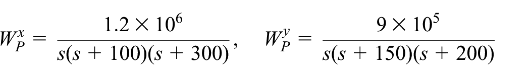

Loop-shaping design for the PZT stage: (a) loop-shaping technique, (b) bode plot for x-axis, and (c) bode plot for y-axis.
The Bode plots of the original plant
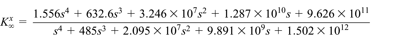

which gave a stability margin of
We implemented the weighted controllers,


where e indicates the error between the input command and the output response, and T is the final time in simulation or experiments. It is noted from Table 2 that the theoretical errors (SSE, RMSE, and MAE) were zero while the experimental errors were small but not exactly zero because of system disturbances and sensor noises. Based on these comparisons, the designed robust controllers can provide satisfactory responses.

Step responses of the PZT stage: (a) 1 µm x-axis and (b) 5 µm y-axis.
Response analyses of the PZT stage.
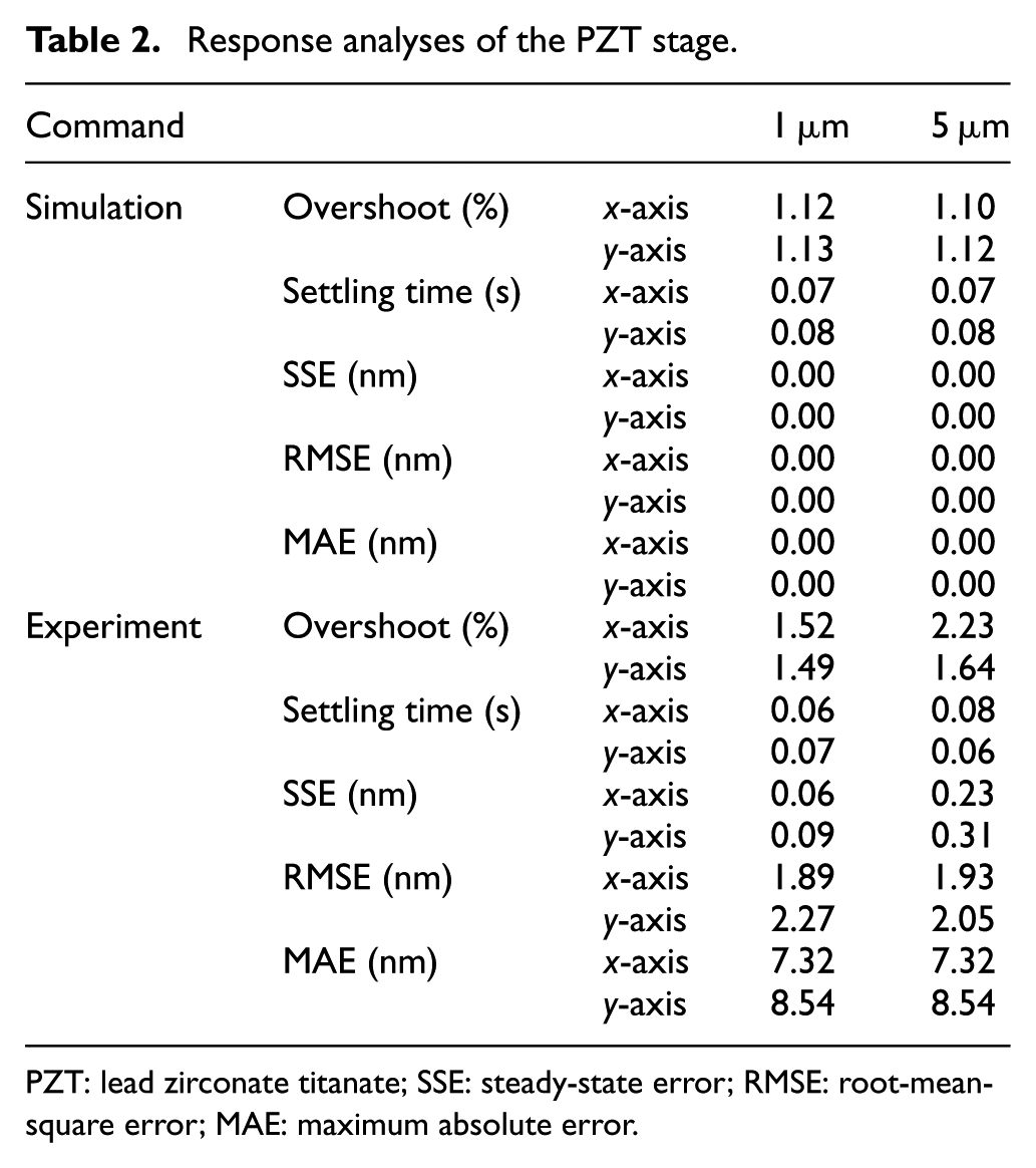
PZT: lead zirconate titanate; SSE: steady-state error; RMSE: root-mean-square error; MAE: maximum absolute error.
Controller design for the motor stage
For the motor stage, we considered the models of Figure 4 and illustrated their gaps in Appendix 1. Similarly, we applied (2) to select the nominal plants
We further noted that the Bode plots of Figure 4 can be approximated by an integral. Therefore, we can simplify the control design by directly deriving the mathematical model of the motor stage. The stepper motor is controlled by pulse signals and makes one complete revolution with 20,000 pulses, while the pitch of the screw is 2 mm/rev. In other words, given an input signal of

We calculated the gaps between
Applying the loop-shaping design, we adjusted and selected the following weighting function

to increase the system gain at the low-frequency range to suppress disturbances. Because the mechanical friction of the motor stage can effectively isolate high-frequency disturbances and noises, we tried higher-order weightings to suppress the high-frequency gains but obtained similar results. Therefore, we can use the constant weighting to derive a lower-order H∞ controller that can simplify controller implementation. The robust controller using
which gave a stability margin of
We implemented the designed controller

Step responses of the motor stage: (a) 100 µm, (b) 1000 µm, (c) 10 mm, and (d) 100 mm.
Responses analyses of the motor stage.

SSE: steady-state error; RMSE: root-mean-square error; MAE: maximum absolute error.
Stage integration and control by different sensor layouts
We integrated the PZT and the motor stages, as shown in Figure 1(a), to achieve precision positioning for long travels. We applied encoders and interferometers to construct a local sensor layout (see Figure 9(a)) and a global sensor layout (see Figure 9(b)), respectively, and compared their impacts on positioning performance. The local sensor layout used four encoders to measure the local positions of the PZT stage,

as shown in Figure 9(c), so that the PZT stage was activated when the error

Control block diagram: (a) the local sensor layout with four encoders, (b) the global sensor layout with two interferometers, and (c) the anti-locking function.
We further applied multi-thread control 20 for the PZT and the motor stages for synchronization because the sampling rates of the PZT and the motor stage were 5 and 1 kHz, respectively. If we used single-thread control with a unified sampling frequency for both PZT and motor stages, the PZT responses would be slowed down and the system performance degraded. Therefore, we controlled the two stages simultaneously with the following multi-thread control: the PZT and the motor stage was sampled and controlled five and one times, respectively, in 1 ms.
Stage control by the local sensor layout
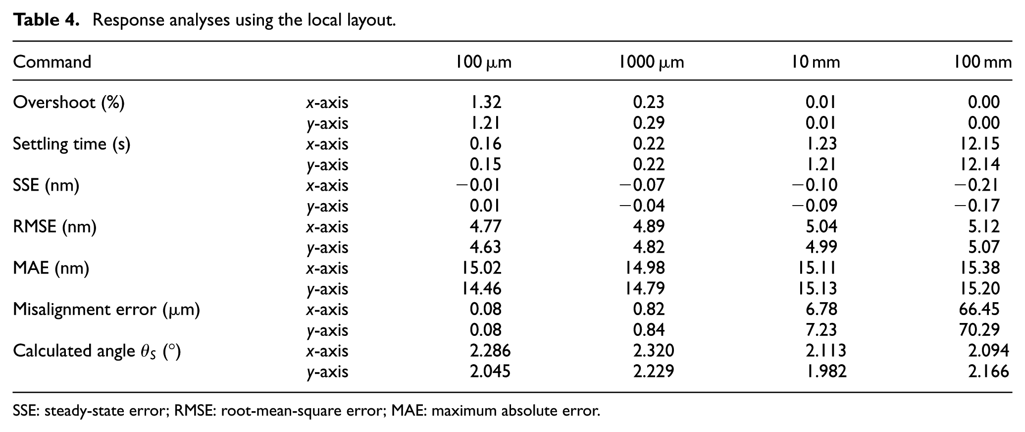
We first implemented the designed controllers with the local sensor layout to track step commands of 100 µm, 1000 µm, 10 mm, and 100 mm on both axes. The experimental results are shown in Figure 10(a) and (b) and Table 4. Note that Figure 10 only illustrates the x-axis responses because the y-axis responses are similar. First, the overshoots were about 1–3 µm for all experiments so that the percentage overshoots decreased as the displacements increased. Second, the settling time was slightly smaller than that of the motor stage (see Table 3) because the motor stage made long travels and the PZT stage provided faster responses at the final 5 µm travel by (8). Third, the SSEs were nearly zero because of the integral terms in the loop transfer functions, while the RMSEs and MAEs were about 5 and 15 nm, respectively, by the designed robust controllers. Finally, we compared the global positions measured by the interferometers and calculated the misalignment errors, which were caused by the inclined angles of the axes. As illustrated in Figure 10(c), when the encoders were not placed exactly on the same axis as the interferometers, the local sensor layout resulted in global positioning errors. We measured the global displacements

where T is the final time in experiments. As shown in Table 4, the misalignment errors were 80 nm, 820 nm, 6.78 µm, and 66.45 µm for the step commands of 100 µm, 1000 µm, 10 mm, and 100 mm, respectively. This resulted in about a 0.07% global positioning error and an inclined angle of

Combined stage control with the local sensor layout: (a) x-axis responses: 100 and 1000 µm, (b) x-axis responses: 10 and 100 mm, and (c) misalignment errors caused by sensor coordinates.
Response analyses using the local layout.
SSE: steady-state error; RMSE: root-mean-square error; MAE: maximum absolute error.
Stage control by the global sensor layout
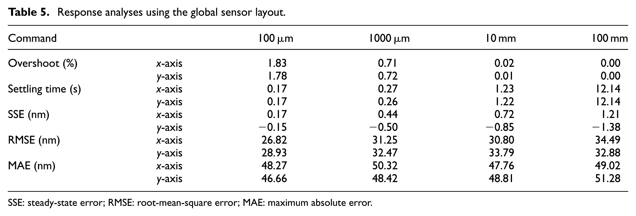
Similarly, we implemented the designed controllers with the global sensor layout to track step commands of 100 µm, 1000 µm, 10 mm, and 100 mm. The experimental results are illustrated in Figure 11 and Table 5. First, the percentage overshoots were less than 2% and decreased as the travels increased. Second, the settling time was smaller than that of the motor stage because both stages worked together to reach the final states. Finally, the SSEs were nearly zero because of the integral terms in the loop transfer functions. The errors (SSE, RMSE, and MAE), however, were much larger than those by the local sensor layout (see Table 4) because, though they can achieve global positioning, the interferometers suffered much greater noises than the encoders. That is, the local sensor layout can accomplish smaller RMSE and MAE but suffers misalignment errors. On the other hand, the global sensor layout can achieve global positioning but bears greater RMSE and MAE. Therefore, we need to consider a new layout to combine the merits of these two sensor layouts.

Step responses of the combined stage with the global sensor layout: (a) x-axis responses: 100 and 1000 µm and (b) x-axis responses: 10 and 100 mm.
Response analyses using the global sensor layout.
SSE: steady-state error; RMSE: root-mean-square error; MAE: maximum absolute error.
Modified sensor layout for the combined stage
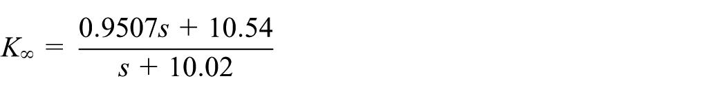
We constructed a modified control structure to combine the advantages of the local and global sensor layouts. The modified structure is shown in Figure 12(a), which is similar to the local sensor layout but with shaped input commands to eliminate the misalignment errors. In Figure 12(c), the global position can be seen as

where we adjusted the command and allowed the motor stage to travel a longer distance to compensate the misalignment errors. We set the inclined angle as

Effects of the modified sensor layout: (a) the modified sensor layout, (b) without input shaping, and (c) with input shaping.
Response analyses using the modified sensor layout.

SSE: steady-state error; RMSE: root-mean-square error; MAE: maximum absolute error.
Concluding remarks
This article has integrated a PZT stage and a motor stage to achieve long-stroke precision positioning and demonstrated the impacts of sensor layouts on system performance. First, we designed robust controllers to reach an RMSE of about 2 nm for the PZT stage and a travel of 10 cm for the motor stage. Second, we assembled the two stages and designed two sensor layouts to accomplish nano-positioning for long travels. Third, we discussed the pros and cons of the local and global sensor layouts: the local sensor layout acquired better precision but induced misalignment errors, while the global sensor layout eliminated the misalignment error but suffered larger sensor noises. Therefore, we further proposed a modified sensor structure that combined the merits of the local and global sensor layouts. The experimental results showed that the proposed stage and control can achieve an RMSE of about 5 nm and a misalignment error of about 16 nm for a 10-cm travel. In the future, we would like to apply the combined stage to micro-structure fabrication.
Footnotes
Appendix 1
Academic Editor: Jianyong Yao
Declaration of conflicting interests
The author(s) declared no potential conflicts of interest with respect to the research, authorship, and/or publication of this article.
Funding
The author(s) disclosed receipt of the following financial support for the research, authorship, and/or publication of this article: This work was financially supported, in part, by the Ministry of Science and Technology of Taiwan with Grants 98-2221-E-002-167-MY3 and 102-2221-E-002-150.