
Abstract
The analysis of medium- to high-frequency vibrations of structures is of particular interest in various fields, including the aviation and ship-building industries. Energy flow analysis is well known to be effective for structural acoustics problems in the medium- to high-frequency range, with sufficient detail to include all significant information of the vibrational energy levels or global variation in vibrational energy densities. The aim of this article is to develop energy flow models for a dilatational wave in three-dimensional elastic solids. The energy governing equation derived for the model is expressed in terms of the time- and space-averaged energy density, which represents the global variation of the energy density quite well. Numerical analyses are performed to verify the validity and accuracy of the model for a cube-shaped structure vibrating at a single frequency, and the results of the analysis of energy density distributions from the energy flow analysis that is developed are compared to those obtained using NASTRAN. The energy flow models for the elastic solids, which are useful in the prediction of the vibrational response for a three-dimensional structural analysis at a medium-to-high frequency, are newly derived.
Introduction
During the design phase, a vibrational analysis is implemented for built-up structures to predict the vibrational level of the structures and to identify structure-borne noise paths. Over the last few decades, advances in technology have drawn attention to high-frequency noise and vibration. Although finite element analysis (FEA) or boundary element analysis (BEA) is often used to predict vibrational response, FEA and BEA are difficult to apply for high-frequency vibrational analyses because the mesh size requirement is unreasonably small, resulting in a high computational intensity.
Various approaches have been attempted in order to overcome the limitations of conventional methods. For example, statistical energy analysis (SEA) is a representative method using statistical approaches, and it has been used to predict the space- and frequency-averaged response of the structure at high frequencies. However, SEA has some limitations in offering detailed information, such as the spatial variation of energy density or energy flow that are essential in the design of structures. As an alternative, energy flow analysis (EFA) was developed in order to predict the vibrational response of the structure. EFA formulates the flow of mechanical energy, which is analogous to heat conduction. Since the energy governing equation for EFA is in the form of a parabolic partial differential equation, the solution can suggest the spatial variation of energy densities or energy flow paths.
The EFA was first introduced by Belov et al. 1 Nefske and Sung 2 applied FEA to the energy governing equation in order to predict the vibrational response of the Euler–Bernoulli beam. Wohlever and Bernhard 3 established the energy flow model based on classical displacement solutions for a harmonically excited rod and Euler–Bernoulli beam. Bouthier and Bernhard4,5 also derived energy governing equations for the membrane and Kirchhoff plate. Cho 6 developed the joint relationships for coupled structures based on the concept of a power transmission and reflection coefficient. Park et al.7,8 developed energy flow models for the in-plane waves of isotropic thin plates, as well as a flexural wave in an orthotropic thin plate. Park and Hong9–11 developed the energy governing equations of the Timoshenko beam and Mindlin plate. Song and Hong 12 developed a non-conservative joint for the EFA of a coupled beam structure, and Song et al. 13 extended this model for penetration of beam-plate structures. Kwon et al. 14 derived the energy governing equation for the out-of-plane wave in a doubly curved shell with two curvatures along each orthogonal coordinate axes (Table 1).
Summary of related studies and comparison with this study.

In prior EFA, the energy governing equation was derived for a one-dimensional (1D) or two-dimensional (2D) structure, such as a beam, plate, membrane, and shell. However, there are many industrial situations in vibration analysis where it is necessary to determine the three-dimensional (3D) vibrational response, such as in the pier of a bridge, core of an industrial generator, or in an automotive frame. Usually, these structures can be analyzed by modeling with a solid element based on finite element method (FEM) at low frequencies. Even then, it is impossible to apply these to the vibrational problem at a medium-to-high frequency. Since the precise vibrational analysis for 3D structure vibrating at a medium-to-high frequency is required, the development of an energy flow model for a 3D structure is highly desirable.
In 3D elastic solids, structural waves can be composed of compressional waves and shear waves, which are referred to as dilatational waves and distortion waves, respectively. The aim of this work is to develop an energy flow model for a dilatational wave in 3D elastic solids vibrating at medium- to high-frequency ranges. Numerical analyses are implemented for a cube-shaped solid excited by a spherical cavity source, which is subjected to the internal pressure. To verify the derived model, the results of the analysis obtained from the derived EFA model are compared to those from NASTRAN, and the effects of the structural damping and frequency are investigated.
Derivation of the energy governing equations for a dilatational wave in an elastic solid medium
Unlike beam or plate structures, there is no obvious approximate theory for the kinematics of deformation. Thus, the energy governing equation for a solid element can be derived from the exact elasticity equation. The exact governing equation for a homogeneous isotropic elastic solid in terms of displacements is 15

where

where

Equation (3) will be satisfied if each bracketed term vanishes. The first bracket yields the governing equation for the dilatational wave in terms of the scalar potential
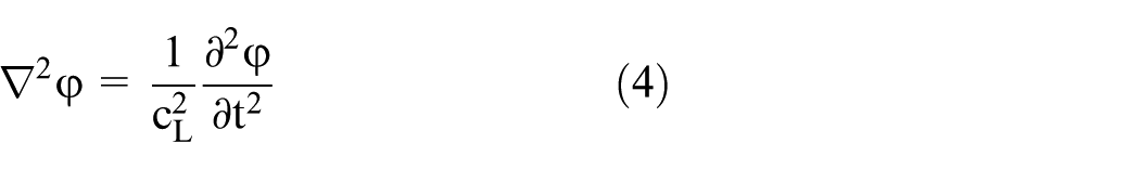

where


where
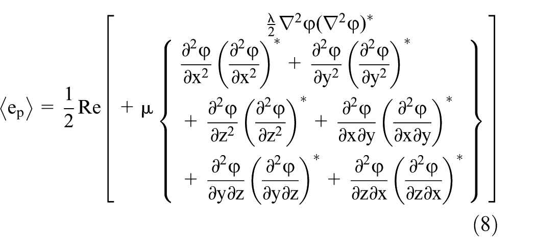
Since this article covers only the dilatational wave, it is assumed that there is no distortion wave type, and the displacement in the elastic solid can thus be described only with the scalar potential function. In the elastic solid without a distortion wave, the time-averaged potential energy density


where

where the unknowns,

In the case of small hysteretic damping, the wave numbers are well approximated using a Taylor approximation
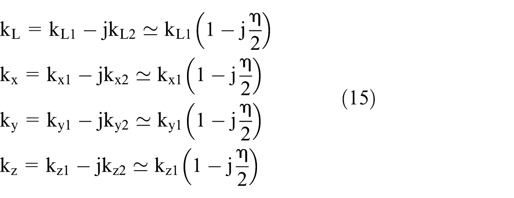
Substituting equation (15) into equation (14), the approximated dispersion relation is presented as

Substituting equation (13) into equations (8) and (9), the expressions for the time-averaged energy densities expanded in terms of the constants A, B, …, H can be written as


For the elastic solid medium, the total energy density is the linear combination of the kinetic and potential energy densities. The time-averaged total energy density of the solid can be expressed as

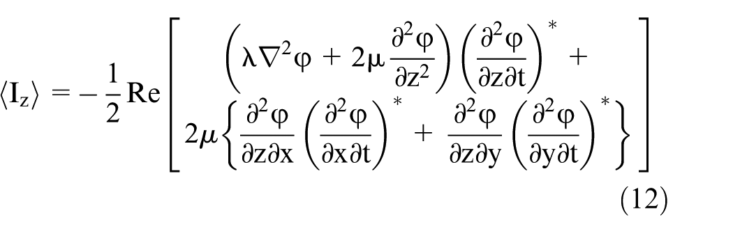
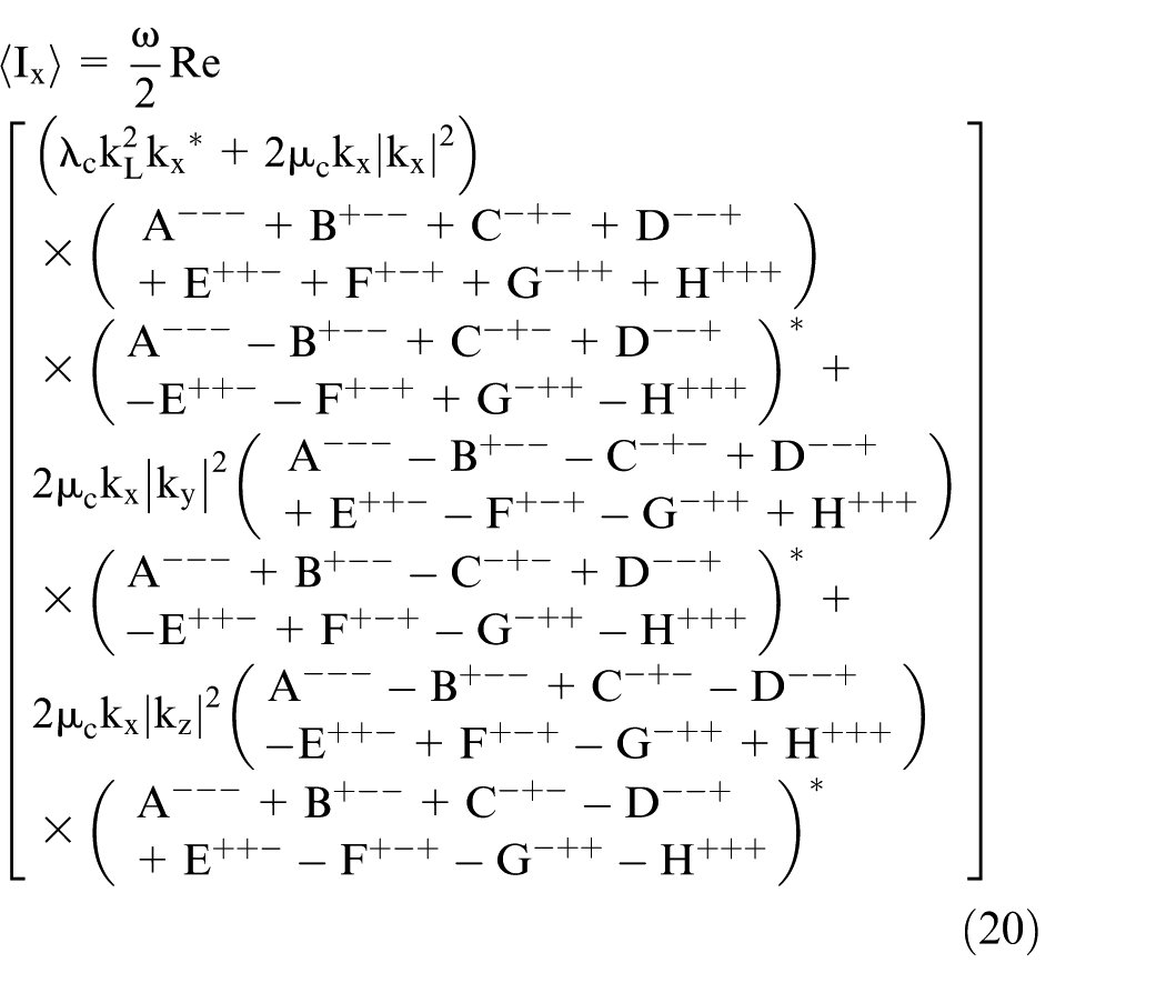
Substituting equation (13) into equations (10)–(12), the expanded expressions of each components of the time-averaged intensity are derived as


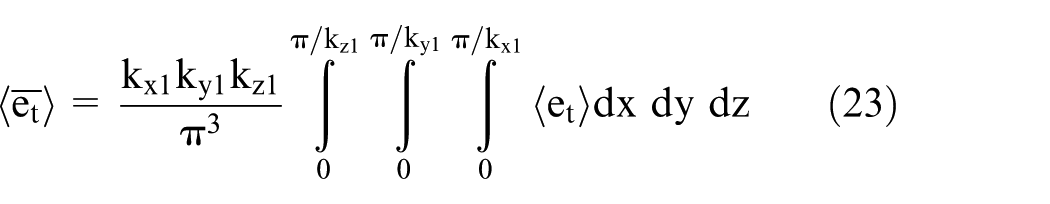
The relation equation between the energy density and intensity is required to obtain the energy governing equation. Here, no obvious relations can be found between the energy density and the intensity. The energy and intensity expressions can be simplified using a two-step process. The first is to neglect all the terms of order

where


where
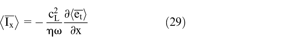


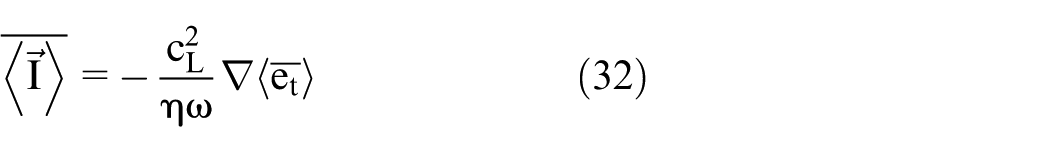
Consequently, rearranging equations (29)–(31), the relation equation between the time- and space-averaged energy density and intensity yields
For a steady-state condition, the energy balance equation of an elastic solid medium is expressed as

where

The gradient of the intensity in equation (33) can be expressed in terms of the second derivative of the energy density using the relation equation between the intensity and the energy density in equation (32), such that the energy governing equation for the dilatational wave in the elastic solid medium without input power can be derived as

Energy flow solutions for dilatational waves in the elastic solid medium
This section performs an analysis of a vibrating solid cube excited by spherical cavity source subjected to internal pressure by solving equation (35) using a Fourier series technique to find the energy density distributions. Since this study develops energy flow model for the dilatational wave in 3D elastic solids, the conditions of the structure are set so that only the dilatational wave exists in the structure, not the distortion wave.
The model used in these analyses is cube-shaped and contains a spherical cavity source at position

Cube shape structure with spherical cavity.
The spherical symmetric cavity surface excited by time-varying-but-uniformly applied normal pressure emanates only the dilatational wave, and the six faces of the cube are constrained by the traction-free condition, so the resulting waves generated from the spherical source and reflecting waves from the boundary can exist only as dilatational waves. Thus, it is reasonable to assume that there is no distortion wave for this example. If the diameter of the source is relatively smaller than the cube dimension, the spherical cavity source can be considered as simple monopole source.
When the spherical source is applied at
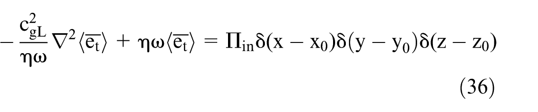
where

where

where

where


Validation
In this section, the results of the energy density obtained from the EFA are compared to those calculated using NASTRAN. In general, the FEA is optimized at the low-frequency range because the lower the frequency, the smaller the error. Contrary, because of the statistical approach, the EFA has the characteristic that the error decreases as the frequency increases. Because of the different characteristics of the two methods, in order to validate EFA with FEA, verification frequency was selected as the highest frequency of the reliable frequency range of FEA.
The cube model that is applied in this verification has a size of

The material properties are set to those of steel (Young’s modulus
Figure 2 shows the FE model used for NASTRAN analysis. Since the shape and boundary conditions of the structure are symmetrical, one-eighth of the cube is modeled to improve the efficiency of the analysis, and the convergence test was performed according to the number of elements. The total number of elements constituting the FE model used for the verification is about 420,000.

FE model used for NASTRAN analysis.
In the first example, the exciting frequency is

Energy density distribution of the elastic cube on quarter of mid-cross section when

Energy density distribution of the elastic cube when
FEA is inapplicable in high-frequency problem because the uncertainty of the system increases and the computational error is accumulated as the frequency increases. However, since the EFA is based on statistical assumptions, the error is reduced as the frequency increases. Therefore, it is possible to analyze the medium- to high-frequency range that cannot be performed by conventional FEA or BEA.
The results obtained from the energy flow method for the high-frequency problem are shown below. In the second example, EFAs at two different frequencies
The distributions of the energy densities on a quarter of the mid-section are shown in Figures 5 and 6. The results of the energy densities calculated from the EFA do not fluctuate locally, but decrease smoothly throughout the whole structure, as expected. The maximum/minimum values of the energy density at frequencies of

Energy density distribution of the elastic cube on quarter of mid-cross section when

Energy density distribution of the elastic cube on quarter of mid-cross section when
The last example implements EFAs for two different damping factors. Figures 7 and 8 show the results of the energy density for damping loss factors eta = 0.01 and 0.06, respectively, at a frequency f = 700 Hz. The maximum/minimum values of the energy density for a damping loss factors of η = 0.01 and 0.06 are 61.4/50.1 dB and 67.7/32.6 dB, respectively. The difference in the energy density between the maximum and minimum values is known to increase as the damping loss factor increases, which suggests that the global variation of the energy density increases with a high damping loss factor.

Energy density distribution of the elastic cube on quarter of mid-cross section when

Energy density distribution of the elastic cube on quarter of mid-cross section when
Conclusion
This study newly developed the vibrational energy governing equations for elastic 3D solid in order to extend the range of applications of the EFA to 3D vibrational problems. The energy density and intensity in 3D elastic solids, obtained from the exact elasticity equation for the dilatational wave in terms of the scalar potential function, is calculated to derive the energy differential equation for the dilatational wave. Time- and space-averaging were applied to derive the energy density and intensity assuming that the structural damping is small. The energy governing equation for a 3D elastic solid is derived by developing the relationship between the time- and space-averaged energy density and intensity.
The developed energy flow model for dilatational wave was applied to the analysis of vibrating cube-shaped structure by a spherical cavity source. And the developed energy governing equation was verified by comparing its results to those obtained with NASTRAN. A comparison of the results for the energy density distribution shows that the approximate energy density calculated using the derived energy flow model represents the global variation of the vibrational response quite well, with reliable results. In addition, as the exciting frequency and structural damping increase, the developed energy flow solutions spatially decrease more quickly.
All these taken together, when the developed energy flow model is applied to the 3D structure, it can analyze the vibration problem of the high-frequency range which is impossible with the conventional FEM and boundary element method (BEM). Also, if energy flow model for distortion waves is developed in the future, it will be possible to extend the application range of EFA to arbitrary shape structures having general boundary conditions.
Footnotes
Handling Editor: Daxu Zhang
Declaration of conflicting interests
The author(s) declared no potential conflicts of interest with respect to the research, authorship, and/or publication of this article.
Funding
The author(s) disclosed receipt of the following financial support for the research, authorship, and/or publication of this article: This research was funded by Advanced Naval Vessels Research Laboratory, Seoul National University, Seoul, Korea. Also, supported by Research Institute of Marine Systems Engineering, Basic Science Research Program through the National Research Foundation of Korea (NRF) funded by Ministry of Education, Science and Technology (2016R1D1A1A09918294, 2015R1D1A 1A01060387).