
Abstract
Energy flow analysis (EFA) is developed to predict the vibrational energy density of beam structures with both full free layer damping (FFLD) and partial free layer damping (PFLD) treatments in the high frequency range. Both equivalent flexural stiffness and structural damping loss factor of a beam with free layer damping are obtained using the equivalent complex stiffness method. Then the energy density governing equation considering high damping effect is derived for a beam with FFLD treatment. Following obtainment of the energy transfer coefficients at both ends of free damping layer, the energy density within a beam with PFLD treatment is evaluated by solving the presented energy governing equation. To verify the proposed formulation, numerical simulations are performed for the pinned-pinned beams with FFLD and PFLD treatments. The EFA results are compared with the exact solutions from wave analysis at various frequencies, and good correlations are observed between the developed EFA results and the exact solutions.
Keywords
Introduction
As one of typical structural components, lightweight beams are extensively used in mechanical and aerospace engineering in recent years. However, these lightweight beams are always sensitive to high frequency vibration excited by noise, turbulent flow, engine vibrating, and so on. Particularly, the undesirable vibration possibly leads to failure and degraded performance of structures or machines. To prohibit the unfavorable vibration, free layer damping treatment is widely adopted in beam-type structures. Free layer damping treatment uses high damping viscoelastic materials firmly attached to the surface of the lightweight beams.1,2 Therefore, the high frequency vibration analysis of lightweight beams with free layer damping (FLD) is significant for the design of beam-like structures under high frequency excitation.
Over the last few decades, advances in technology have drawn attention to high-frequency noise and vibration. Statistical energy analysis (SEA), a representative stochastic energy-based method, is widely employed to predict time and space averaged response of structures at high frequencies.3–5 However, SEA has some difficulties in offering detailed information, such as the distribution of energy density at the local domain of interest. As an alternative method for high frequency vibration analysis, energy flow analysis (EFA) is a recently developed effective tool for the dynamic response of built-up structures at high frequency. Since the energy governing equation for EFA is a parabolic partial differential equation, the solution can present the spatial variation of energy densities. 6 The governing equations of EFA were developed for structural components such as rods,7–9 beams,7,8 membranes, 10 and plates.11,12 To predict the vibrational response of the coupled structures, the energy flow coupling relationships were derived at various joints of these structures like beam-plate,13,14 plate-plate,15,16 shell-shell, 17 and structure-to fluid,18–20 and acoustic21,22 field coupling. For structures in thermal environment, the energy density governing equation of beams with thermal effects was derived by Zhang et al., 23 whose work was afterwards extended by Wang et al. 24 to plates in non-uniform thermal environment. Recently, Yeo et al. 25 develop an energy flow model for a dilatational wave in 3D elastic solids vibrating at medium- to high-frequency ranges. Thus, EFA has been an efficient method for high-frequency structural vibration analysis.
However, few publications are available on the high-frequency vibration analysis of a structure with viscoelastic damping treatment. The previous energy flow models are mostly developed for low damping and homogeneous structures. Since a free layer damping structure uses high damping viscoelastic materials firmly attached to the surface of structural elements, the traditional energy flow models can’t accurately predict the dynamic behavior of the viscoelastic laminated structures. Thus, this paper motivates to develop a new energy flow model to predict the high-frequency response of beam structures with viscoelastic damping treatment.
The paper is organized as follows. Firstly, the energy density governing equation of a beam with full free layer damping (FFLD) treatment is derived from the energy balance equation, the energy transmission equation and the energy loss equation. Secondly, the energy transfer coefficients are deduced from wave theory to indicate how wave energy is distributed when the flexural wave propagates through a beam with partially free layer damping (PFLD) treatment. Then, in order to verify the developed energy flow model, various numerical analyses are performed for pinned-pinned beam structures with FFLD and PFLD treatments at several excitation frequencies. The developed EFA results are compared with exact wave solutions for different cases. Finally, some conclusions on the proposed EFA model are presented.
Energy flow model of a beam with FFLD treatment
Equivalent complex bending stiffness and structural damping loss factor
Figure 1(a) depicts a free layer damping beam structure, where

Section view of a beam with FFLD treatment. (a) a free layer damping structure and (b) a differential element of a laminated beam.
For a differential element of a laminated beam, as shown in Figure 1(b), the complex longitudinal strain

where
When the beam vibrates transversely under an external loading, the longitudinal force equilibrium is obtained. We have

By substitution of equation (1) into equation (2), the location of neutral axis of the laminated beam is written as

where
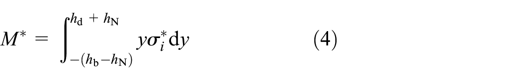
For a beam with FFLD treatment, the complex bending moment resulting from the complex longitudinal stress is given by

where
By substituting equations (1) and (5) into equation (4), the equivalent complex flexural rigidity of the laminated beam is written by

By substituting equation (3) into equation (6), the equivalent complex flexural stiffness of the laminated beam is obtained
where
According to the energy theory,
2
the equivalent complex flexural stiffness can be given by

where functions
Energy density governing equation
To perform the energy flow analysis of the laminated beam, the energy density governing equation is deduced from the energy transfer equation, the energy loss equation and the energy balance equation.
For a beam with FFDL treatment, excited by a transverse harmonic load

where
Hence, the general solution of equation (9) in arbitrary domain is written as

where


where

where

A pinned-pinned beam with FFDL treatment.
The first two terms of equation (10) are far-field solutions describing the propagating waves in the positive and negative x directions, respectively. The last two terms of equation (10) are near-field solutions describing the evanescent waves, which are dissipated rapidly more than one wavelength away from the boundaries and driving points.
26
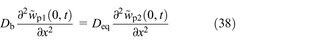
Departing from

where
Representation of waves arriving at and departing from boundaries of subdomain ①.
For a beam with high frequency vibration, the near-field solutions are much less than far-field solutions from equations (14) and (15) due to

The energy density at any cross section of a laminated beam is the sum of the kinetic energy density and the potential energy density associated with bending strain. The time averaged energy density can be represented as8,27

where bracket operator

To eliminate spatially harmonic terms in equations (17) and (18), a spatially averaged operation over a wavelength is applied to the time averaged energy density and intensity, as indicated by Wohlever.8,26 By substitution of equation (16) into equations (17) and (18), and following locally space averaging operation, the time and space averaged energy density and intensity are obtained as


where 〈¯〉 denotes the time and space averaged operation,
From equations (19) and (20), the energy transfer equation, representing the relationship between the time and space averaged energy density and intensity, can be expressed as
where
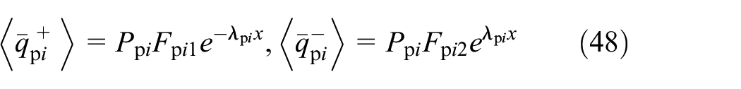
In addition, from equation (19), the relationship between the time-space averaged potential energy density and the total energy density can be derived as

where
From the work of Lase et al., 7 the energy loss equation for a laminated beam with high structural damping loss factor is

In a light damping homogeneous beam, the time-space averaged potential energy density is the same as time-space averaged kinetic energy density and hence the time-space averaged dissipated power is represented as8,26

However in a high damping beam, the time-space averaged potential energy density is different from time-space averaged kinetic energy according to equations (19) and (22). It implies that equation (24) derived from low damping assumption is unsuitable for high damping systems. From this, substituting equation (22) into equation (23), the energy loss equation for a laminated beam is rewritten as

For an elastic vibration system, the energy balance equation at the steady state can be described as

Where
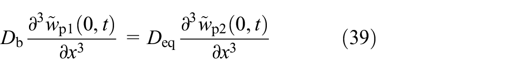
Substituting equations (21) and (25) into equation (26), the energy density governing equation of the laminated beam can be derived as

The conventional energy density governing equation is developed with low damping assumption by using lineally approximated wavenumber to evaluate the time and space averaged energy density and intensity. Unlike the traditional energy flow model which is only suitable for lightly damped systems, the developed energy density equation is deduced by using the exact wavenumber to evaluate the time and space averaged energy density and intensity due to high damping effect of the laminated beam.
Energy flow analysis
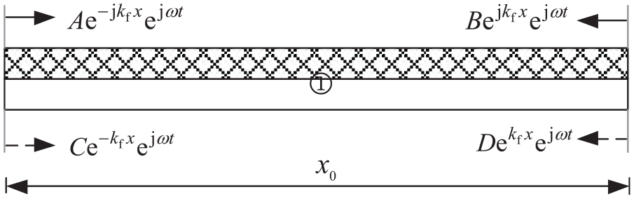
As shown in Figure 2, the laminated beam is divided into two subdomains ① and ② at the point

where
Substituting equation (28) into equation (27), there is
Substituting equation (28) into equation (21), the energy intensity of the ith subdomain of the laminated beam is written by

where
Because the energy intensity across the boundary is zero for a pinned-pinned beam, the following intensity boundary conditions can be written as

At the driving point


For the solutions of equation (27), it is necessary to convert the external load to the input power. By impedance method, time averaged input power can be obtained as 28

Substituting equations (32)∼(34) into equations (28) and (30), the flexural energy density and intensity for the vibrating laminated beam can be calculated.
Energy flow model of a beam with PFLD treatment
Energy transfer coefficients
For the coupled structures, the key step of EFA is to the energy transmission and reflection coefficients in the joint. Figure 4 depicts a beam with PFLD treatment, which can be treated as coupled collinear beams. The coupled beam is divided into four parts, by the driving force and both ends of the free damping layer, respectively. The lengths of the base beam and the free damping layer are specified to be

A beam with PFLD treatment.
In the wave transmission approach, the energy transfer coefficients are evaluated from the displacement solutions of infinite members. Figure 5 shows a semi-infinite bold beam jointed to a semi-infinite beam with free damped treatment at

where

where

Transmitted and reflected flexural waves.
At the joint, the moment and shear force satisfy the equilibrium equation as below
The other two conditions impose continuity of transverse displacement and slopes. The continuity of transverse displacements and slopes lead to the following relationship


Equations (38)~(41) are solved simultaneously for the complex amplitudes,

According to equation (42), the energy reflection and transmission coefficients can be expressed as


The principle of conversation of energy applied to the semi-infinite beam joint model is

From equation (45), the relationship between the energy reflection and transmission coefficients is subjected to
Energy flow analysis
Similar to the fully laminated beam, the flexural energy density and intensity of the partially laminated beam, as shown in Figure 6, is expressed as


where the subscripts i denotes the ith subdomain of the partially laminated beam. The energy intensity of positive and negative traveling waves in each subdomain can be expressed as
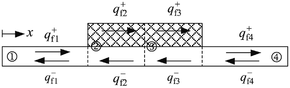
Energy transfer of flexural wave.
in a similar way,
For a pinned-pinned beam, the energy boundary conditions at both ends are expressed as

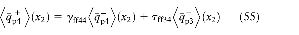
At the driving point between subdomain ② and ③, the continuities of energy density and the equilibriums of energy flow are satisfied


From the conversation of energy, the net energy flow away from the joints in each subdomain, can be written as


where
From reciprocity and conversation of energy principles, we have

Similar to the previous case, the time averaged input power of partially laminated beam can be obtained using the impedance of finite beam. Substituting equations (49)∼(56) to equations (46)∼(48), the energy densities for the coupled beam can be predicted.
Verification and discussion
In order to verify the developed energy flow analysis method for laminated beams with FFLD and PFLD treatments, some numerical simulations are performed on beams with both pinned end conditions, as depicted in Figures 2 and 4. The energy density distribution obtained by the proposed EFA model are compared with the exact time and time-space averaged solutions obtained by wave analysis method (refer to Appendix A and B).
A beam with FFLD treatment
The base beam is made of aluminum alloy, whose material properties and dimensions are as follows:
Figures 7 to 10 illustrates the energy density distribution by EFA when the analysis frequencies are 800 Hz, 2 kHz, 4 kHz, and 6 kHz, respectively. As in all the following figures, the reference energy density is 10−12J/m. The exact time averaged energy density fluctuates spatially. Because the spatially harmonic terms of energy density are excluded in EFA, the EFA predictions are smooth representing the trend of the exact time averaged energy density. It is also found that the spatially harmonic terms lessen with increasing frequency, which implies that the EFA predictions are more accurate at higher frequencies. However, it is observed that the developed EFA results obviously differ from the exact time averaged wave solution in the vicinity of the driving point and the boundaries due to negligence of evanescent wave. Fortunately, this difference only exists within one or more wavelengths away from the driving point and the boundaries. As shown in Figure 11, the far-field solutions representing travelling waves are far greater than the near-field solutions representing evanescent waves except for neighborhood of the driving point and the boundaries, as a result of the rapid dissipation of the evanescent wave. Particularly with increasing frequency, the far-field solutions overwhelm the near-field solutions. It indicates that the developed EFA solutions with negligence of near-field solutions are more consistent with the exact time averaged wave solution at higher analysis frequencies, as depicted in Figures 7 to 10. In addition, it is obviously observed that the energy density abruptly decays near the driving point owing to the dissipation of energy caused by high damping. The attenuation of energy density is larger at higher frequency. Moreover, the developed EFA results are consistent with the exact time and space averaged solutions obtained by wave analysis.

Energy density distribution of a beam with FFLD treatment under excited frequency of 800 Hz.
Energy density distribution of a beam with FFLD treatment under excited frequency of 2 kHz.
Energy density distribution of a beam with FFLD treatment under excited frequency of 4 kHz.
Energy density distribution of a beam with FFLD treatment under excited frequency of 6 kHz.

Comparison of displacement between travelling and evanescent waves in subdomain ①: (a) in positive x direction and (b) in negative x direction.
A beam with PFLD treatment
As shown in Figure 4, the free damping layer is partially laid above the central region of the base beam. The geometrical dimensions except the free damping layer length, the material properties as well as boundary conditions of the partially laminated beam are the same as those of fully laminated beam as depicted in Figure 2.
Figures 12 to 15 show the energy density distribution by EFA when the analysis frequencies are 800 Hz, 2 kHz, 4 kHz, and 6 kHz, respectively. As in all the following figures, the reference energy density is 10−12J/m. The developed EFA result and exact time averaged solutions differ near the point force and the boundaries because the developed energy flow model is derived by exclusion of the evanescent wave. Despite this, the developed EFA results are in good agreement with the global variation of the exact time averaged solutions at each frequency. As expected, there is a jump in the developed energy density by EFA at the two joints between bold beam and laminated beam. Nevertheless, the developed EFA results present a smooth response away from the discontinuities resulting from dissimilar cross-sectional area and material properties. It is also noted that the energy density severely attenuates near the driving point due to the dissipation of energy caused by high damping. The attenuation of energy density is larger at higher frequency. Additionally, the developed EFA results concur with the exact time and space averaged solutions obtained by wave analysis.
Energy density distribution of a beam with PFLD treatment under excited frequency of 800 Hz.
Energy density distribution of a beam with PFLD treatment under excited frequency of 2 kHz.
Energy density distribution of a beam with PFLD treatment under excited frequency of 4 kHz.
Energy density distribution of a beam with PFLD treatment under excited frequency of 6 kHz.
Conclusion
The energy density governing equations for beam structures with FFLD and PFLD treatments are developed to predict their high-frequency dynamic response by EFA method. Using equivalent complex stiffness method, the equivalent complex bending stiffness and structural damping loss factor are obtained to constitute the motion equation of a beam with FFLD. Due to high structural damping loss factor, the energy density governing equation of a beam with FFLD is derived by using the exact wavenumber obtained without linear approximation to evaluate the time and space averaged energy density and intensity. For a beam with PFLD, the transmission and reflection coefficients are derived to determine how wave energy is distributed when the flexural wave propagates through both ends of the free damping layer.
To verify the developed energy flow model, the pinned-pinned beams with FFLD and PFLD treatments are adopted in the numerical simulations. The developed EFA results are compared with the exact solutions from wave analysis. The developed EFA results smoothly represent the trend of time averaged wave solutions at various analysis frequencies, and are in good agreement with time and space averaged wave solution. Particularly, to obtain the energy density distribution within a beam with PFLD treatment, the energy transfer coefficients is derived from exact wavenumber without linear approximation because the influence of high damping is not simplified. Furthermore, it is found that the energy density within the laminated beam is more significantly attenuated by high damping effect at higher frequencies. The proposed method is expected to be useful for the prediction of the high frequency vibration of structures with FFLD and PFLD treatments.
Footnotes
Appendix A
Appendix B
Handling Editor: James Baldwin
Declaration of conflicting interests
The author(s) declared no potential conflicts of interest with respect to the research, authorship, and/or publication of this article.
Funding
The author(s) disclosed receipt of the following financial support for the research, authorship, and/or publication of this article: The presented work is supported by National Natural Science Foundation of China (Grant No. 51505096) and Natural Science Foundation of Heilongjiang Province of China (Grant No. LH2020E064).