
Abstract
It is a key part for micro seismic crack detection, mechanical equipment operation state and structural health monitoring to measure high frequency vibration. A kind of FBG acceleration sensor based on flexure hinge is proposed targeting at the problem of existing medium-high-frequency FBG acceleration sensor’s low sensitivity. Two FBGs are fixed on L-shaped support in a differential arrangement to improve sensitivity of sensor and eliminate adverse effects caused by temperature changes. Matlab and ANSYS software are used to simulate, analyze and optimize sensor. According to the simulation results, the real sensor is made, and the sensor calibration experiment is carried out. Research results show that resonant frequency of sensor is about 1700 Hz and has good linearity in flat range of 50–1000 Hz. Sensitivity of sensor can reach 18.9 pm/g, while linearity is higher than 99%, and temperature sensitivity is merely 0.074 pm/°C. Research results provide reference for researching and developing the same type of sensor, and further improving optical fiber acceleration sensor sensitivity.
Introduction
Pickup and measurement of vibration signal is one of basic and important research directions in fields of micro seismic crack detection, mechanical equipment operation status and structural health monitoring, among which medium-high-frequency vibration signal contains important fault information. It can timely grasp real-time status of equipment, environment and engineering through real-time monitoring of medium-high-frequency vibration signal, effectively avoiding safety accidents.1–3 Acceleration sensor is key equipment for monitoring object vibration. Traditional acceleration sensor is mainly piezoelectric, resistive and capacitive,4,5 which has advantages of low cost and mature technology. But, electrical acceleration sensor is vulnerable to external magnetic field interference, complicated wiring, serious attenuation when transmitting signals over a long distance and other shortcomings.6,7 As a special kind of optical fiber sensing element, Fiber Bragg Grating (FBG) has advantages of anti-electromagnetic interference, anti-optical power fluctuation, small volume and light weight. It serves as a compensation for shortcomings of electrical acceleration sensors in field of medium-high-frequency vibration measurement.8–10
FBG acceleration sensor is a branch of FBG sensor that has made great progress in recent years. 11 Yongxing Guo et al. 12 designed a new accelerometer, whose mass block is welded with metal coated optical fiber, and both ends of optical fiber fixed on shell. Natural frequency of sensor is 3600 Hz and sensitivity is only 1.7 pm/g. Wang et al. 13 proposed a kind of Fiber Bragg Grating acceleration sensor with elastic steel pipe structure, which has good linear response at 0–1200 Hz and sensitivity can reach 4.01 pm/g. Zhu et al. 14 proposed a double Fiber Bragg Grating acceleration sensor with lantern shaped metal shell. Such sensor has strong anti-transverse interference capability, its resonant frequency is about 1175 Hz and its sensitivity is 9.4 pm/g. Dai et al. 15 designed a double hinge accelerometer with a resonant frequency of about 3000 Hz, which can be used for medium and high frequency measurement. Bottleneck of low sensitivity of FBG acceleration sensor in measuring medium-high-frequency vibration still exists although frequency range that can be measured by medium-high-frequency FBG acceleration sensor is gradually improved in past research results.
An FBG acceleration sensor based on flexure hinge is proposed targeting low sensitivity of existing FBG acceleration sensor in measuring medium-high-frequency vibration. Such sensor is designed as a whole to reduce mechanical fatigue and friction loss that may occur during assembly of various parts. Two FBGs are symmetrically pasted between mass block and L-shaped support by two-point pasting method to weaken influence of temperature on sensor, and differential operation is used to improve sensitivity of sensor. The theoretical model of the accelerometer is established, and the working principle is theoretically deduced. Influence of structural parameters on sensitivity and resonant frequency of sensor is analyzed by Matlab software. Dynamic characteristics of sensor are analyzed by finite element method combined with ANSYS software, and the sensor samples are produced. Experiments are carried out to test the dynamic property of the fabricated sensor samples.
Sensor design
Sensor structure
Sensor structure contains base, flexure hinge, mass block and L-shaped support. Such sensor adopts an integrated design and is made of complete spring steel through wire cutting and heat treatment. So there will be no mechanical friction in practical working conditions, and performance of sensor can be fully exerted to the greatest extent. The two same FBGs are pasted in optical fiber groove of mass block and L-shaped support with UV glue. FBG is prestressed in pasting to prevent chirp effect. Specific structure is shown in Figure 1.
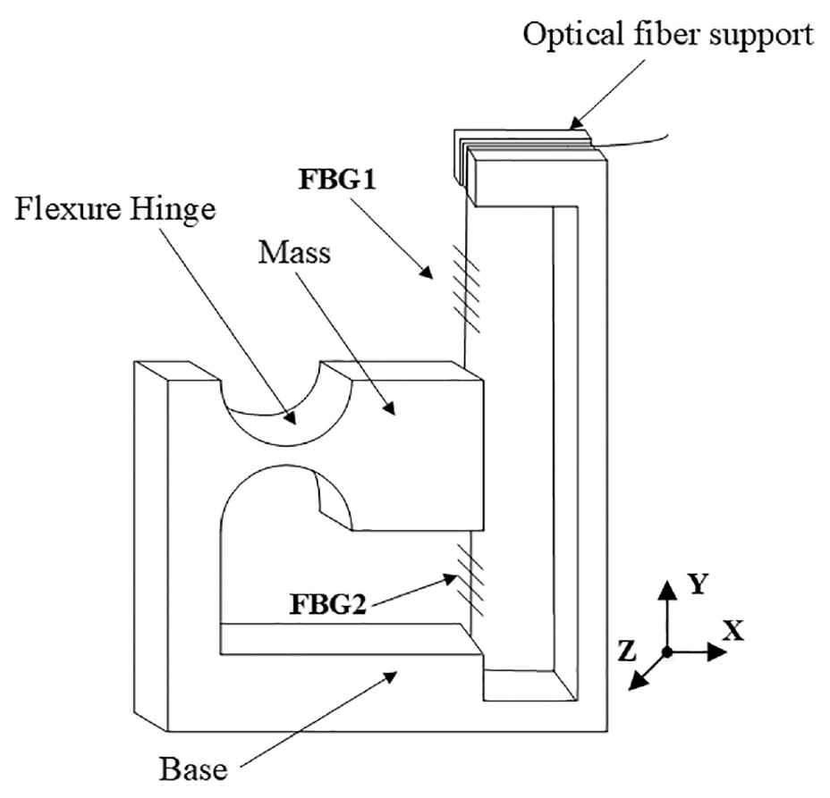
Schematic diagram of sensor structure.
As shown in Figure 1 that L-shaped bracket medium-high-frequency dual FBG acceleration sensor takes FBG as sensing element to convert object high-frequency vibration signal into FBG center wavelength offset signal. Mass block rotates slightly around center of flexure hinge under action of inertial force when sensor is excited by vibration signal in Y direction, and FBGs at both ends of mass block have small axial telescopic deformation, one end is stretched and the other end is contracted. Wavelength change caused by axial strain is the same and direction is opposite as a result that central wavelengths of the two FBGs are similar and all characteristics are the same. So sensitivity of sensor is twice that of a single FBG, and adverse effect of temperature change can be eliminated after reflection spectrum difference operation of two FBGs.
FBG stretching amount amplification mechanism
Common Fiber Bragg Grating acceleration sensors based on flexure hinges are horizontally placed ones. Influence of FBG natural vibration characteristics on performance of sensor in high frequency vibration measurement has to be considered in this placement method. The key to improve the sensitivity of FBG acceleration sensor is to adjust the sensor structure, weaken the influence of FBG natural vibration characteristics on the sensor performance, and increase the variation of FBG central wavelength. So FBG in this paper is placed vertically on L-shaped support, Its principle is shown in Figure 2.
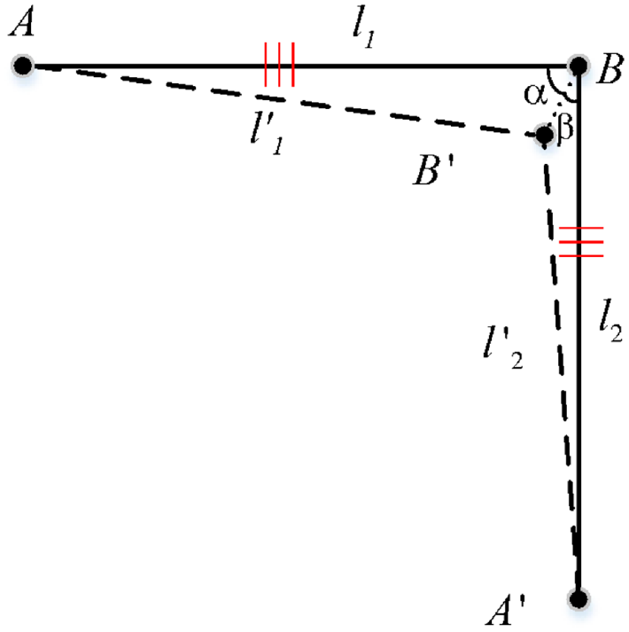
Schematic diagram of FBG stretching amount amplification.
As shown in Figure 2, Principle of FBG stretching amount amplification is shown in Figure 2. In case sensor does not detect vibration signal, length of horizontally placed fiber grating AB is
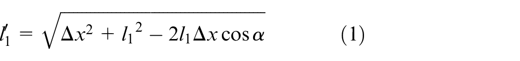
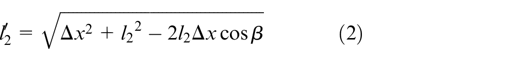
Then stretching amount of Fiber Bragg Grating
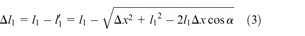
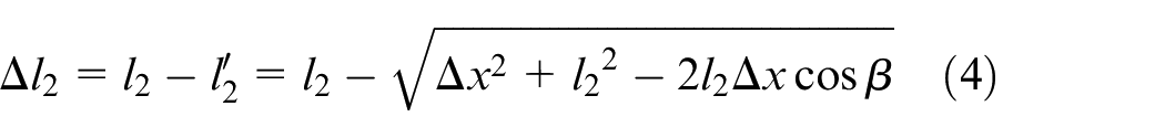
With conditions where sensor signal is a micro amplitude vibration signal,
Sensor sensitivity analysis
Because the vibration amplitude of high-frequency vibration signal is small and decays rapidly, the mechanical analysis of the sensor is carried out. XOY plane of sensor structure is taken as per Figure 1 to establish mechanical model, replacing flexure hinge with ideal hinge, regarding mass block as rigid body without deformation, while only considering elastic coefficient of optical fiber and hinge part. And vibration model of sensor is shown in Figure 3.
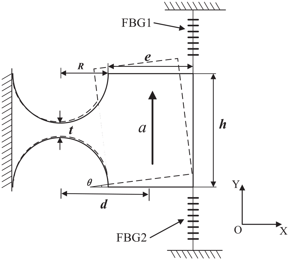
Sensor vibration model.
It can be learnt from Figure 3 that R is radius of flexure hinge, t is thickness of hinge, e is length of mass block, and h is height of mass block. When acceleration excitation signal acts on sensitive direction of sensor, mass rotates slightly around center of flexure hinge under action of inertial force, and system achieves torque balance under action of inertial force, so the following can be made:
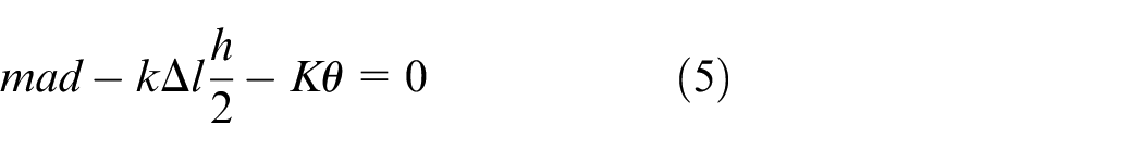
Where,
Sensor sensitivity
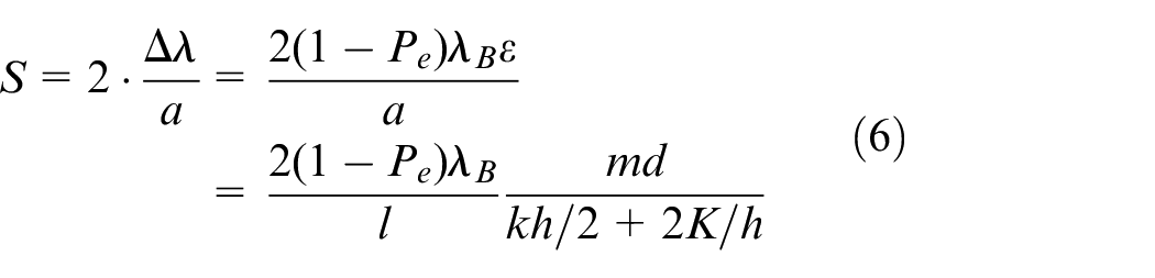
Where,
In equation (6) that sensitivity is not only restricted by size of sensor, but also affected by hinge stiffness, so hinge stiffness
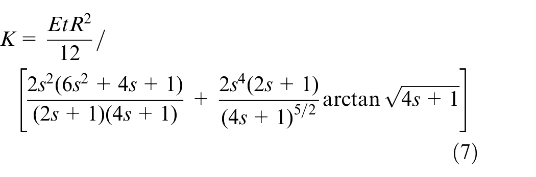
Where
Sensor resonance frequency analysis
Resonance frequency is another important parameter of acceleration sensor. When external resonant frequency reaches resonance frequency of sensor, sensor will resonate with vibrating object, and amplitude increases sharply. So, the higher the resonant frequency, the wider the available frequency band of sensor, and the more high-frequency signals can be measured. Supposing inertia moment of mass rotating around hinge center is
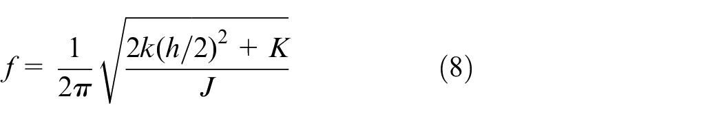
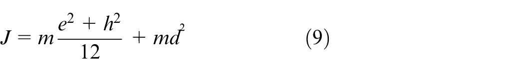
Where inertia moment
Impact analysis of structural parameters
Influence of structural parameters on sensors
Vibration characteristics and measurement range of sensor have something to do with resonant frequency of sensor. It is necessary to optimize design to increase sensor sensitivity S as much as possible and take an appropriate value for resonant frequency
First of all, influence of mass block length
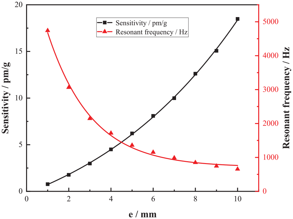
Effect of mass block length
It can be learnt from Figure 4 that sensor sensitivity S increases with increase of length
Secondly, influence of mass block height on sensor sensitivity and resonant frequency is analyzed. At this time, take
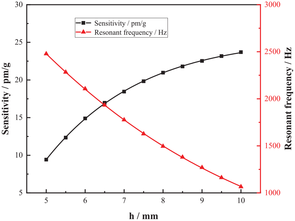
Influence of mass block height on sensor sensitivity and resonant frequency.
It can be learnt from Figure 5 that sensor sensitivity S increases with increase of mass block height
Finally, influence of hinge thickness
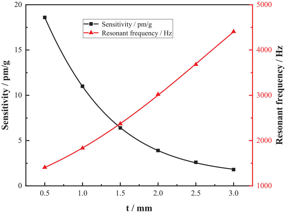
Effect of hinge thickness
It can be learnt from Figure 6 that sensor sensitivity S decreases with increase of hinge thickness
Multiple groups of data are taken for test and simulation in order to make sensor have wide measurement frequency band and high sensitivity. Optimized parameter results are
Finite element analysis
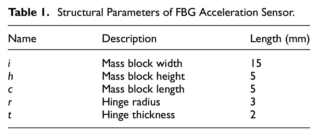
To further study dynamic response characteristics of sensor, solid model is firstly established by Solidwork. Secondly, established assembly model is imported into ANSYS Workbench software. And designed sensor is finally analyzed by finite element method. Key parameters of sensor are shown in Table 1.
Structural Parameters of FBG Acceleration Sensor.
Fixed constraint is firstly applied to bottom of sensor model, and external load of standard earth gravity acceleration g is applied to the whole sensor. Modal simulation analysis of model is carried out through grid division, and strain cloud diagram of model is obtained, as shown in Figure 7.
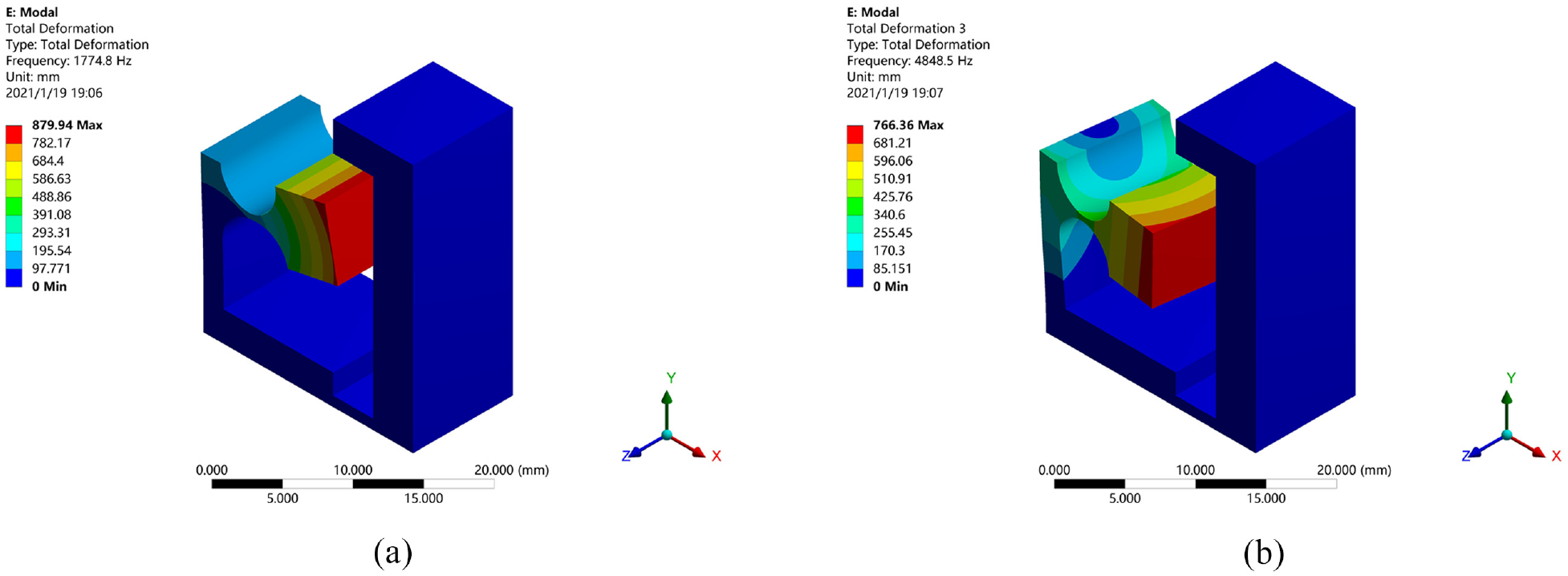
Sensor modal analysis: (a) first order model and (b) second order model.
As shown in Figure 7(a) that natural frequency of the structure is 1774.8 Hz. According to Figure 7(b) that the second-order natural frequency of sensor is 4848.5 Hz, which is similar to the theoretical analysis results, The reason for the small error may be: the division accuracy selected when the sensor is meshed is too rough, which leads to a slight deviation between the final simulation result and the theoretical value. ANSYS simulation results shows difference between the first and second natural frequencies of sensor is large, which shows that cross coupling of sensor is small where cross interference reduction is possible.
Sensor calibration experiment
The FBG used in the sensor is three fiber Bragg gratings in the same batch, whose central wavelength is 1560.5 nm, reflectivity is ≥90%, and the length of the FBG gate region is 5 mm. The reflection spectrum is shown in Figure 8.
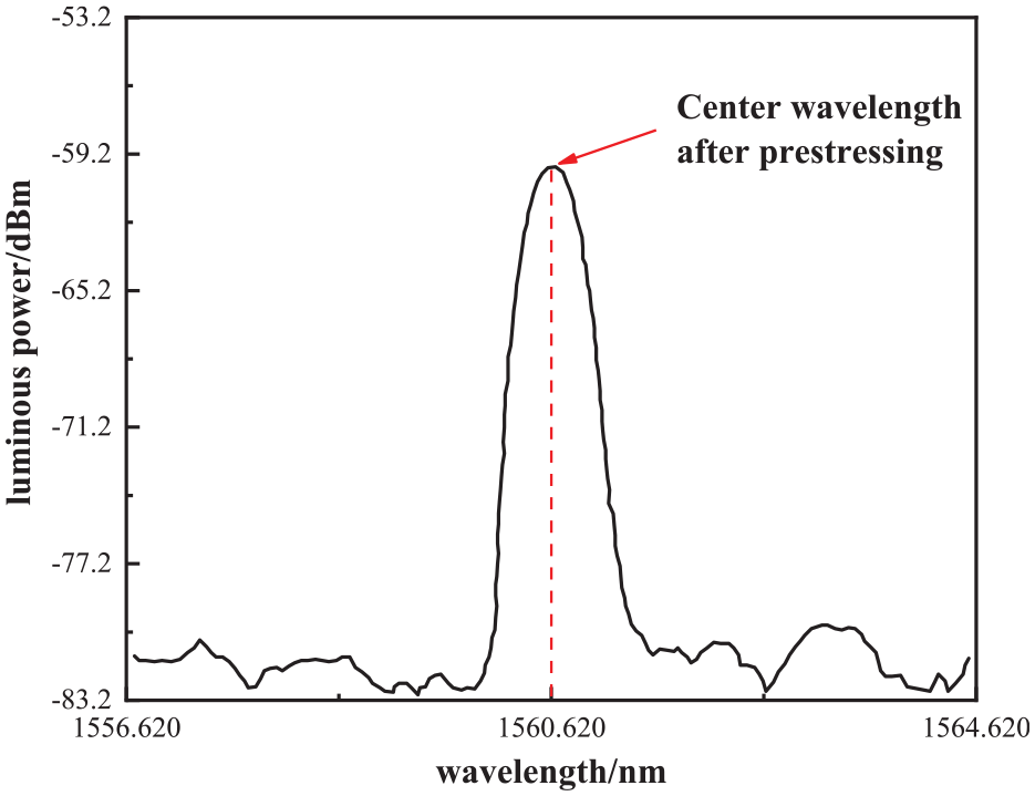
The spectrum of the FBG sensor at room temperature.
The apparatus for experimental test of the sensor principally included function signal generator, signal amplifier, standard exciter, FBG demodulator, computer, etc. The test was performed with a function signal generator (DG1022) from RIGOL Technologies with a sampling rate of 1 GSa/a, 14 quasi-waveform functions and abundant standard interfaces designed for users to remotely control the data transmission of instruments and USB interfaces via Web. The signal amplifier (MWY-TZQ50) was manufactured by Beijing Weiyun with a frequency response range of 1–15,000 Hz and an SNR of more than 75 dB to work with the function signal generator to amplify the function signals. The FBG demodulator (MWY-FBG-CS800) was also manufactured by Beijing Weiyun, which has 8 signal acquisition channels, each channel can collect optical signals independently, the sampling frequency can reach 1 kHz and a built-in laser source to deliver the transmitted light waves to FBG acceleration sensor on the vibration exciter system via optical fibers; additionally, the FBG demodulator received the FBG reflection spectrum, conducted spectral analysis and data acquisition inside, and transferred the acquired data to the computer in the end. The experimental test system established with above-noted devices for the multi-cantilever beam low-frequency FBG acceleration sensor is shown in Figure 9(b)
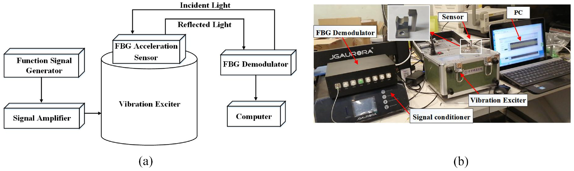
Sensor calibration experimental system: (a) schematic diagram of vibration experiment system and (b) physical drawing of vibration experiment system.
Dynamic calibration and performance test are needed to calibrate performance parameters of sensor. Sensor base is fixed on vibration table and kept perpendicular to vibration direction of vibration table. FBG is introduced into two channels of wavelength demodulator, and data is displayed and recorded in real time by computer.
Amplitude frequency response test
Firstly, sine excitation signal with output acceleration value of 5 m/s2 is adjusted by signal generator, and frequency sweep test is carried out for sensor in order to study amplitude frequency characteristics of sensor. Sweep frequency range is selected as 10–2200 Hz and step length is 300 Hz as per simulation results. Approximate range of resonant frequency of sensor is determined, and then step length is taken as 100 Hz for repeated experiments. Then reread sampling is performed in steps of 50 Hz near the peak range. In the end, amplitude frequency characteristic curve of sensor is obtained as shown in Figure 10.
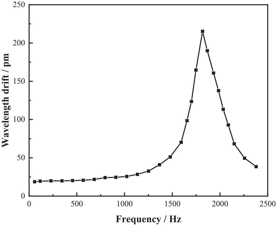
Amplitude frequency characteristic diagram of sensor.
It can be learnt from Figure 10 that resonant frequency of sensor is about 1700 Hz and has a relatively flat response at 50–1000 Hz. Experimental value of the first-order frequency of sensor deviates from theoretical value because prestress of optical fiber is not considered in theoretical analysis and finite element simulation, and material properties of actually assembled sensor are different from those in theoretical analysis and finite element.
Sensitivity coefficient test
Test points with acceleration higher than 500 Hz are no longer continuous due to limitation of shaking table. Signal generator shall be adjusted so that output frequencies of shaking table are 160, 325, and 495 Hz, so as excitation acceleration value of shaking table with a variation range of 1–14 m/s2 and a step size of 1 m/s2, in order to obtain sensitivity characteristics of sensor, and data of central wavelengths of the two FBGs is repeatedly recorded. Results are shown in Figure 11.
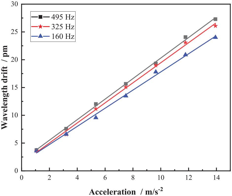
Linear diagram of sensor sensitivity.
It can be learnt from Figure 11 that under frequency of 160 Hz, acceleration sensitivity of sensor is 17.50 pm/g, and fitting determination coefficient R2 = 0.9970. Under frequency of 325 Hz, acceleration sensitivity of sensor is 19.56 pm/g, and fitting determination coefficient R2 = 0.9982. Under frequency of 495 Hz, acceleration sensitivity of sensor is 19.82 pm/g, and fitting determination coefficient R2 = 0.9986. To conclude, sensitivity of medium-high-frequency dual FBG acceleration sensor with L-shaped support is about 18.96 pm/g and resonant frequency is about 1700 Hz. It can be used to detect vibration signals within 50–1000 Hz, and its sensitivity is higher than that of other medium-high-frequency FBG acceleration sensors.
Lateral anti-interference capability
Characteristic of anti-lateral interference is also an important performance index to be considered for single degree of freedom acceleration sensor. Bottom of sensor is fixed on side of horizontal shaking table in this experiment, so that vibration direction is perpendicular to direction of vibration measuring spindle of sensor in order to study lateral anti-interference characteristics of acceleration sensor. Sinusoidal excitation signal with acceleration of 10 m/s2 and frequency of 495 Hz is set. Lateral anti-interference characteristic curve of sensor is obtained by comparing drift of output wavelength with results in direction of vibration measuring spindle, as shown in Figure 12.
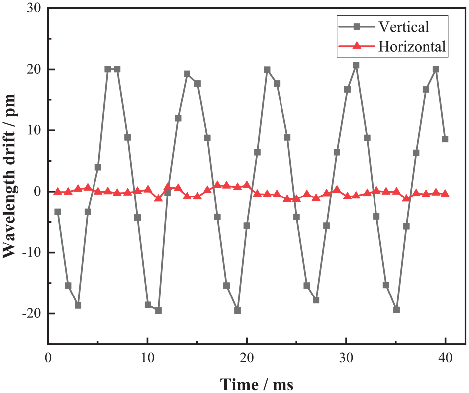
Characteristic diagram of sensor cross interference.
It can be learnt from Figure 12 that lateral response and transverse response of sensor are 20.3 pm and 1.8 pm respectively, and wavelength drift of transverse response is only 8.87% of lateral response, showing that sensor can be regarded as a single degree of freedom vibration under vibration conditions, and has strong lateral anti-interference capability.
Self-compensation capability of temperature
Self-compensation capability of temperature is an important capability for FBG acceleration sensor, which is directly related to working capability of sensor in large temperature difference environment. Sensor is placed in high and low temperature damp heat test chamber (MQ-TH1000F-2N, temperature range −70°C to +150°C), and FBG is connected to FBG wavelength demodulator through wiring outlet on outer wall of high and low temperature damp heat test chamber. Oven temperature changes from −20°C to 60°C in steps of under 10°C. It is held for 30 min after each temperature rising to corresponding node of temperature, and FBG center wavelength offset is repeatedly collected at this time node for many times. In the end, temperature change curve of sensor center wavelength is obtained, as shown in Figure 13.
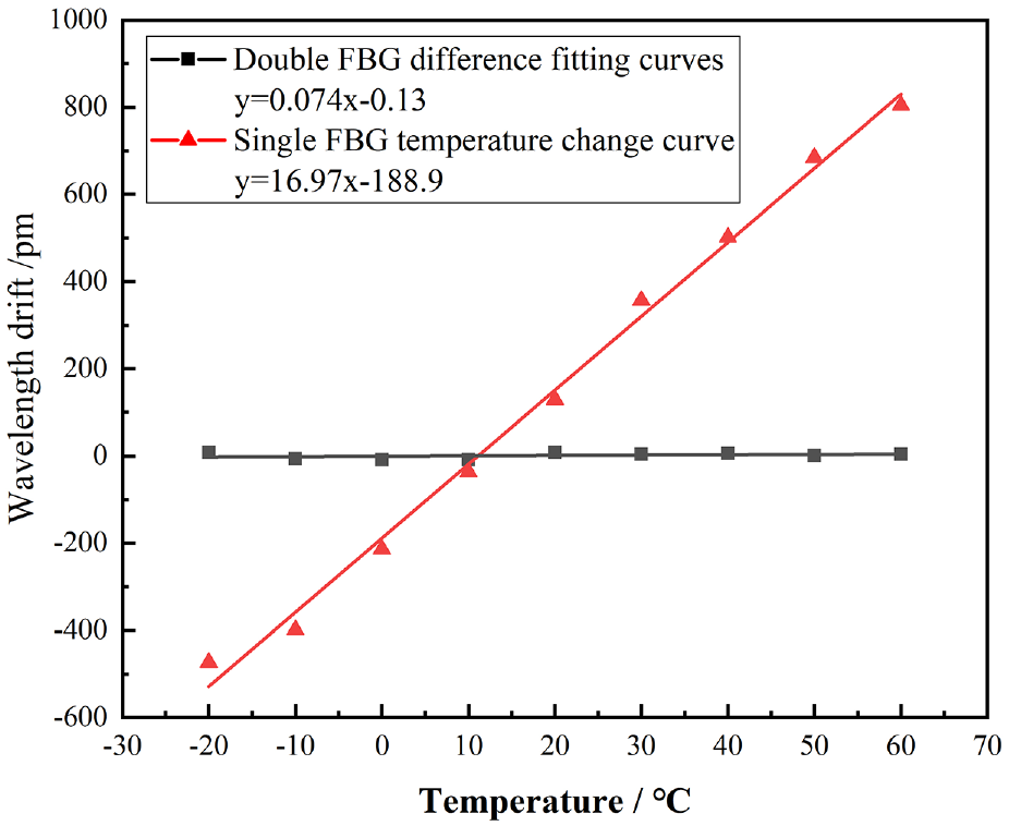
Temperature self-compensation characteristics.
It can be learnt from Figure 13 that temperature sensitivity of single FBG is 16.97 pm/°C, and double FBG temperature sensitivity is 0.074 pm/°C after differential operation. Double FBG sensitivity to temperature is reduced by about 230 times (57 dB) compared with a single FBG sensor. So sensor has good self-compensation capability of temperature.
Conclusion
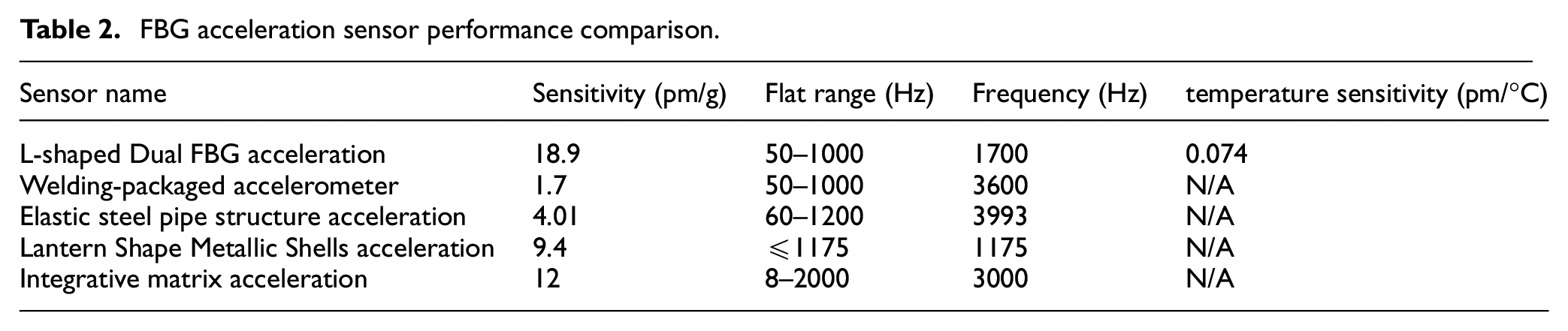
An FBG acceleration sensor based on flexure hinge is proposed in this paper targeting at the problem of low sensitivity of existing FBG acceleration sensor when measuring medium-high-frequency signals. Two FBGs are fixed on L-shaped support in a differential arrangement to improve sensitivity of sensor and reduce adverse effects of temperature changes. Research results show that resonant frequency of sensor is about 1700 Hz and has good linearity in flat range of 50–1000 Hz. Sensitivity of acceleration sensor can reach 18.9 pm/g, transverse anti-interference degree is less than 8.87%, and temperature sensitivity of double FBG after differential operation is only 0.074 pm/°C. As shown in Table 2, Compared with other FBG acceleration sensors, the sensor designed in this paper improves the sensitivity to 18.9 pm/g, further reduces the volume, and has better temperature self compensation ability, but there is still much room for improvement, such as lateral anti-interference capability. As a result, the original scheme can be further improved and be applied to monitoring research in fields like micro seismic crack detection, mechanical equipment operation state and structural health monitoring as soon as possible.
FBG acceleration sensor performance comparison.
Footnotes
Declaration of conflicting interests
The author(s) declared no potential conflicts of interest with respect to the research, authorship, and/or publication of this article.
Funding
The author(s) disclosed receipt of the following financial support for the research, authorship, and/or publication of this article: This study was financially supported by the Self-financing project of scientific research and development plan of Langfang Science and Technology Bureau(Grant Nos. 2018011025, 2020011048), the The National Key Research and Development Programme of China (Grant No. 2019YFC1509504), the Fundamental Research Funds for the Central Universities (Grant No. ZY20215101), the Opening Foundation of Hebei Key Laboratory of Earthquake Dynamics (Grant No. FZ212103).