
Abstract
This article presents an energy management approach for the hybrid energy storage system in an electric bus at different temperatures. An electric bus equipped with a semi-active hybrid energy storage system is considered as the research object. According to the urban climatic characteristics of the vehicle running, the convex optimization approach considering temperature factors is proposed. The purpose of this study is to minimize the energy loss and maximize the discharge and charge depth of the super capacitor. Simulation results show that the comprehensive energy efficiency of the proposed method is 83.31% and the comprehensive energy efficiency is improved by 2.42% at 25°C, which is compared with the rule-based power allocation method based on urban driving cycle in Harbin, China. When the ambient temperature is −5°C, the comprehensive energy efficiency of the proposed method is 81.03%. This result is improved by 1.45% and the battery power variance at −5°C is reduced by 20.11% compared with the rule-based power allocation method. Therefore, the proposed power distribution method can effectively improve the functioning of an electric bus at different temperatures.
Introduction
The functioning of a lithium-ion battery in an electric vehicle is significantly affected by the ambient temperature. With a decrease in the temperature, the ohm resistance, internal resistance, and total internal resistance of the battery will increase. 1 For instance, the charging ohm resistance is five times the normal temperature resistance. When the temperature is below −10°C, the battery will show significant power loss and capacity loss. 2 The functioning of the power battery of an electric vehicle in Harbin, a city in the north of China, changes at different temperatures because the temperature of the city is different in summer and winter. Although the research results demonstrate that the use of an electric vehicle hybrid energy storage system (HESS) could improve the working ability of the electric vehicle and extend the life of the power battery at low temperature, the methods to optimize the size and power split of an HESS are the key technical problems in the application of electric vehicles.3,4
There are several researches in the field of HESS. The HESS energy management strategies can be divided into on-line and off-line. On-line energy management strategies mainly include rule-based energy management strategies, energy management strategies based on model predictions and energy management strategy of fuzzy control.5,6 Off-line energy management strategies mainly includes Pontryagin’s minimum principle, dynamic programming (DP), convex optimization, and other methods. 7 In Song et al., 8 aiming at a semi-active HESS with different structures, a DP method to solve the problem of optimization of semi-active HESS was presented. In Song et al., 9 a new semi-active HESS was proposed, and a DP method to optimize size of the semi-active HESS was used to minimize the operating costs and battery capacity loss. In Hu et al., 10 convex optimization method was used to optimize the size of battery and super capacitor (SC) in a fuel cell hybrid vehicle with a semi-active HESS.
Wang et al. 5 and Azib et al. 11 used a kind of rule-based energy management approach for semi-active HESS. In Garcia et al., 12 the energy management strategy of fuzzy control was used to allocate energy to the HESS. In Romaus et al., 13 stochastic DP was proposed. In Romaus et al., 13 there were two objects whose purpose was to reduce the power loss of the HESS and to ensure that the SC voltage was close to the reference voltage. Torreglosa et al. 14 proposed a model predictive control of the HESS for energy management. In order to reduce the power loss of HESS, Laldin et al., 15 used a prediction algorithm to distribute the power of the storage system. Vinot and Trigui 16 used Pontryagin’s minimum principle to reduce the root mean square value of the battery current. In Moreno et al., 17 a neural network was applied to reduce the power loss. Although the aforementioned power optimization methods can achieve good results under normal temperature or fixed working conditions, the influence of temperature was neglected.
This study is concerned with energy management of semi-active HESS in an electric bus. In this article, a convex approach is proposed combined with the climatic characteristics of Harbin, whose optimization objective is to minimize the energy loss and maximize discharge and charge depth of the SC. The proposed method will realize the efficient and stable operation of HESS at different temperatures.
Analysis of configuration and working modes of HESS
There are three configurations of HESS: passive, fully active, and semi-active. 18
The configuration of a passive composite energy storage system is shown in Figure 1, where an SC and battery are connected in parallel with a drive motor. The SC acts as a low-pass filter to reduce the impact of frequent output power changes on the power batteries. This structure has the characteristics of high efficiency and low cost. However, this parallel approach requires the two energy sources to have the same voltage, thus limiting the use of SCs; moreover, it cannot achieve control of the two energy sources.
Passive parallel configuration.
The configuration of a fully active composite energy storage system is shown in Figure 2. The configuration applies to two chopper circuits. Through the control of the two chopper circuits, the energy distribution of the SC and battery is flexibly realized. However, the structure of the composite energy storage system is relatively complex in terms of control. Moreover, the two chopper circuit structures reduce the system efficiency and increase the costs.

Fully active configuration.
Battery/SC configuration is shown in Figure 3. The battery is connected to the DC bus, via a DC/DC converter, with the SC in parallel. The main feature of this structure is its ease of control, but the SC directly connected to the DC bus causes the problem of bus voltage instability.

Battery/SC configuration.
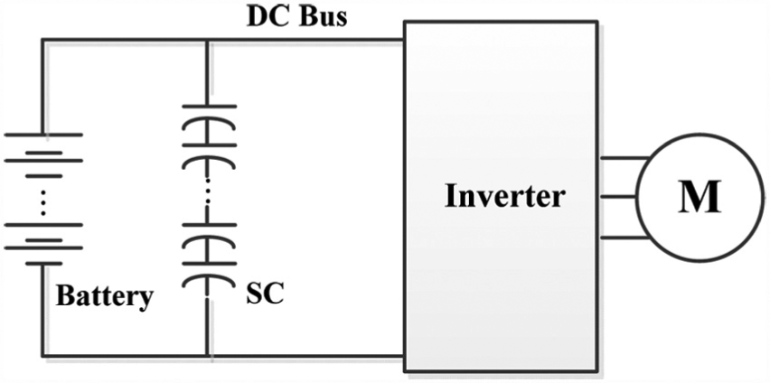
SC/battery configuration is shown in Figure 4. The SC is connected to the DC bus via a bi-directional DC/DC converter. Compared with the fully active composite energy storage system, this structure reduces the costs. Compared with battery/SC configuration, the bus voltages is more stable. Therefore, this study selected this structure as the research object. In general, for such a composite energy storage system, the bi-directional DC/DC converter is turned off when the output power of the power battery can satisfy the power demand of the electric vehicle. When the output power of the power battery is not sufficient to satisfy the requirements of the electric vehicle, the bi-directional DC/DC converter is opened, and the output power of the SC and the battery satisfy the power demand of the electric vehicle. Under braking conditions, the bi-directional DC/DC converter is opened to ensure the use of SC to absorb the feedback energy. When the SC cannot satisfy the feedback energy requirements, the power battery will be used to feedback energy.

SC/battery configuration.
Power system modeling
Traction modeling
When a passenger is traveling on the road, the traction motor should overcome the running resistance (Ft), including the rolling resistance (Ff), air resistance (Fw), slope resistance (Fi), and acceleration resistance (Fj), to satisfy the following equations 19


where f is the rolling resistance coefficient, m is the mass of the electric bus, g is the gravitational acceleration (assumed to be 9.8 m/s 2 ), and α is the slope of the road. In this study, α = 0, Cd is the air resistance coefficient, A is the windward area of the electric vehicle, ρ is the air density, and ua is the motor speed.
According to the pure electric bus power balance characteristics, at time t, the following relationship should be satisfied

where Pm is the output power of the motor, which is equal to the multiplication of Ft and speed v; Pmloss is the loss power of the motor; Paux is the power of the electric air conditioner, electric power steering, and other electric auxiliary systems; Pbt is the output power of the battery port; Psct is the output power of the SC port; and ηdc is the bi-directional DC/DC converter efficiency.
HESS modeling
The SC model is shown in Figure 5, where Rsc is the equivalent series resistance of the SC.

The equivalent model of SC.
The state of charge (SOC) and open circuit voltage of the SC have the following relationship

where usc is the open voltage of the SC, socsc is the SOC of the SC, and usc0 is the open circuit voltage of the SC when its SOC is equal to 0, and its value is 0. Furthermore, b is the amount associated with dusc/dsocsc, and it can be obtained by fitting the data. According to the SC model shown in Figure 5, the following relationship exists

where Psct is the output power of the SC port, Psc is the output power of the SC in the ideal state, and Pscloss is the total power dissipated in the equivalent series resistance of the SC. The SC satisfies the following relationship
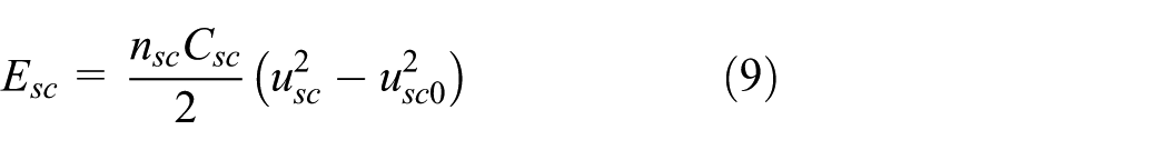
where Esc is the energy of the SC, nsc is the number of SCs, and Csc is the capacitance of the SC. The output power of the SC satisfies the following relationship

where Pnsc is the output power of the SC and isc is the current of the SC. According to equation (10), the single current flowing through the SC is

According to equations (9) and (11), the total power Pscloss that can be dissipated in the equivalent series resistance of the SC satisfies the following equation

where Rsc is the equivalent series resistance of the SC. The relationship between the energy Esc and power Psc of the SC is

The SC single current isc ∈ [Iscmin, Iscmax], where Iscmin is the minimum value of the output current of the SC and Iscmax is the maximum value of the output current of the SC; therefore, the power of the SC Psc satisfies the following equation

The SOC of SC satisfies [SOCscmin, SOCscmax], where SOCscmin is the minimum value of the SOC of the SC and SOCscmax is the maximum value of the SOC of the SC. Hence, the energy of the SC has the following constraints

In order to ensure that the energy of the SC remains the same as its initial value, the following constraints are set

where t0 and tf are the initial time and final time of a cyclic condition, respectively. The battery cell model is shown in Figure 6. In the figure, Rbat is the equivalent series resistance of the battery.
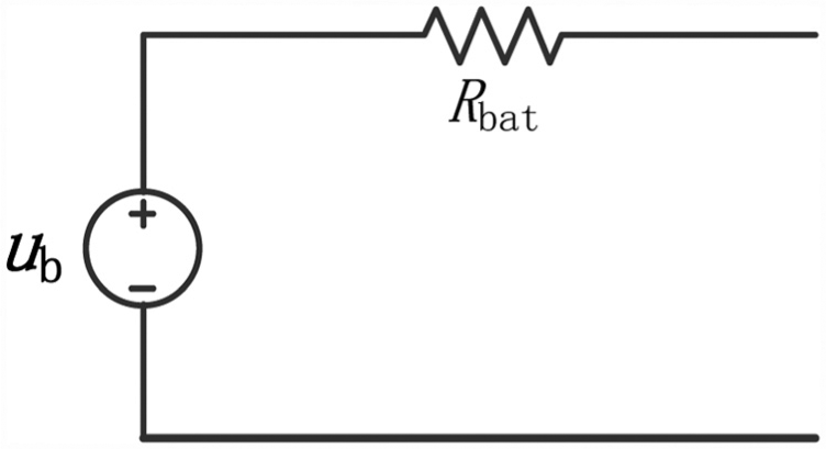
The equivalent model of power battery.
The relationship between the open circuit voltage and the SOC of lithium iron phosphate batteries at different temperatures is shown in Figure 7.

The relationship between SOC and battery open circuit voltage.
From Figure 7, it can be observed that the battery SOC and open circuit voltage can be approximated by the following linear relationship when the SOC is in the range of 10%–100%

where ub is the open circuit voltage of the battery, socb is the SOC of the battery, ub0 is the open circuit voltage when the SOC of the battery is equal to 0, a is the amount associated with dub/dsocb, and ub0 can be obtained by fitting the data.
According to the equivalent model of the power cell in Figure 6, we can observe that the relationship between the power Pb and the power of the port output Pbt is not considered when the equivalent series resistance Rbat is considered

where Pbt is the battery output power, Pb is the ideal state under the conditions of the battery output power, and Pbloss is the loss of power in the battery resistance. The stored energy of the power battery Eb satisfies
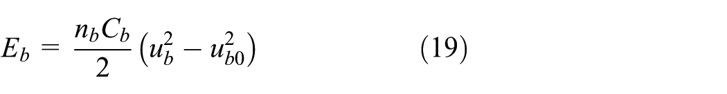
where nb is the number of batteries used, Cb is the capacitance of the battery, ub is the open circuit voltage of the battery, and ub0 is the open circuit voltage when the battery SOC is equal to zero. The output power of the battery cell satisfies the following relationship

where Pnb is the output power of the battery cell and ib is the current of the battery cell. According to equation (20), the battery cell current is

According to equations (19) and (21), the power loss Pbloss in the battery resistance can be obtained as

where Rb is the internal resistance of the battery and Cb is the capacity of the battery. The relationship between the energy Eb and power Pb of the battery is as follows

Owing to the battery cell current ib ∈ [Ibmin, Ibmax], where Ibmin is the minimum value of the output current of the battery cell and Ibmax is the maximum value of the current that the battery cell can output, the battery power Pb satisfies

Owing to the battery SOC∈[SOCbmin, SOCbmax], where SOCbmin is the minimum value of the SOC of the battery and SOCbmax is the maximum value of the SOC of the battery, the battery energy Eb satisfies

Power distribution approach based on convex optimize
Convex optimization is a kind of optimization problem approach where the objective function is a convex function. Compared with the traditional global optimization algorithm, it has the characteristics of fast operation.20–22 The standard form of convex optimization is

where f0, …, fm are convex functions. The equation constraint function

This inequality satisfies the requirement of inequality in the standard form of convex optimization. Similarly, the SC power exists as follows to satisfy the inequality conditions of the convex optimization

Therefore, the constraint condition of the convex optimization problem is as follows

In order to reduce the energy consumption of the electric bus during operation, we accept the factor

where Vmin is 0 and Vmax is the maximum value of the open circuit voltage of the SC. Therefore, the objective function is

where a1 and a2 are the weight values, and they can be selected according to the actual demand. In this study, the values of a1 and a2 are shown in equation (31)

where T is the environment and T0 is the set temperature threshold. In this study, T0 is 0°C.
By the convex optimization method, the basic flow of the energy distribution of the HESS of the electric vehicle is shown in Figure 8.

Power allocation process of the power source.
Simulation results
In order to verify the validity of the method proposed in this article, an electric bus with a HESS is considered as the research object, as shown in Table 1. Furthermore, the bus road conditions of Harbin city are selected as the cycle conditions, as shown in Figure 9. 24 In Figure 9, Pdem is power demand under the bus road conditions of Harbin city. Under the conditions of −5°C and 25°C, the optimal power distribution of the power battery and the SC of the electric bus with the composite energy storage system was determined by the convex optimization method. Moreover, the results of the optimal allocation are compared with the rule-based power allocation method proposed in Peng et al. 25
Parameters of electric vehicle with semi-active HESS.

HESS: hybrid energy storage system; SC: super capacitor.

Harbin city driving cycle.
The rule-based power allocation strategy, which is compared with the method presented in this article, is shown in Figure 10. When the electric bus functions in the driving mode, the output power Pb of the power battery and the output power Psc of the SC can be expressed as equation (32)
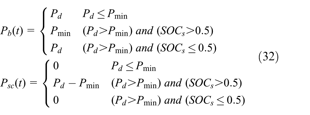
where SOCs are the SOCs of SC, Pd is the power demand under this condition, and Pmin is the power threshold.

Rule-based optimization method.
According to the rule-based power allocation strategy described in Figure 10, when the pure electric bus is in the braking state, that is, Pd < 0, the output power of the power battery Pb and the output power of the SC Psc can be expressed as equation (33)
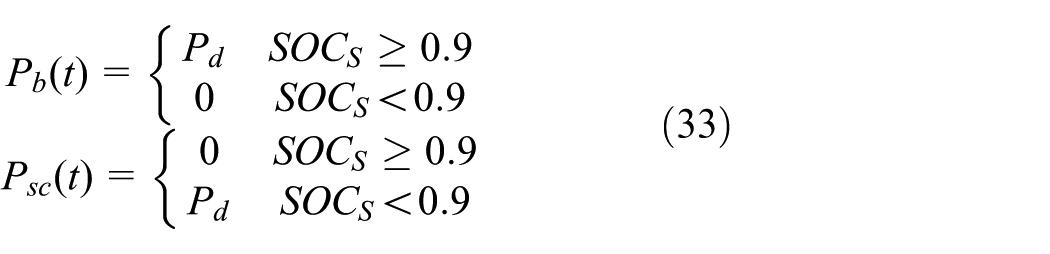
where SOCs are the SOCs of SC and Pd is the power demand under this condition.
The results of the power distribution of the SC and the power battery are shown in Figures 11 and 12, where bottom image is an enlarged view of the red box, in the case of 25°C and −5°C, respectively. It can be observed from Figure 11 that, at the ambient temperature of 25°C, the maximum output power of the power battery is 80.47 kW and that of the SC is 80.49 kW. Thus, SC can effectively achieve power balance. From Figure 12, at the ambient temperature of −5°C, the maximum output power of the battery is 73.58 kW and that of the SC is 87.47 kW. The output power of the SC is improved relative to the optimization result in Figure 11. Because, at low-temperature conditions, the optimization method highlights the utilization of SC in terms of providing power.

Power distribution of battery and super capacitor at 25°C.

Power distribution of battery and super capacitor at −5°C.
The power allocation strategy based on the rule is shown in Figure 13 where bottom image is an enlarged view of the red box. The comparison of the SC power and the battery distribution power between the two strategies is shown in Figure 14. From Figure 14, when Pd < 0, the power allocation method proposed in this article is more effective than the rule-based power allocation strategy, and the use of SC achieves a balance of power and optimizes the functioning of the battery at −5°C. Therefore, the proposed method of power distribution at −5°C can effectively extend the life of the battery.

Rule-based allocation power.

The comparison of the two strategies.
In order to compare the optimization effect of the power allocation strategy, according to Hu et al., 26 the calculation method of the comprehensive energy efficiency of the electric vehicle is shown in equation (34)

where η is the comprehensive energy efficiency of the electric vehicle, Ed is the energy output of the electric vehicle under a working condition cycle, and Eele is the electric energy consumed in a working cycle. Ed and Eele are calculated as shown in equation (35)
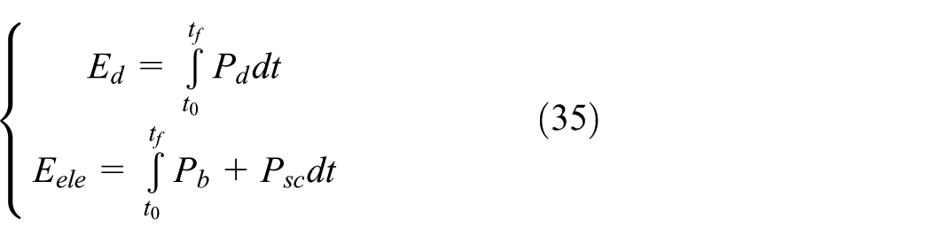
where t0 is the initial time of the operating condition, tf is the end time of the operating condition, Pd is the power demand of the electric bus under this condition, Pb is the output power of the power battery in the HESS, and Psc is the output power of the SC.
According to the calculation results of Figures 12–14, the comprehensive energy efficiency of HESS under different temperature conditions can be obtained by combining the calculations of equations (34) and (35) as shown in Figure 15.

Comprehensive energy efficiency of composite energy storage systems under different temperature conditions.
It can be observed from Figure 15 that the comprehensive energy efficiencies of the convex optimization and the rule-based power allocation method are 83.31% and 80.89% at 25°C, respectively. Compared with the rule-based power allocation method, the energy efficiency of the proposed power allocation method is improved by 2.42%. When the temperature is −5°C, the comprehensive energy efficiencies of the convex optimization and the rule-based power allocation method are 81.03% and 79.58%, respectively. At −5°C, compared with the rule-based power allocation method, the energy efficiency of the proposed power allocation method increased by 1.45%.
The energy flow diagram of the power system is shown in Figures 16 and 17 with the convex optimization method and the rule-based power distribution method at 25°C and −5°C, respectively. In the electric vehicle running process, power loss mainly contains the SC loss, battery loss, motor loss, and bi-directional DC/DC loss. From Figures 16 and 17, compared to the rule-based power allocation method, the battery power loss of the convex optimization allocation strategy in the ambient temperature of 25°C and −5°C are reduced by 27.3% and 19.25%, respectively. Although the SC loss is relatively increased, the functioning of the battery is optimized. The power system achieves a reduction in the comprehensive energy consumption.
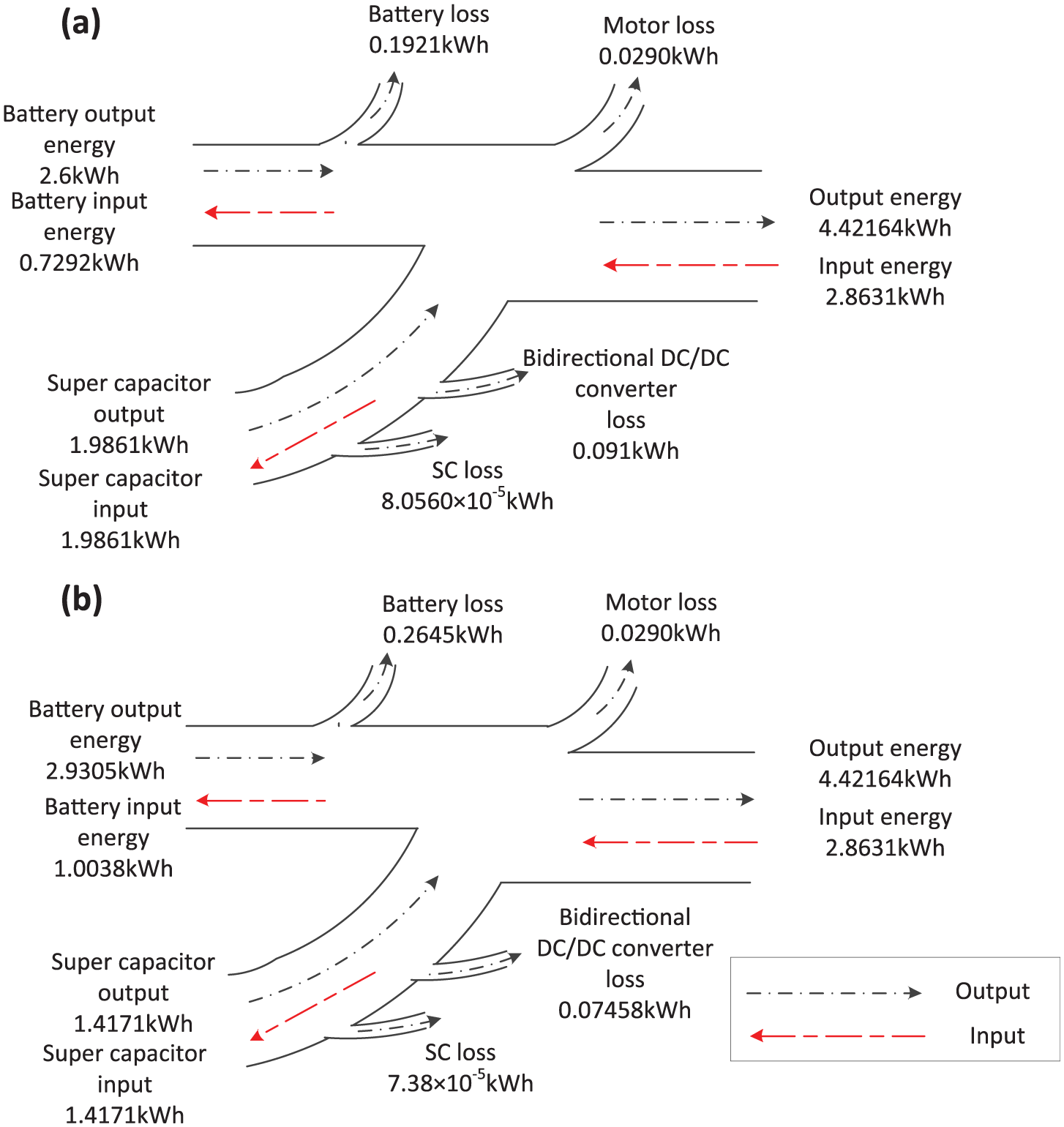
At 25°C, energy flow diagram of the two power distribution methods: (a) power allocation method based on convex optimization and (b) power allocation method based on rule.
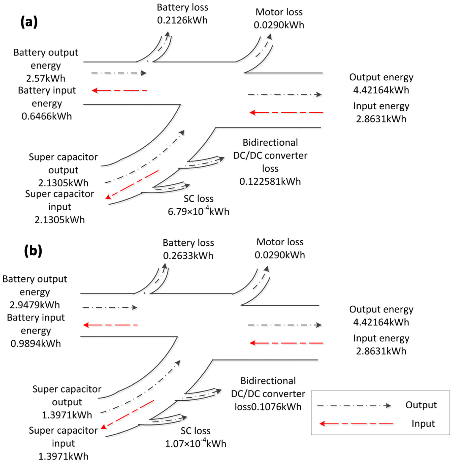
At −5°C, energy flow diagram of the two power distribution methods: (a) power allocation method based on convex optimization and (b) power allocation method based on rule.
In some studies,27–29 the increase (or decrease) in the battery power amplitude and variance can lead to an increase (or decrease) in the battery life attenuation. For the optimal power distribution at −5°C, according to the method of evaluation of the energy management strategy in Choi et al., 30 combined with equation (36), the mean square error s of the battery power is calculated as

where s is the mean square deviation of the battery power, Pb(t) is the battery power at time t, Pavg is the average of the battery power at each time, t0 is the initial time of a condition, and tf is the termination time of a condition. According to the aforementioned mean square error calculation method, the mean square errors of the proposed method and the rule-based method at −5°C are obtained, as shown in Figure 18.

Comparison of the mean square error of the battery power.
As evident from Figure 18, the mean square error of the battery power based on the convex-optimized power distribution method is 8.66 kW. Compared with the rule-based power allocation strategy, the battery power variance is reduced by 20.11%. The main reason for this result is that, at low temperatures, the proposed optimization method is more focused on the use of SCs to reduce the frequent changes in the power the battery.
The comparison of the power allocation method and the rule-based power allocation method is shown in Table 2. According to the results in Table 2, the maximum output power of the battery in the proposed power distribution method is 80.47 and 73.58 kW at 25°C and −5°C, respectively. Compared with the rule-based power distribution method, the maximum output power of the power battery is reduced by 46.00% and 50.62 %, respectively. Therefore, the proposed power distribution method effectively reduces the capacity loss of the power battery.
Simulation results.
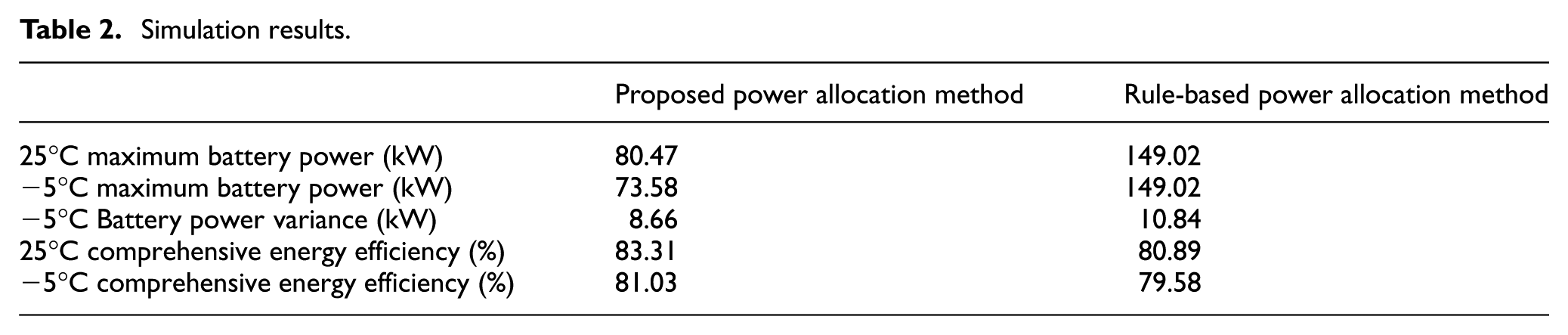
It can be observed from the simulation and analysis results that the proposed power distribution method can effectively extend the life of the power battery of an electric vehicle under low-temperature conditions. Simultaneously, the power distribution method proposed at −5°C and 25°C effectively increases the comprehensive energy efficiency of the electric vehicle. According to the above analysis, the power allocation method based on convex optimization improves the running characteristics of electric vehicles under different temperature conditions.
Conclusion
In this article, an electric bus system equipped with a semi-active composite energy storage system is considered as the object of study. Combined with the urban climate status at the area where the vehicle operates, the minimum energy consumption of the power system and the maximum discharge and charge depth of the SC are considered as the optimization targets. A convex optimization approach considering the influence of temperature is proposed, which realizes the optimization of the working conditions of the electric bus HESS under different ambient temperature conditions. The urban driving cycles in Harbin are considered as the cyclic conditions, and the approach was compared with the rule-based power distribution method at 25°C and −5°C. The simulation results show that the comprehensive energy efficiency of the dynamic system is 83.31% at 25°C, and compared with the rule-based power allocation method, the energy efficiency is improved by 2.42%. When the ambient temperature is −5°C, the comprehensive energy efficiency of the power system is 81.03%, and the comprehensive energy efficiency is improved by 1.45% compared with the rule-based power allocation method. The proposed method effectively improves the comprehensive energy efficiency of the electric vehicle integrated with an energy storage system at different temperatures. At 25°C and −5°C, under the premise of satisfying the vehicle power demand, the maximum output power of the proposed power distribution method is 80.47 and 73.58 kW, respectively. Compared with the rule-based power distribution method, the maximum output power of the power battery is reduced by 46.00% and 50.62%, respectively. The battery power variance is reduced by 20.11%. The proposed power distribution method effectively prolongs the service life of the battery and effectively improves the functioning of the electric bus HESS at different temperatures.
Footnotes
Handling Editor: Hamid Reza Karimi
Declaration of conflicting interests
The author(s) declared no potential conflicts of interest with respect to the research, authorship, and/or publication of this article.
Funding
The author(s) disclosed receipt of the following financial support for the research, authorship, and/or publication of this article: This work was supported by the State Key Laboratory of Automotive Safety and Energy under Project No. KF16062 and Natural Science Foundation of Heilongjiang Province, No. E201451.