
Abstract
The battery/supercapacitor (SC) hybrid energy storage system (HESS) is widely applied in electric vehicles (EVs) in recent years due to the hybrid system which combines the benefits of both devices. This paper proposes an adaptive power distribution scheme for battery/SC HESS to maximise the usage of SC according to its stored energy and load current. In the approach, the low-pass filter is developed with adaptive algorithm to calculate the suitable cut-off frequency to allocate the power demand between the battery and SC. The approach can adjust the cut-off frequency but not change the structure of the control system, and thus its original property of simple implementation and stability is not affected. The comprehensive simulation study verifies the effectiveness of the proposed adaptive power distribution scheme in a battery/SC HESS and its stability is further validated using Lyapunov method. The result shows that the adaptive method performs better than a traditional control system with 20%–40% less battery energy throughput during operation and can adjust the dynamic response of the HESS according to the energy capacity of SC to further improve system efficiency. The proposed adaptive power distribution scheme is verified able to extend the service life of the HESS system in EV applications.
Keywords
Introduction
Among energy storage devices, Li-ion batteries and supercapacitors (SCs) are the two most rapidly developing technologies of energy storage devices (Allegre et al., 2009; Khalid, 2019; Singh and Lather, 2021). As the two most commonly used energy storage devices, Li-ion batteries and SC have their own advantages and disadvantages. Li-ion batteries have higher energy capacity but lower power density and a component life in the order of thousands of lifecycles (Li and Joos, 2008). The lifecycle of a battery can be affected by ageing mechanisms coupled with various factors, such as battery manufacturing, operations, and environmental conditions (Liu et al., 2022b). After numerous times of charge/discharge cycles, the battery performance will be inevitably degraded, which will greatly limit the operating time and service life of energy storage systems (ESSs). Compared with the battery, SCs have a higher power density and tolerates more than 1 million charge/discharge cycles (Navarro et al., 2021; Yang et al., 2020). In addition, Li-ion batteries have higher discharge efficiency than other batteries, but the rate capacity effect reduces the discharge efficiency when the load current increases. In contrast, SCs have extremely low internal resistance and higher discharge efficiency (Allegre et al., 2009). In the application of electric vehicles (EVs), batteries are usually the most widely applied energy source to provide and store electrical energy (Camara et al., 2011; Golchoubian and Azad, 2017; Song et al., 2017, 2018; Yodwong et al., 2020; Zhang et al., 2017). As battery has limited numbers of fully charge/discharge cycles in its service life, if the battery is the only energy source in the ESS, its cumulative depth of discharge (DOD) will increase rapidly to balance the power requirements of the load. However, SC cannot be used as a main energy storage device to provide energy for a long period of use due to its property of low energy density and high self-discharge rate. To solve this issue, researchers have been developing hybrid energy storage systems (HESSs), which combine the benefits of high-power density devices and high-energy density devices, such as batteries and SCs, or the use of mixed energy and power batteries in a single pack. The HESS of batteries and SCs becomes a typical solution to provide high energy capacity and high power density (Dogger et al., 2010). A method to determine whether the energy storage unit should consist of only batteries, only SC, or a combination of the two was first proposed (Schupbach et al., 2003). After that, the general usage trends of batteries and SCs and some important concepts for device comparison were proposed (Du Pasquier et al., 2003). In addition to applications in EVs, in the context of the vigorous development of renewable energy in recent years, researchers have found that the combination of photovoltaic and wind energy increases the severity of power fluctuations, which adversely affects the longevity and scale of traditional energy storage methods (Ravada et al., 2021). To absorb as much as possible the power exchange generated by the intermittency of renewable energy and sudden changes in load demand, SC-based HESSs are also widely used in wind/photovoltaic power generation (Abdelkader et al., 2018; Elmorshedy et al., 2021; Jing et al., 2018; Li et al., 2009; Tummuru et al., 2014) and microgrid technologies (Enang and Johnson, 2020; Jing et al., 2016; Ren et al., 2020; Thounthong et al., 2007). In addition, HESS is also widely used in railways (Han et al., 2017; Li et al., 2017), fuel cell ships (Chen et al., 2020), and other types of renewable energy sources (Jayasinghe et al., 2011).
In practice, the uncertain power flow is the main reason to affect the efficiency and performance of HESS. Due to this, an effective strategy is needed for power management to allocate power output of batteries and SCs. In 2011, the battery/SC-based HESS energy management solution was first mathematically formulated as an optimisation problem (Choi et al., 2011). Afterwards, researchers discussed the optimisation goals of improving overall drive efficiency and extending battery life (Carter and Cruden, 2008; Carter et al., 2012). The main goal of optimisation is to extend battery life and reduce unnecessary battery charging/discharging cycles. Therefore, if the charge/discharge rate of the battery and the SC can be modelled and predicted, the size and quantity of the battery and the SC can be further determined more appropriately based on this design to reduce the mass, volume, and costs. A power control framework for calculating the SC reference voltage in consideration of load dynamics while minimising the size/fluctuation of battery power flow is proposed (Choi et al., 2014). In EV applications, the main uncertain power flow is happened during vehicle acceleration and regenerative braking. To absorb the instantaneous and large amount of charging current during the regenerative braking process of EVs, one of the most popular approaches is filter-based HESS that diverges the high-frequency power variations to the SC (Abeywardana et al., 2016), and an optimal energy management control scheme with H-infinity current controller is proposed (Long et al., 2014). The frequency-varying filter is used according to different driving cycles of urban mode or highway mode (Xiaoliang et al., 2013, 2014). In addition, many researchers have developed intelligent methods to perform adaptive energy management for HESS, such as fuzzy logic-based energy management strategies (Herrera et al., 2016) and the use of artificial neural network methods to achieve EV braking power allocation (Naseri et al., 2016). The methods mentioned above analyse and count the historical load and optimise the battery and SC usage in HESS energy storage according to the highest load. In practical applications, the load will not always remain at the highest level, and most of the time, it will be lower than the highest load value. The methods did not take the full advantage of SC to support the battery with its super high cycle life. Moreover, most battery/SC cooperation approaches are designed using rule-based methods (Cao and Emadi, 2011), which is not in continuous operation for improving the performance of power flow and system efficiency. Currently, dividing the load into high-frequency and low-frequency parts by a low-pass filter (LPF) and assigning the optimal current reference to the battery and SC are still the main control logics for the HESS (Arunkumar et al., 2021; Khan and Khalid, 2021). Its advantages are small computational complexity, low control complexity, good robustness, and easy implementation. However, it also has the disadvantages of relatively rigid strategy, only guaranteeing performance under design conditions, and lack of adaptability to changes in load conditions (Xu and Shen, 2021). Therefore, it is necessary to develop a simple and robust method for online, adjusting the usage of battery and SC according to the actual load.
This paper develops a simple structure power distribution scheme using an adaptive frequency power filter to reduce the battery energy throughput and improve the service life of the battery while ensuring the simplicity and stability of the control system. The fixed cut-off frequency in the LPF is replaced with an adaptive algorithm to adaptively improve the utilisation of SC and optimise battery usage. The proposed adaptive filter can calculate the most suitable cut-off frequency according to the stored energy of SC and the real-time load power and uses this to allocate the power generation or recovery of the battery and the SC. This method can maximise the usage of SC in any load strength, so it can be applied to any HESS systems with flexible battery and SC ratio. Moreover, the structure and stability of the control system are not affected and thus it is robust to unpredictable loads with no additional requirements. With minimal changes on the cut-off frequency, the overall service life of the HESS system is effectively improved.
The remainder of this paper is structured as follows. Section ‘Architecture and model of hybrid energy system’ presents the architecture and dynamic model of HESS including the model of Li-ion battery, SC, and bidirectional DC/DC converter. Section ‘Adaptive power distribution scheme with current controller’ presents the adaptive power distribution scheme including the converter current control and adaptive power distribution algorithm, followed by the stability proof of the closed-loop system using Lyapunov function. Section ‘Simulation results’ shows the verification results of the proposed adaptive power distribution scheme in simulation. Section ‘Discussion and future works’ discussed the main findings and drawbacks, and future work. Finally, the paper concludes in section ‘Conclusion’.
Architecture and model of hybrid energy system
Architecture of hybrid energy system in EV
This paper aims to design a controller for battery/SC HESS in EV applications, as its architecture is shown in Figure 1. In the architecture, the SC is coupled to the high voltage bus to drive the electric motor as an energy buffer between the Li-ion battery and load. This is to protect the battery service life to avoid over-current/voltage and maximise the usage of SC.
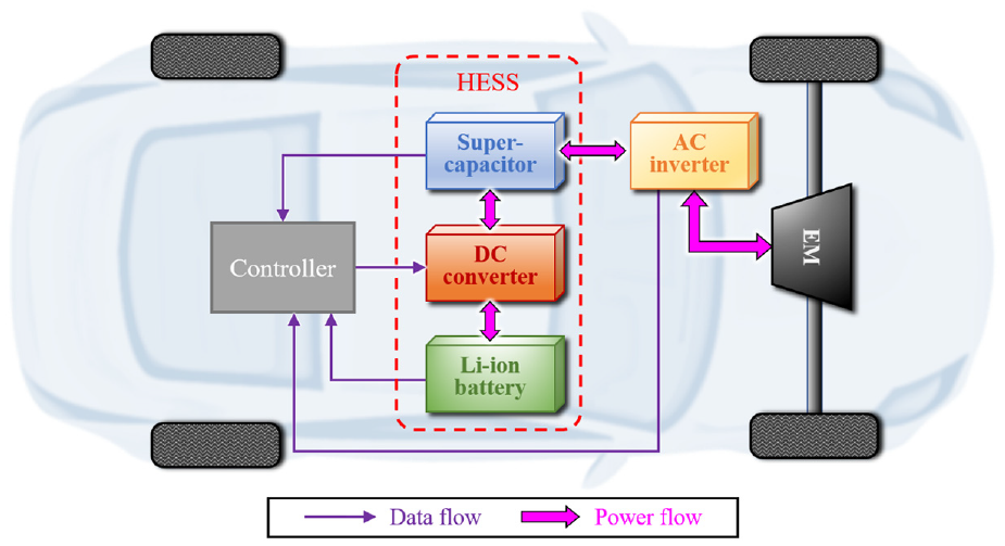
The power source system of EV using HESS.
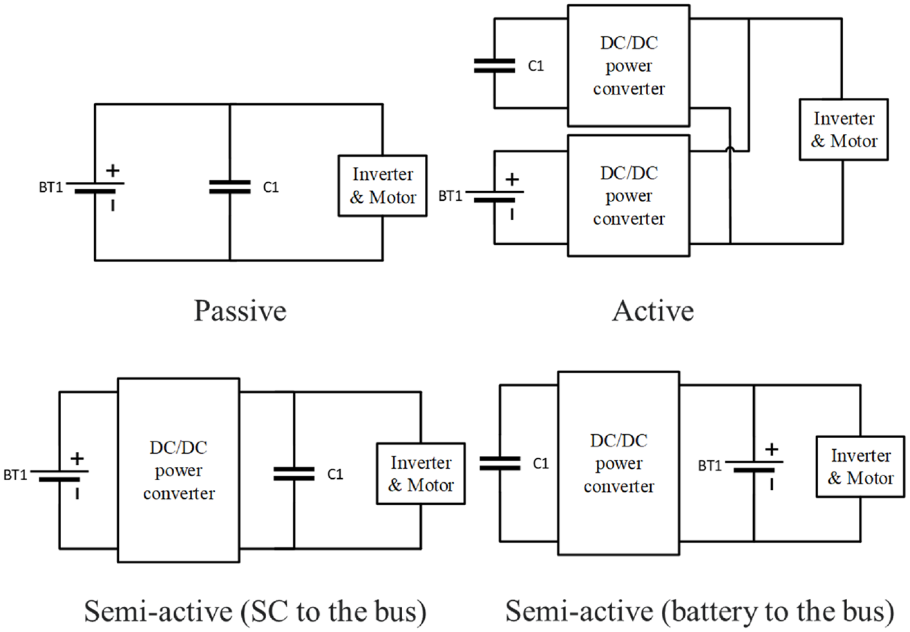
The topologies of the battery/SC hybrid system mainly include passive, semi-active, and active approaches (Choi et al., 2011), as shown in Figure 2. The passive topology is the cheapest and simplest structure but will limit the performance of SC. In the semi-active topology, one of the two energy storage devices is controlled by the half-bridge DC converter and the other is coupled with the bus voltage passively. The fully active topology uses two sets of DC converters to control the power output of the battery and SC separately. The fully active topology has higher costs on converters and more complexity in its control system (Camara et al., 2008, 2009, 2011).
Comparison between switching model and time average model.
Considering the cost and bus voltage maintenance, the semi-active topology is used in this paper for the following design. In battery/SC HESS, the battery is normally coupled with the bus as its terminal voltage and has relatively smaller changes (Allegre et al., 2009). However, using this topology, the high-frequency power provided by SC will be controlled by the DC converter and thus the SC cannot be performed as an energy/power buffer between battery and load. In addition, the frequent usage of DC converter will increase the conduction loss and decrease the overall system efficiency. This paper focuses on the semi-active topology that uses the SC to couple the bus between load and battery. The DC converter is controlled to transfer low-frequency current from battery to SC.
Li-ion battery model
In recent decades, with the popularity of Li-ion battery, the modelling of battery has been widely researched. In this paper, the equivalent circuit model (ECM) is used in the plant model of the HESS. The terminal voltage of a battery is presented from the second-order Thevenin battery model, which includes two resistor–capacitor (RC) parallel branches and an Ohmic resistance.
The ideal battery model is used to present the open-circuit voltage (OCV)

where
The parameters of the second-order ECM,
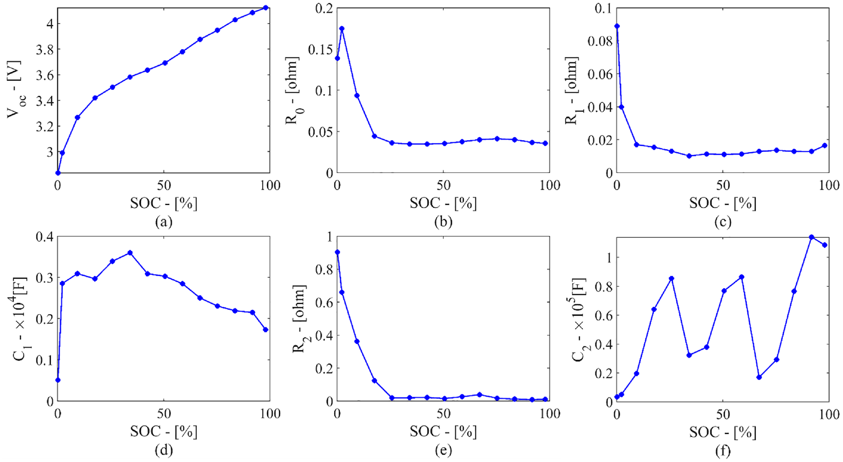
Second-order ECM battery model parameters: (a)
SC unit model
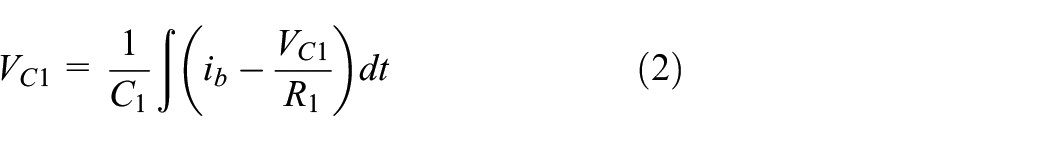
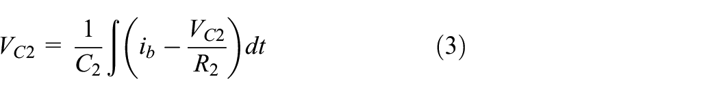
As the electrical behaviour of SC is similar with that of a capacitor, its main components are a fixed value ideal capacitor
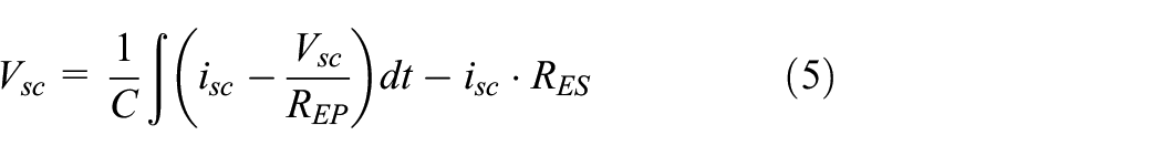
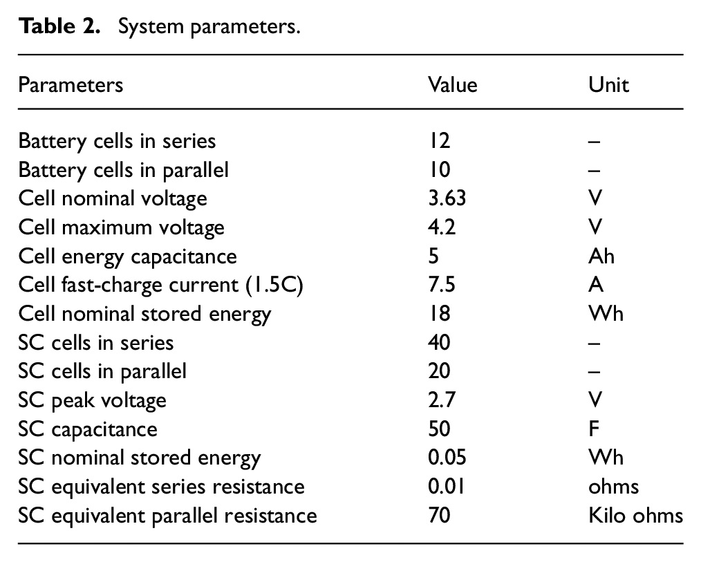
Then it is required to calibrate the parameter. However, the manufacturer only provides the parameter of the capacitance and the internal resistance in series. The parallel resistance of SC can be calculated from its self-discharge rate, which is provided by the manufacturer. Parameterisation of the SC model is defined in Table 2 below.
Model of DC/DC converter
To look into the details of DC/DC converter, the model of each device in the converter is considered. As the bidirectional DC/DC converter is half-H bridge, its voltage is limited by that one side should be higher than another side. If reverse, the converter will lose its functionality. For example, the voltage on the left side (V1) is higher than that on the right side (V2). The full-H bridge converter solved this problem by combining them together to share the inductor between them. However, the full-H bridge costs more and is more complex in switching control (four switches should be coordinated). In practice, the half-H bridge bidirectional converter is more commonly used (Guidi et al., 2007a, 2007b). In HESS application, the battery voltage variation is relative less than that of SC. Thus, one can manage the size of battery and SC to ensure they satisfy the voltage restriction of DC converter. In the full-H bridge bidirectional converter, it can operate in Buck mode or Boost mode by controlling the ON/OFF of S1 and S2, as shown in Figure 4.
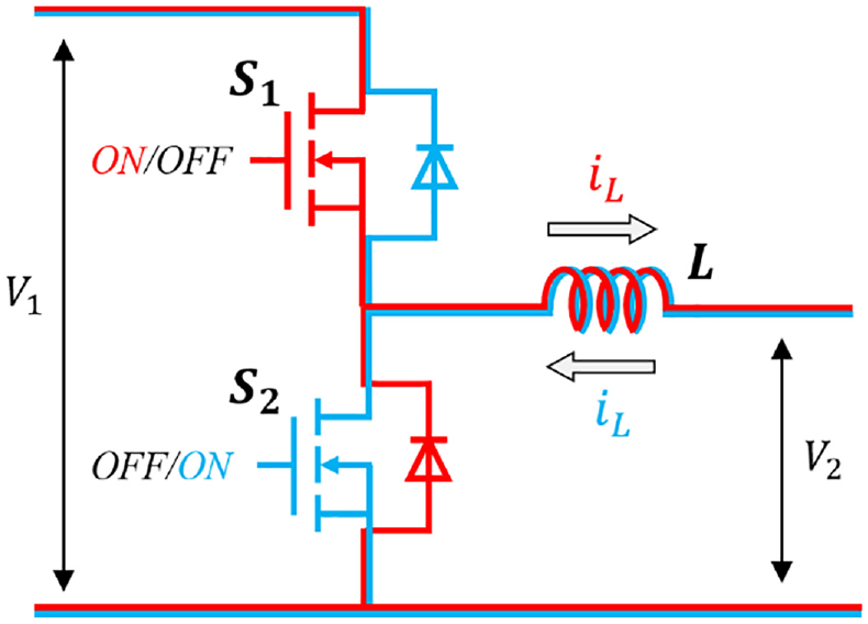
Control mode of bidirectional DC/DC converter.
Power loss model of DC converter
The previous model of the DC converter is simple and ideal. In reality, the efficiency of the converter should be considered in the HESS application. The losses on the DC converter include the switching losses and conduction losses. The conduction loss of MOSFET/diode components can be presented with a switched circuit source between conduction resistor
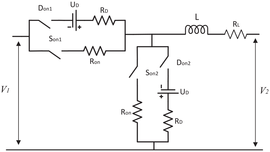
Power loss model of bidirectional DC/DC converter.
In Buck mode, the current flows from the high voltage side to low voltage side. When the switch 1 is ON, the current flow from V1 to V2 through the conduction resistance Ron and inductor L. In this process, the inductor current is increased. When the switch 1 is OFF, the diode D1 stops current flow between V1 and V2. Then the current in inductor will flow through diode D2 and inductor L and back to V2. In this process, the inductor current is decreased.
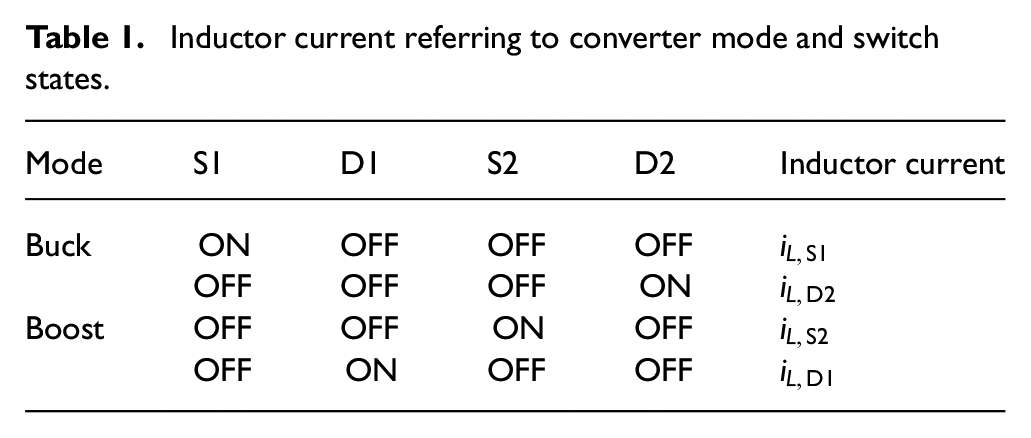
In Boost mode, the current is flowing from low voltage to high voltage side, in the opposite current direction of Buck mode. When the switch S2 is ON, diode D1 stops the current flow into V1. The current is therefore flowing from V2 through the inductor L and conduction resistance Ron and back to V2. In this process, the inductor current is increased. When the switch S2 is OFF, the voltage at the middle point increased to conduct the diode D1. Then the current flow from V2 to V1 through inductor L and diode D1. The relationship between inductor current with converter mode and switch state can be presented as in Table 1. In addition, the inductor current under different conditions is shown as follows
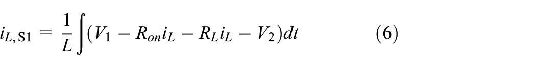
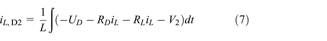
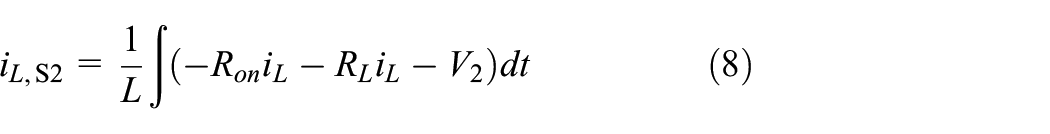
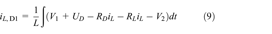
Inductor current referring to converter mode and switch states.
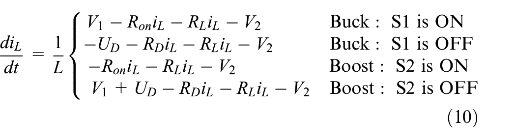
Combining the converter mode and switch states together, the inductor current is presented as
Adaptive power distribution scheme with current controller
Converter duty cycle control
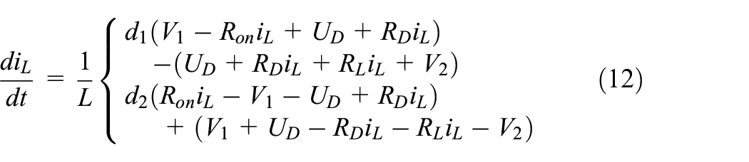
The converter model is in discontinuous switching signal, which is close to reality but the high-frequency switching signal is difficult to use in controller design. The first step is to represent the converter model by replacing the switching model with a time average model. In the time average model defined in Bose (2002), the average current is calculated by the on and off current with duty cycle. This is to simplify the switching behaviour in the converter and thus to reduce the computational frequency of the controller. The time average model of the converter inductor current is presented as
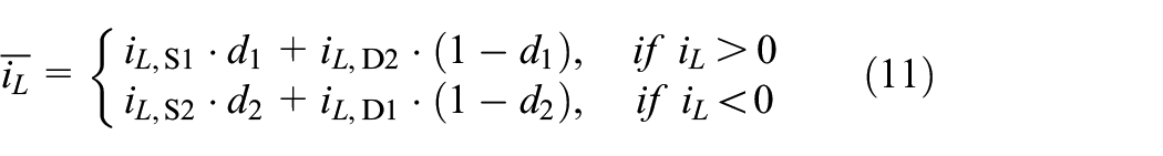
where
Combining equations (11) with (10), the inductor current can be represented as
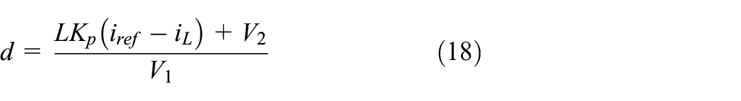
Define the linear control law to the converter system as
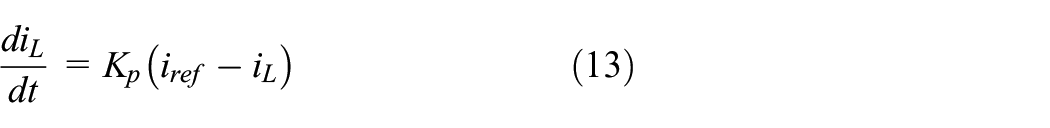
where
Then the duty cycle of switches can be set as
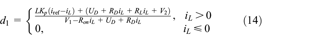
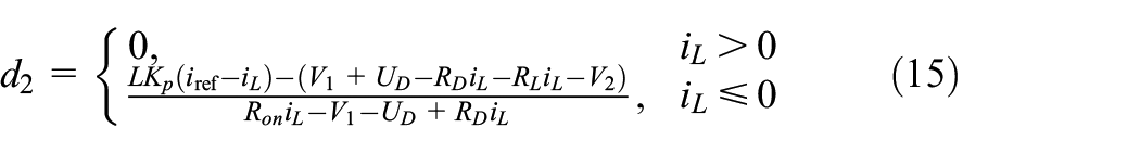
The power loss due to conduction resistance of MOSFET switch, diode, and inductor has much smaller effect than terminal voltage. To simplify the equation, the duty cycle (equations (14) and (15)) can be represented as

where
where
Proper design of the underlying controller is important for tracking the current reference. Control gain can be calculated by some linear control law, such as pole placement. However, pre-designed control gains may not perform well due to uncertain parameters, unmodeled dynamics, and complex interactions between different components of the HESS. In practical study, the control gain still needs to be tuned according to the working conditions. Therefore, the control gain used in this paper is manually tuned considering the target dynamic response of the system in simulation, so that the battery current can track the reference current well.
Adaptive cut-off frequency
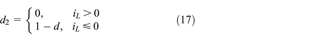
In the semi-active topology, one of the energy storage devices is controlled by the DC converter and the other is uncontrolled to maintain the bus voltage passively. For example, in the topology that SC is connected to the bus, the battery is active while SC is passive connected to the load. The discharge current of the battery is controlled by the DC converter with adjusting the duty cycles,
In the HESS, battery is designed to provide the steady-state or slow-varying power while SC is designed to sink and source the transient power. The power distribution-based coordinated control method aims to split the power demand to steady power and transient power. It can be achieved by filter-based method or Fourier transform to analyse the power demand in the frequency or spectrum. Thus, an LPF is commonly used in the controller design to slip power demand based on their frequency. The main factor to be considered while designing the LPF is the cut-off frequency, which is defined as the maximum frequency an SC will support to the load (Ravada et al., 2021). The blocks of control system and plant of the HESS are shown in Figure 6.
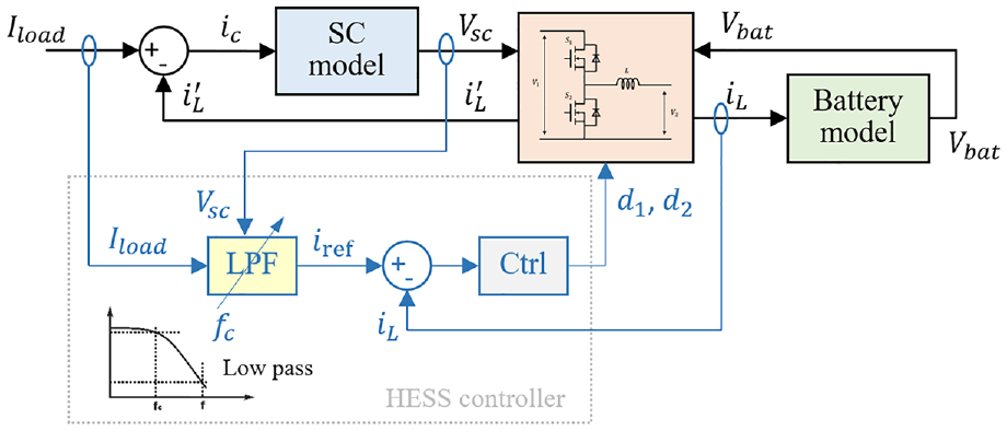
Model and control blocks of hybrid power system.
The LPF can be set as a first-order filter in the Laplace transformation format of

The expected current from battery to SC through the DC converter can be obtained as the load current passing the LPF as

To find its time-dependent dynamics, equation (20) can be represented as
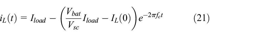
The current difference between the load and battery is supported by the SC. The input current and terminal voltage of SC are presented as

Combining equations (21)–(23), the time-dependent dynamics of SC terminal voltage can be presented as
Its steady-state voltage can be obtained from equation (24) as
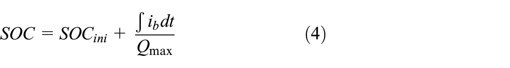
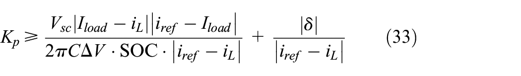
The controller design aims to keep the terminal voltage of SC remained in its limit. The SOC of SC can be defined as
Then the steady-state voltage in equation (25) should be controlled within the range from
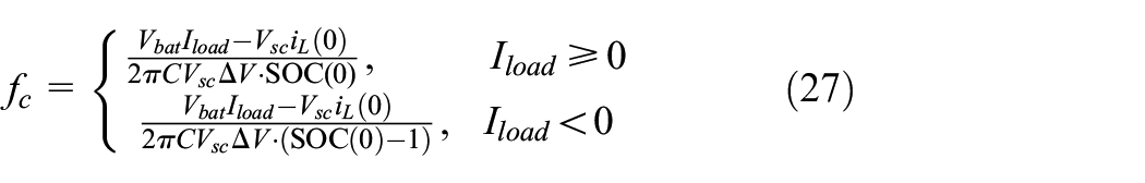
The adaptive cut-off frequency referring the load current and SC SOC is presented as a control surface shown in Figure 7. The map of optimal cut-off frequency to load current and SOC of SC is obtained from equation (27).
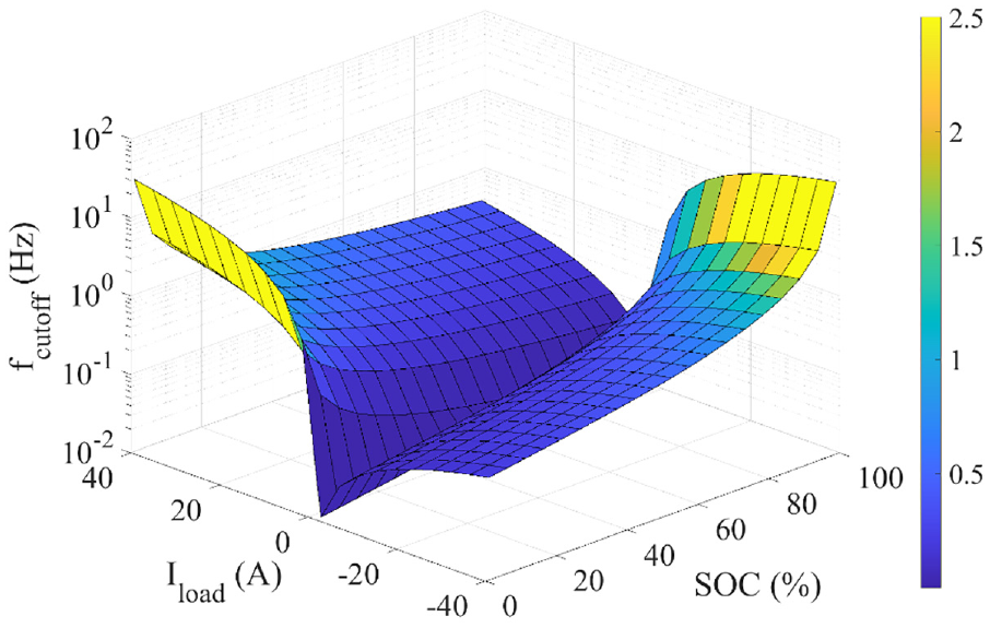
Map of optimal cut-off frequency to load current and SC SOC.
When the load changes its current direction, for example, from discharging to charging the HESS, the battery will also need to change the current direction. Otherwise, the SC will absorb both power from load and power from the battery. Under this condition, the cut-off frequency is set to its maximum value by the controller to reduce the battery current to zero as quickly as possible whatever it is charging or discharging. This both reduces the unnecessary energy throughput of battery and releases the stress of SC to generate power only to the load.
Stability analysis
After the design, the adaptive cut-off frequency approach needs to be proved to ensure the numerical stability of the close-loop system. Combining equations (12) and (16)–(18) together, the battery current output dynamics can be represented as

where
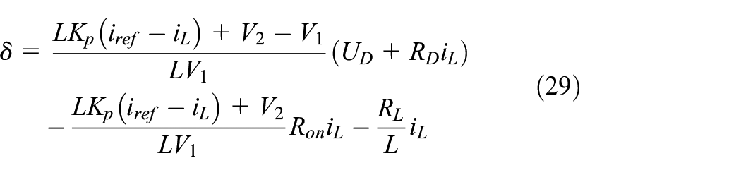
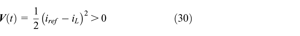
The Lyapunov method is the most widely used mathematical approach to verify the stability of the control system. From equations (28) and (29), the Lyapunov function of current regulation error can be defined as
The derivative of Lyapunov function can be represented as
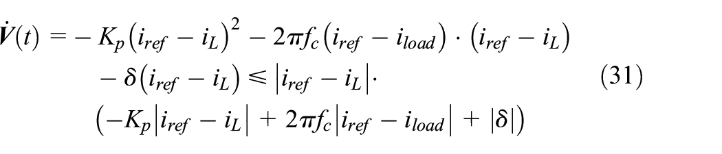
If there exists a

Combining equations (32) with (27), it can be rewritten as
Then it can prove that

The stability of the close-loop system can be guaranteed with the Lyapunov method.
Simulation results
The designed power distribution scheme with adaptive cut-off frequency algorithm is tested in simulation studies using MATLAB/Simulink. The simulation test aims to verify the effectiveness of the proposed adaptive algorithm and comparing its performance with the traditional LPF with fixed cut-off frequency. To make a fair comparison, the two approaches with fixed frequency and adaptive frequency using the same control structure for their target HESS systems that have the same system parameters. The basic system parameters are given in Table 2. The parameters of internal resistance and capacitance of Li-ion battery are using a look-up table from the test results in previous work (Bui et al., 2019). The control gain,
System parameters.
Step-changed current load
The first case is to test the performance of the adaptive cut-off frequency-based coordinated controller under step change in load current. The cut-off frequency setting is different referring to the initial voltage of SC in the HESS. Figure 8 shows the result of the SOC variation of SC and corresponding battery current response under the same load current. From the result, it is clear to find that the higher the SC SOC, the slower the battery current in response. This shows that when the available energy in the SC is high, the battery current responds slower. With the SC used as an energy buffer between battery and load, the battery current response speed is adaptively adjusted by the cut-off frequency to maximise the usage of SC.
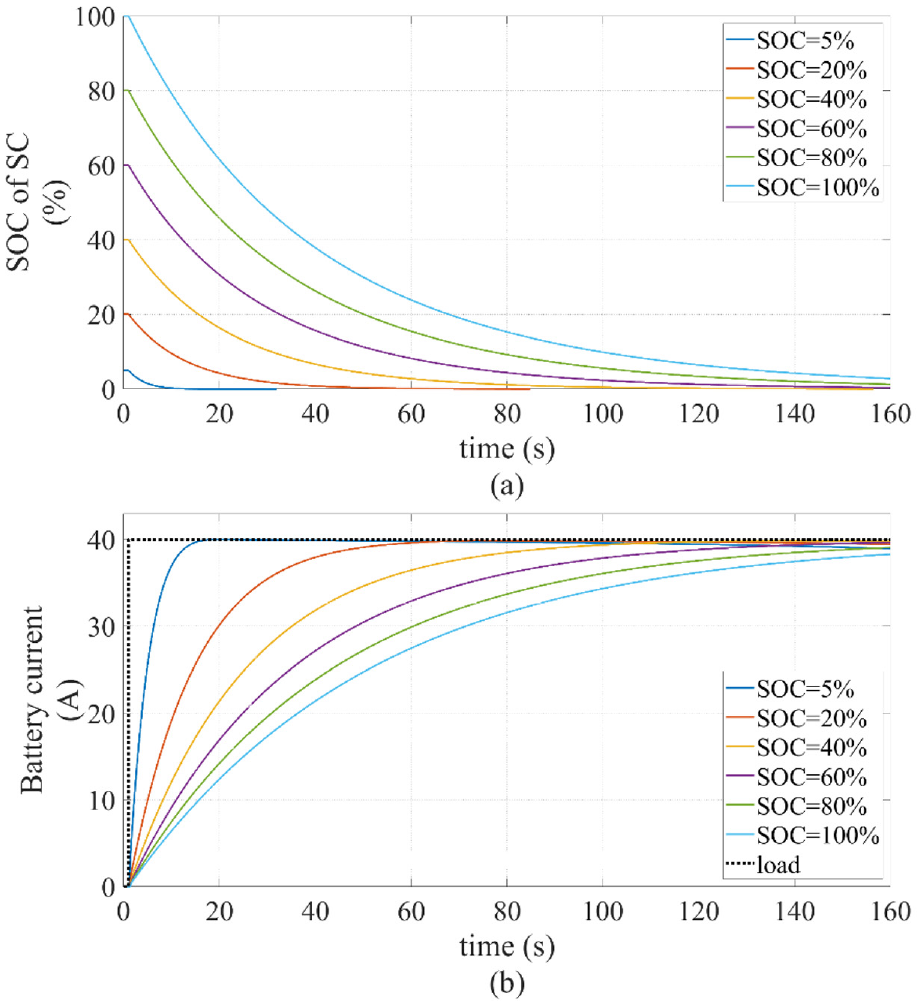
SC SOC and battery current under step load current: (a) SOC of SC, and (b) battery current.
In EV applications, the load of the ESS is related to the road conditions and the driver’s driving habits. Batteries and SCs in HESS systems typically have different current response under different loads. The next test aims to validate the effect of different cut-off frequencies on the change of battery power output under different loads of the system when the SOC of the SC is 50%. Figure 9(a) shows the effect of different fixed
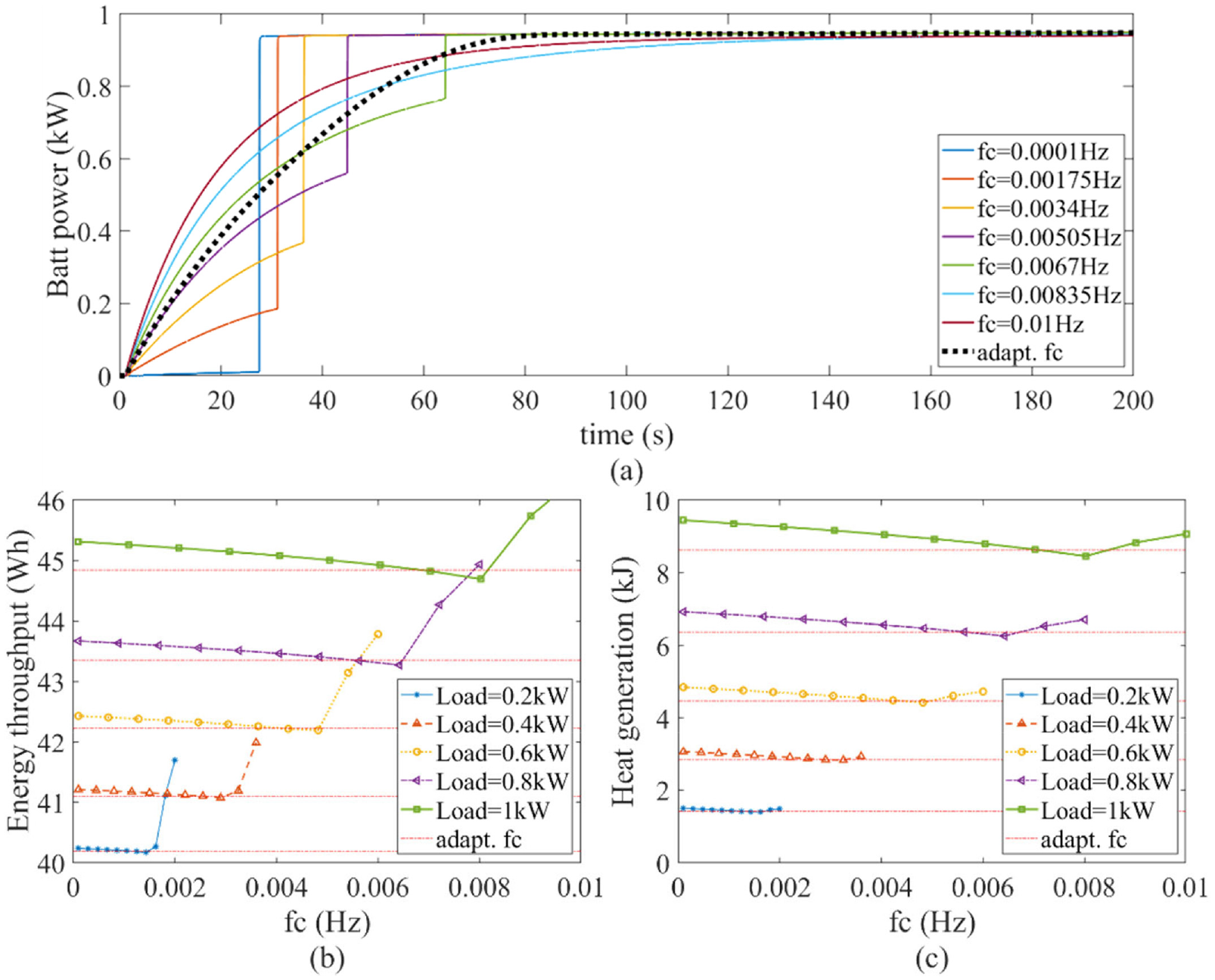
Comparison of optimal constant and adaptive cut-off frequency in battery output power, energy throughput and heat generation: (a) Output power of battery under different cut-off frequency, (b) energy throughput of battery under different load, and (c) heat generation of battery under different load.
To validate the usage of battery under the load, the energy throughput, which is calculated as the integration of absolute power output from the battery, is used as the index to show the consumption of battery life cycles. In addition to the energy throughput, the heat generation is also significant as it is proportional to the current square. Thus, even with the same energy throughput, the higher current will generate more heat inside the battery and finally cause higher temperature, which can lead challenges to the thermal management of the ESS. Figure 9(b) and (c) show the energy throughput and heat generation of the battery caused by different
The adaptive algorithm and control system are designed based on the simplified converter model without considering the real power loss. However, the power loss model of converter is used in the system plant model. The power loss model aims to simulate the real power loss conditions and tested whether the adaptive algorithm can still track the optimal point. Under this, the result shows that the adaptive control method reaches the energy throughput that is about 2% higher than the manually tuned optimal cut-off frequency. The difference is caused by the power loss of DC converter that has been neglected in the controller design. In future works, the power loss model will also be considered in the controller design to further improve its control performance.
Dynamic current loads
The previous case evaluated the effectiveness of adaptive cut-off frequency algorithm in step change with infinite time. In practical applications, the load current is not kept unchanged. The next case aims to test the adaptive algorithm with random step change load current. The result in Figure 10 compares the control performances of constant cut-off frequency and adaptive cut-off frequency algorithms. The constant cut-off frequency is set as the mean value of the load frequency, which is set to 0.01 Hz, to suit all load conditions, as shown in Figure 10(a). The load current is randomly changed, and the controller cannot predict the changing frequency of the load. The constant cut-off frequency-based LPF filtered out the changed load current into slow-varying current demand for the battery. The duty cycle of DC converter is shown in Figure 10(b) and the battery and SC current output are compared in Figure 10(c). From the result, the SC output covers the high transient and rapid change load currents, while the battery output covers the slow-varying and filtered current responses. In the adaptive LPF algorithm, the cut-off frequency is varying according to the SOC of SC and load current, as shown in Figure 10(d). From which it can be clearly seen that the SOC changing range of SC is wider than the traditional LPF. The adaptive LPF algorithm insured that the SC SOC will not exceed the limit and at the same time maximise the usage of SC to protect the battery. Due to this, the duty cycle of DC converter changes more frequently, as shown in Figure 10(e). As the result, the battery current output is not only based on the load but also considering the remaining energy of the SC, as shown in Figure 10(f).
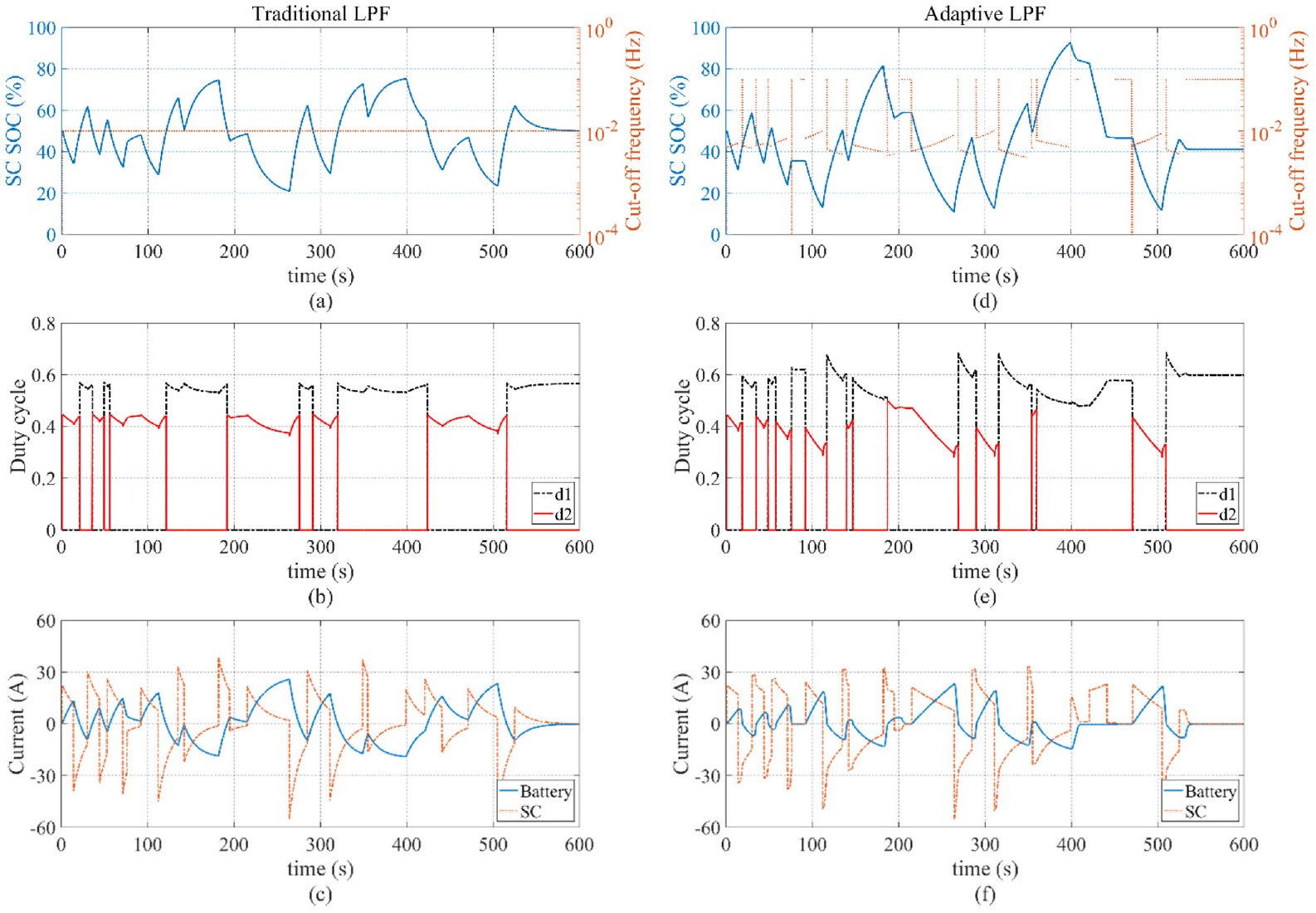
The control performance between constant and adaptive cut-off frequency under variable step changes: (a) SC SOC and corresponding cut-off frequency, (b) duty cycles and (c) battery and SC current of using traditional LPF, (d) SC SOC and corresponding cut-off frequency, (e) duty cycles, and (f) battery and SC current of using adaptive LPF.
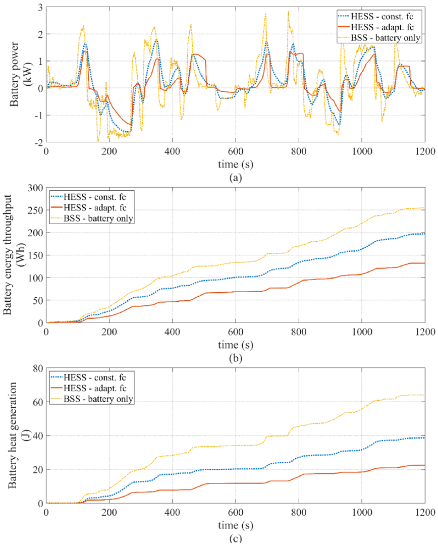
The comparison of battery output power among battery storage system (BSS), the HESS with constant cut-off frequency, and the HESS with proposed approach of adaptive cut-off frequency under the same load is shown in Figure 11(a). In the BSS, as the battery is the only power source, its battery output power is the same with the load power. From the comparison result, it can be found that the HESS with traditional LPF has slower change than the battery-only BSS. However, the HESS with adaptive LPF has even slower battery output power and faster response speed when the load direction has been changed. That means when the ESS changes from charge mode to discharge mode, or in the other way, the adaptive LPF can response faster than the traditional LPF to reduce the unnecessary power flow between the battery and SC.
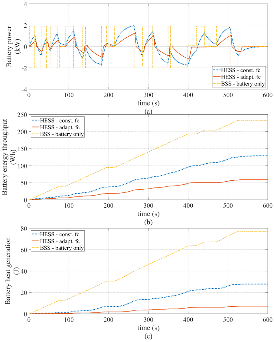
Comparison of battery output power, energy throughput, and heat generation among three approaches under variable step changes: (a) Battery output power, (b) battery energy throughput, and (c) battery heat generation.
Due to the frequent change between charge and discharge, the battery aims only support the long-term and low current power output. The charge and discharge cycles should be covered by SC as much as possible. Therefore, a better HESS control strategy will lead a lower battery energy throughput under the same load. To validate the effectiveness of reducing the usage of battery, the comparison of battery energy throughput is shown in Figure 11(b). The result shows that the HESS performs obviously better than the BSS due to the use of SC. Also, adaptive LPF-based HESS shows an even lower energy throughput than the traditional LPF-based HESS. The comparison of battery heat generation is shown in Figure 11(c).
To quantify the improvement of the proposed control approach, the maximum battery power output, final energy throughput, and heat generation in this case have been compared in the bar chart shown as Case 1 in Figure 14. From the result, it is found that the maximum battery power output of the proposed adaptive LPF-based HESS is nearly 35% less than that of the HESS with constant LPF and BSS. The HESS with adaptive LPF reduces 54% energy throughput and 75% heat generation compared with the HESS with traditional LPF and reduces 75% energy throughput and 91% heat generation if compared with BSS under the same load.
Real-world drive cycle power demand
Apart from the square-wave-shaped load, the next case tested the algorithm using real-world drive cycle power demand as load. Different with the random-changed step load, the real-world drive cycle is time-varying and continuous, and its derivative is continuous. The drive cycle of load data is recorded from a real vehicle. The result is shown in Figure 12.
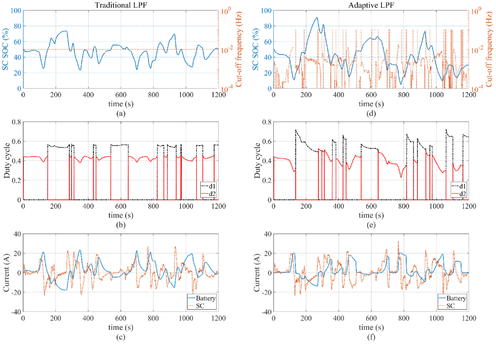
The control performance between constant and adaptive cut-off frequency under dynamic drive cycles: (a) SC SOC and corresponding cut-off frequency, (b) duty cycles and (c) battery and SC current of using traditional LPF, (d) SC SOC and corresponding cut-off frequency, (e) duty cycles, and (f) battery and SC current of using adaptive LPF.
Similar to the previous case, the SC in the HESS with adaptive LPF has wider range in operation than that in traditional LPF due to the adaptive cut-off frequency comparing between Figure 12(a) and (d). In the comparison of current, it clearly shows that the battery current in adaptive LPF is smoother and less fluctuation.
The comparison of battery power output among the three approaches have been given in Figure 13(a). The result shows that the HESS with adaptive LPF has obvious lower battery power output than the other two. The maximum battery power output of the adaptive LPF-based HESS is about 23% less than that of traditional LPF-based HESS and 51% less than that of BSS. Figure 13(b) and (c) compare the battery energy throughput and heat generation among these three approaches. The result shows that the adaptive LPF performs less energy throughput and heat generation on battery. To quantify the improvement, the HESS with adaptive LPF reduces the energy throughput by 33% and 48% compared with the other two approaches and reduces the heat generation by 42% and 65%, respectively, shown as Case 2 in Figure 14. This simulation result shows that the proposed adaptive algorithm can reduce the usage of battery and therefore extend the longevity of the whole HESS system and reduce its risk of battery thermal runaway due to heat generation.
Comparison of battery output power, energy throughput, and heat generation among three approaches under dynamic drive cycles: (a) Battery output power, (b) battery energy throughput, and (c) battery heat generation.
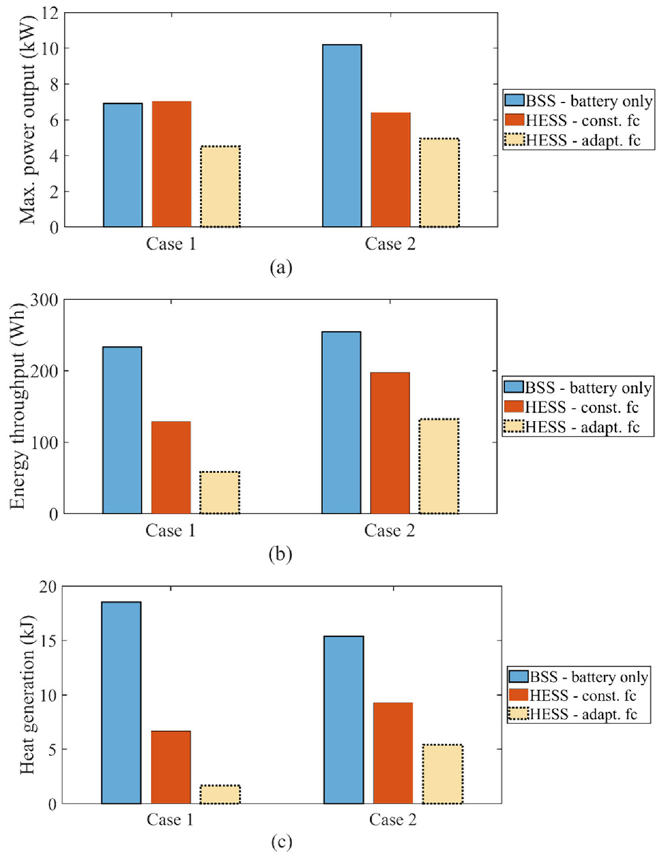
Bar chart comparison of final control performance among three approaches: (a) Maximum power output of battery, (b) battery energy throughput, and (c) battery heat generation.
With the adaptive algorithm, the usage of SC can be maximised whatever its size and capacity. This can be validated using the same real-world drive cycle under different size and capacity of SC in the HESS system. Figure 15 shows the performance of the proposed adaptive algorithm by comparing the final battery energy throughput at the end of the drive cycle and average system efficiency between fixed cut-off frequency and adaptive cut-off frequency. In this context, the system efficiency is defined as the ratio of load energy consumption to battery energy throughput.
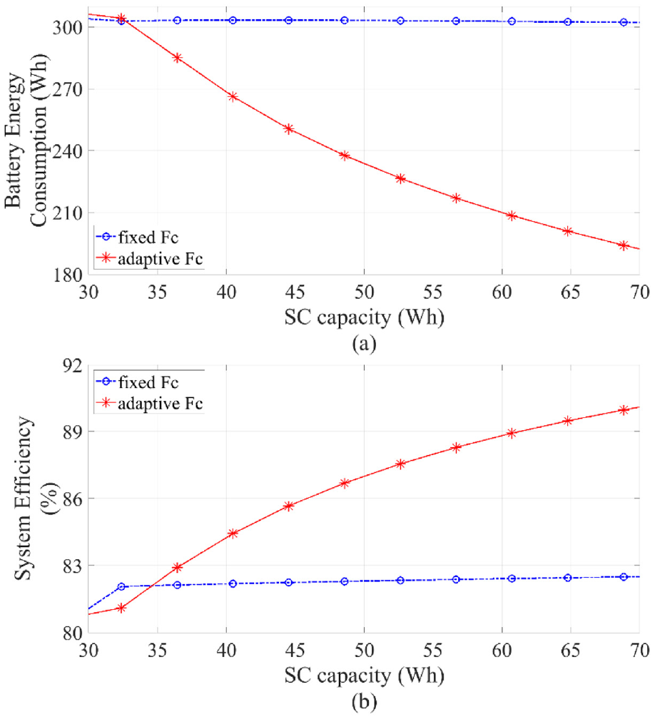
Battery energy throughput and system efficiency under different SC capacity: (a) Battery energy throughput, and (b) system efficiency.
The result indicates that the minimal SC energy capacity is around 33 Wh in this case study. When the SC capacity is below this value, the SC is too small to support enough energy capacity for transient power response to help improve the performance of the HESS. The battery is then used too much that can rapidly reduce its service life and the system efficiency. When the SC capacity is above this value, its energy capacity can support the transient power as designed. With using the fixed cut-off frequency-based power distribution scheme, both the battery energy throughput and the system efficiency are kept no change at their designed value by increasing the SC capacity. With using the adaptive algorithm, the battery energy throughput is reduced from 300 to 195Wh if there is an increase in the SC capacity from 33 to 69 Wh without any changes on the control parameter settings. The result validates that the algorithm can maximise the usage of SC according to its stored energy and load current and therefore reduce the unnecessary use of the battery. In addition, as the SC has smaller internal resistance than battery and the usage of DC converter can cause additional power loss, the algorithm reduced the usage of battery and DC converters and thus the system efficiency has been improved from 81% to 90% by doubling the SC capacity in the case study.
Discussion and future works
This paper focuses on the algorithm design of adaptive cut-off frequency. The structure of the power distribution scheme uses a popular and simple filter-based controller to split power by frequency and diverge high-frequency power to SC. The test in simulation verifies the performance of the proposed algorithm of adaptive cut-off frequency in two case studies of both the step-changed load and real-world drive cycle of EV. In both simulation studies, the results show that the adaptive cut-off frequency can increase the usage rate of SC and thus reduce the energy throughput of battery. As the cycle life of battery is the main service limits of the HESS, the reduction of battery energy throughput in normal operation can therefore increase the service life of the whole HESS system. In addition, the heat generation of the ESS is proportional to current square and the internal resistance of the battery is generally much larger than that of the SC. Therefore, when a high current flows through the battery, its heat generation will increase exponentially, which will make the battery under the risk of thermal runaway issue. The result verifies that the adaptive LPF designed in this paper can adaptively adjust the output power of the battery according to the load and the remaining energy of the SC, reduce the possibility of large current flowing through the battery, and finally reduce the heat generation of the battery. It can be concluded that the advantages of the adaptive LPF designed in this paper not only include the simple structure and low control complexity but also can adaptively adjust the battery output power under different loads to achieve the optimal performance of using SC. Therefore, the proposed approach can significantly reduce the energy throughput and heat generation of the battery without increasing its computational costs or changing the control structure, thereby prolonging the service life of the ESS and reducing the difficulty of thermal management with minimal modification.
Moreover, the effectiveness of the adaptive algorithm to reduce the battery energy throughput and increase the average system efficiency under different capacities of SC has been validated using the real-world drive cycle of load power. This verifies that when the capacity of SC exceeds its minimal sizing, the adaptive algorithm can adjust the cut-off frequency to maximise the usage of SC according to its stored energy and load current. However, the optimisation in sizing the SC and battery components is not considered in this paper.
The future work will be focusing on the following aspects.
The hardware implementation and experimental validation of the proposed algorithm;
Extending the algorithm to include the battery degradation and temperature impact on its internal resistance and capacity;
Transferring the technology to different topologies and architecture, including mixed battery systems of different age and chemistry;
Optimisation of the component sizing aspects of battery and SC in the HESS considering both the technical performance and costs;
In addition, a more detailed power electronics model of DC converter will be studied to consider both the conduction loss and the switching loss of power electronics under different switching frequencies.
Conclusion
This paper proposed an adaptive power distribution scheme for battery/SC HESS to improve the service life of battery. The approach uses an LPF with adjustable cut-off frequency, which is calculated according to the stored energy of SC and the real-time load power. The adaptive LPF is used to allocate the power generation/recovery of battery and SC and thus can maximise the usage of SC in either heavy load or light load. As the approach just changed the fixed cut-off frequency of traditional LPF with the adaptive algorithm, the whole structure of control system is not changed and thus its original property of simple and stable has not been affected. The simulation study verifies the effectiveness of the proposed adaptive power distribution scheme in battery/SC HESS and its stability is proved using Lyapunov method. The performance of the result shows that the adaptive power distribution scheme with adaptive cut-off frequency-based LPF reduced the usage of battery and therefore increased the service life of the whole HESS system. In addition, the adaptive approach can adjust the dynamic response of the HESS according to the capacity of SC and results in significantly reduced battery energy throughput and heat generation without changing its control structure. The proposed approach uses minimal modifications to maximise the usage of SC and thus will have potential to be widely applied in EVs and other applications.
Footnotes
Declaration of conflicting interests
The author(s) declared no potential conflicts of interest with respect to the research, authorship, and/or publication of this article.
Funding
The author(s) received no financial support for the research, authorship, and/or publication of this article.