
Abstract
To secure the data accuracy while reducing development cost of robot, in this article, we conducted fusion estimation of the information measured by strapdown inertial navigation system and the information solved by forward kinematics using extended Kalman filter and regarding the motion parameter error was proposed as state variable. On this basis, state equation and detecting equation can be established. In addition, this article made innovative attempt to compensate the optimal estimation of motion parameter error using feedback correction method, and finally obtained stable and accurate velocity estimation of robot. Being unrestricted by the number of robot’s leg, this method is suitable for both static gait and dynamic gait, and can overcome the impact from leg slipping. As for the verification of this method, in this article, a quadruped robot was employed for motion simulation and experimental verification, and results verified the correctness and feasibility of the proposed method.
Keywords
Introduction
Mobile manipulation is a widespread term used to refer to robotic systems consisting of one or two robot arms mounted on a mobile platform, which allows robot to perform tasks with locomotion and manipulation abilities. Starting from 1980s, the development of mobile manipulator has been experiencing several focusing on different key components in both hardware and software.1–4 In most conventional teleoperation systems, the environmental information is supposed to be feedback to the operators directly, and they thus have to take care of every single interaction with the environment around the manipulator. The operator could manipulate a telerobot in this manner easily when the environment is simple, but in a dynamic and uncertain environment, this approach could result in extreme huge burden to the operator. 5 As a major component sector of robot, the legged robot is one of the most versatile design strategies for robot locomotion. 6 The legged robot can be usually categorized into biped robot, quadruped robot, and hexapod robot. With only a group of point contact and a proper site as landing point, the legged robot can smoothly and effectively cross road obstacles. Therefore, the legged robot is more suitable for working in highly complex real world. 7 The legged robot has become the focus in bio-robot research. Presently, the walking of excellent multi-legged robots mainly depends on the sensing system, control strategy, initial gait planning, and so on. 8 To realize the motion control of legged robot, it is needed to acquire accurate real-time motion parameters for their position control, especially when a robot has to choose its foothold while it is running at a demanding speed. 9 Recent technology advances allow to create robots equipped with several kinds of sensors. 10 The information from the legged robot and environment can be obtained by the sensing system. 8 In state estimation of mobile robot, normally Global Positioning System (GPS), 11 inertial navigation system (INS), 12 Visual Odometer, 13 and ultrasonic distance measurement 14 are selected as reference information. Since legged robot is an independent automatic system, it can perform the whole movement according to surround environment. GPS can provide the absolute location of robot; however, GPS receiver is required to read data transmitted from four satellite simultaneously, which is a huge limitation, because in limited space such as downtown with high-rise buildings and dense forest, it is hardly possible to reliably receive four satellite data, of course, most deep indoor space cannot provide enough visibility of sky for the operation of GPS receiver. 15 Second, since the specific orbital paths of GPS satellite are along different regions of the earth, the resolution will be different. In addition, as transmitting through atmosphere, the accuracy will not be high enough; in this case, the application of high-precision Differential Global Positioning System (DGPS) will greatly increase cost. However, visual odometer makes extremely high demand on computer hardware. Processing velocity is normally the biggest reason that limits the application of visual odometer. Moreover, visual odometer is very sensitive to light condition, for example, in complex environment such as nighttime condition, fog day, dense rainforest, and dark indoor space, visual odometer can hardly achieve sound effect. In addition, ultrasonic distance measurement method is also easily to be affected by surrounding environment, thus the measurement accuracy is hard to be guaranteed. 16 The biggest problem is that the flight phase will appear when legged robot switches on dynamic gait operation, and relative slipping will be generated between robot foot and ground when operating on rough road, 17 making it impossible to directly measure the condition of a mobile robot, or conveniently calculate the motion parameters according to the wheel rotation as on wheeled robot or tracked robot. Therefore, it is difficult to obtain accurate motion state information of a legged robot.
For a long time, in order to guarantee high accuracy of motion parameters, people have to choose high-accuracy, strategic-level inertial navigation which is very expensive. Therefore, it is not the best solution even though the accuracy of instantaneous acceleration of each inertial navigation sample is satisfactory. The integral operation will make velocity error increase linearly with time, and make displacement error proportional to time squared. Long-term continuous use of inertial navigation will lead to dispersion of velocity and location information, which is a defect in the design theory of inertial navigation. 18 Therefore, inertial navigation can hardly meet the requirement when used alone. 15
Pei Chunlin et al. from the University of Pennsylvania have earlier estimated the motion state of legged robot based on leg kinematics. They conducted related researches using hexapod robot RHex. Suppose under the condition that the hexapod robot is completely on tripod gait (i.e. in each gait cycle, nonadjacent three legs touch the ground) and the ground is completely flat, this research team designed a set of legged odometer. Using the structural characteristics of hexapod robot, they calculated and obtained the transformation matrix of robot body in world coordinate system, and thus obtained the location of center of mass in world coordinate system. 19 Due to the accumulation of computing error, this legged odometer still suffers drift. In the later work, this research team fused the location information measured by kinematics with inertial measurement unit (IMU) information, so as to better estimate the real-time motion state. 20 However, this method is only suitable for robot on tripod gait, which does not consider its application on dynamic gait or the impact brought by foot slipping. Researches on mammal and arthropod have indicated that the motion location information of animal itself can be effectively estimated by only inertial information and joint information. 16 Inspired by this, M Reinstein from the Czech Technical University and M Hoffman from the University of Zurich, based on data-driven principle and by conducting large amounts of experiments, successfully found approximation relation among robot step-length, angular transducer of hip and knee joint, and foot-end contact forces, and then multiplied with step frequency to obtain the approximate real-time velocity of robot. Through fusing the approximate real-time velocity with data measured by onboard inertial navigation, the location and velocity of robot can be obtained. This method is suitable for condition with a certain velocity range of 0.08–0.21 m/s and multi-type grounds, and can even overcome the impact caused by foot slipping. The limitation of this method is that velocity training cannot be completed without conducting large amounts of experiments, and state estimation method is of poor adaptability for different types of robots and different gaits.
As previously mentioned, there are different characteristics between using external reference information and using robot body sensor information. Therefore, some researchers have integrated IMU, 21 external reference, 18 and robot body sensor, 22 making it possible to select the optimal reference information according to different working situation.
It seems that the problems mentioned before have been solved; however, in actual practice, external environment is complex, changeable, and of low reliability, and moreover, the sensor used for collecting external information is normally very expensive, therefore, measures should be considered in the aspect of expansion of robot production scale and robot use range, simplification of hardware processing technology, and assure the maximum economical effectiveness before making robot enter human daily life. 23
This article adopts the existing low-cost civilian inertial navigation Crossbow NAV440 in laboratory which costs less than US$10,000. Both of its forward velocity error and side velocity error are 0.4 m/s. The civilian inertial navigation, of which the accuracy is although far lower than that of strategic-level one due to its inferior processing technology, has been widely employed for its lower cost. In order to overcome the interferences to civilian inertial navigation due to manufacturing error, installation error, and external factors such as slipping, it should obtain the location and attitude information of a legged robot. In this article, information collected by robot body sensor was fully utilized to provide basis for state estimation. Through the information returned by three-dimensional (3D) force sensor on foot end, it can determine the touchdown foot. After that, forward kinematics calculation was performed according to the attitude angle information and filter processed information returned by linear displacement sensor on joints of touchdown foot. Perform the integral operation of acceleration information measured by inertial navigation, so as to obtain the measure value of location and velocity. Subsequently, the obtained results together with forward kinematics calculation results were put into the improved extended Kalman filter (EKF) framework for estimation and correction, thus obtaining the optimal motion state information of the robot.
Forward kinematics of quadruped robot
The 3D model of the quadruped robot is shown in Figure 1. Each leg has side-sway hip joint, front hip joint, knee joint, ankle joint, and passive line elastic component. Each joint is driven by hydraulic cylinder and equipped with displacement sensor. In this article, linear displacement sensors were installed on the joint areas of the quadruped robot.

3D model of the quadruped robot.
This article adopts the existing low-cost civilian inertial navigation Crossbow NAV440 in laboratory. Figure 2 shows the definition of the navigation coordinate system N and the body coordinate system B.

Navigation coordinate system N and the body coordinate system B.
The direction cosine matrix
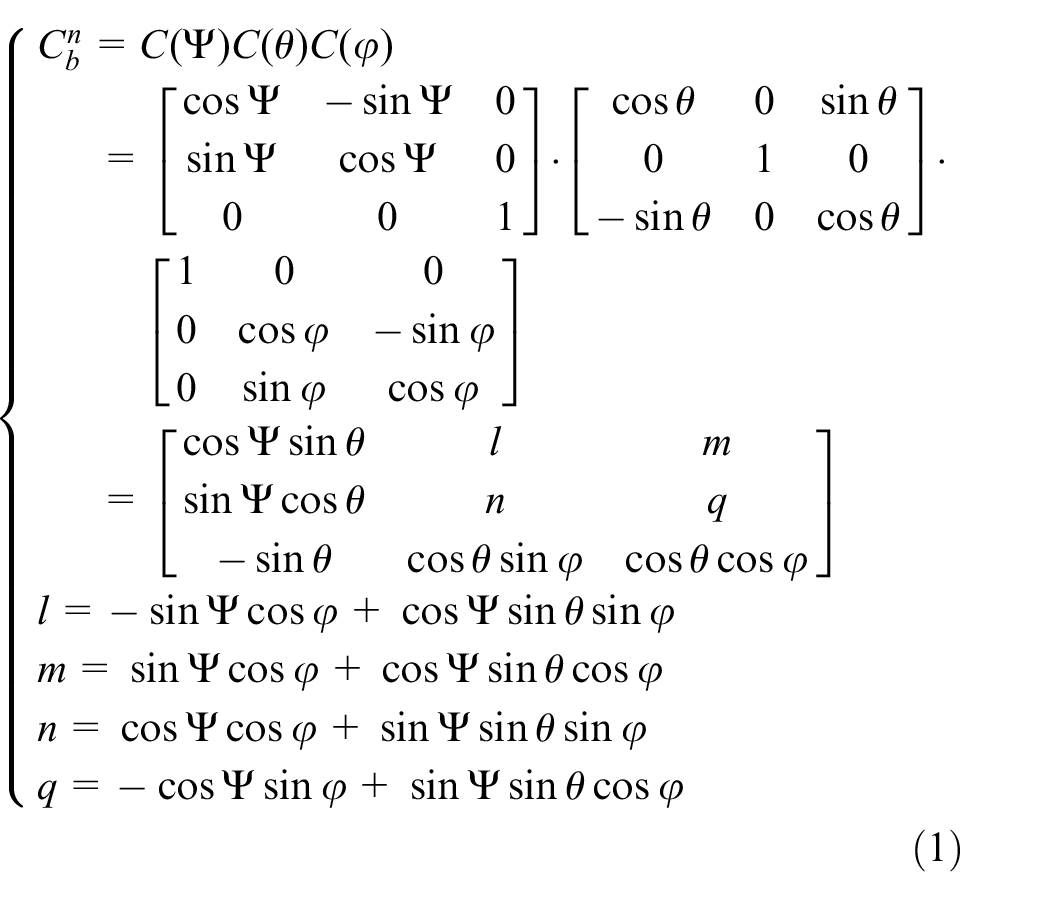
The ankles are in opposite vertex design, and four legs are in symmetrical arrangement. Therefore, forward kinematics analysis is performed by taking the “right-front leg supporting the ground” posture as the example. Since the displacement of passive line elastic component is small, inconvenient to be measured, and exerts less impact on kinematics calculation, it can be ignored when establishing the coordinate system of robot leg connecting rod. According to the principle of establishing coordinate system of DH joint, it can be seen that the coordinate system of link rod from center of mass to foot end is shown in Figure 3, based on which the D-H parameter table from side-sway hip joint to foot end is established and shown in Table 1.

Connecting rod coordinate system of right front leg of quadruped robot.
D-H parameter table of right front leg of the quadruped robot.

Here, the connecting rod angles are transverse joint angle
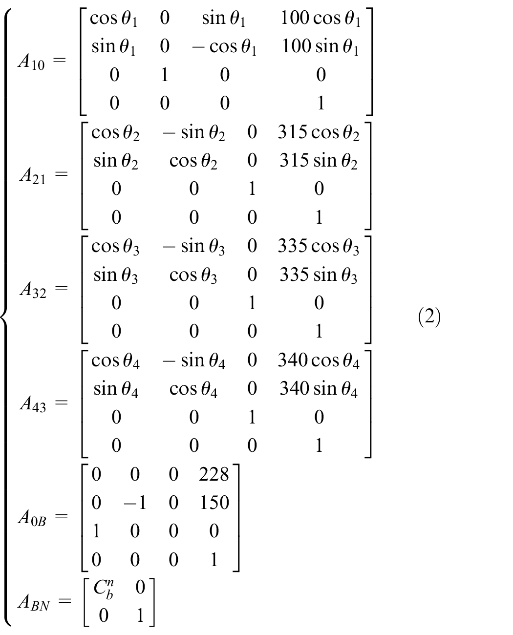
The homogeneous transform matrix

In calculation of movement velocity of mass center, the arithmetic product of Jacobian matrix and joint angular velocity was avoided. Because in the moving process of a legged robot, there are serious shocks emerging, and spaces existing in leg joints, leading to errors of displacement sensor data. Therefore, directly using differentiation to calculate angular velocity will enlarge calculation errors.
Specific calculation method is as follows: calculate robot body displacement distance for every 10 sampling periods (sampling frequency is over 200 Hz). The average velocity shown in equation (4) can be obtained. This method can remove the impact of shocking vibration, and effectively improve the calculation accuracy. Considering the real-time performance, 0.05 s of lag is within the permissible range

where
EKF of quadruped robot
EKF
INS is a typical nonlinear system, so EKF is adopted as the data fusion algorithm. The EKF algorithm is restricted to modeling every variable as a Gaussian random variable. 24 According to the working mechanism of strapdown inertial navigation system (SINS), state equation will be established, and forward kinematics calculation is regarded as measured value to improve the EKF algorithm and perform motion state estimation. Finally, the velocity estimation algorithm is verified by virtual prototype simulation of quadruped robot.
Proposed by RE Kalman at 1960 for the first time, Kalman filter has been widely used in present various fields, especially auto-navigation, for its advantages of digital filtering. 25 Normally, Kalman filter is used to solve the estimation problem of a group of state variables x in linear system. While regarding the nonlinear system, state variable and measurement variable normally meet certain nonlinear functions such as equation (5)

where
In this case, Kalman filter is not applicable any more, and instead, the EKF is the widely used one. The specific method is to conduct linearity of

Thus, the optimal estimation of state variable is calculated according to the recurrent process of Kalman filter.
Prediction model of EKF for quadruped robot
In the state estimation of INS, normally carrier’s location and velocity are regarded as state variables. However, since the values of these parameters vary a lot between each other, directly selecting them as state variables or measure variables will probably lead to ill-conditioned equation, and thus causing result error in the end. Therefore, in robot navigation system, errors of displacement and velocity are usually selected as state variables or measure variables.
To realize dynamic bias compensation, in this article, SINS bias, as state variable, was introduced into the state equation. The outputs of accelerator and gyroscope include bias and noise. See equation (7), where the derivative of bias and random error is regarded as the Gaussian noise
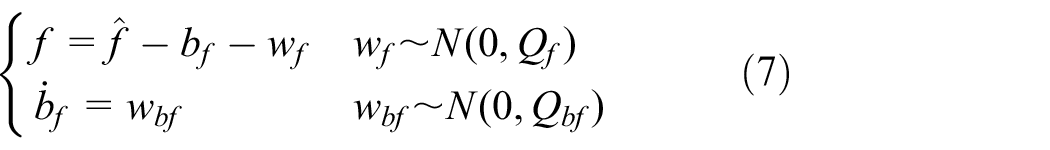
where
The differential equation of state variable should be first established before deriving the state equation. The velocity updating differential equation of SINS is expressed as equation (8)

where
In equation (8),

According to equations (7) and (9), the differential equations of displacement, velocity, and acceleration bias can be obtained, which are expressed in equation (10)

Because the differences among the magnitudes of these parameters (

where
To calculate the differential equation of state variable

Equations (11) and (12) are arranged into matrix forms, which are expressed in equation (13)

Equation (13) can be simply denoted as equation (14)

where

To facilitate computer programming processing, differential models of above errors should be discretized, so as to obtain the discrete state equation shown in equation (15)

where

To simplify the equation, we use the random noise

Measurement model of EKF for quadruped robot
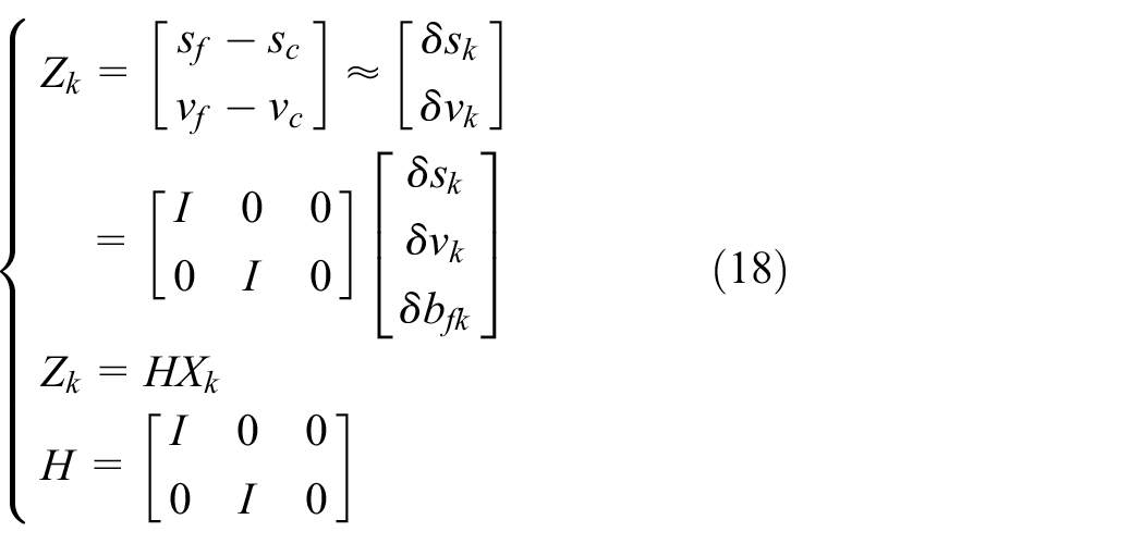
Previously, the displacement
Estimation of EKF for quadruped robot
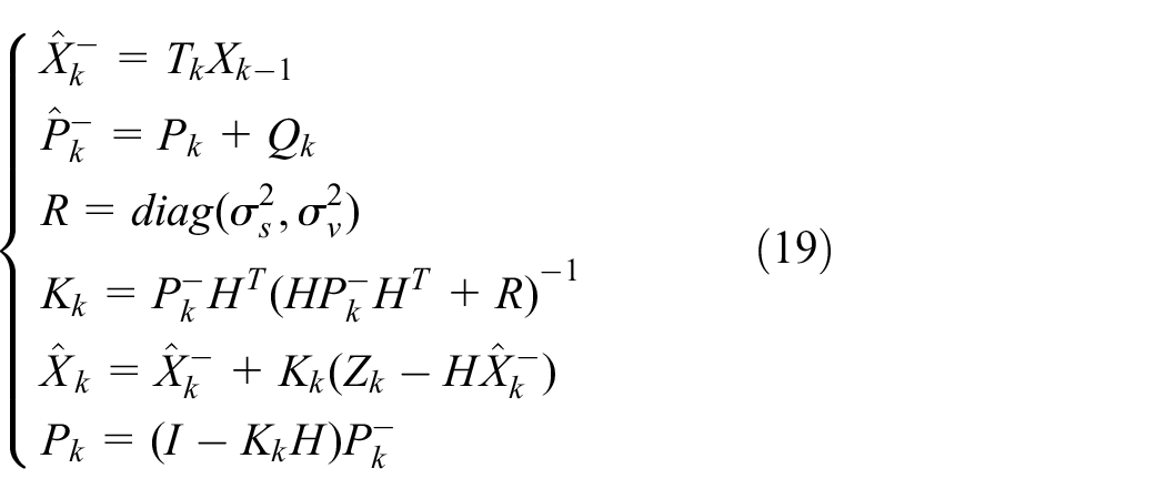
As state equation and measurement equation have been respectively established, according to the recurrent processes of equation (19), the estimation values of above state variables can be calculated by adjusting covariance parameters
After obtaining the estimation of displacement and velocity errors, the feedback compensation is performed for navigation system. The theory of feedback compensation is to compensate the displacement and velocity by feeding the error estimations which have been obtained by EKF back into navigation calculating process before conducting navigation calculation and obtaining relatively accurate motion parameters. Equation (20) corrects the navigation calculation results
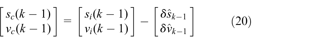
where
Equation (21) upgrades the navigation calculation results on the basis of corrected results in equation (20) as the required motion parameters. This correction method inhibits the drift of navigation calculation results, so as to guarantee the small magnitude of EKF module input and avoid EKF divergence
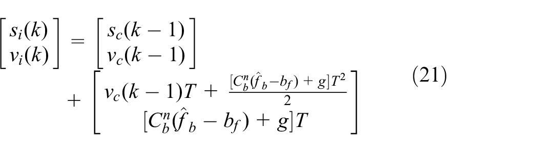
where
Numerical experiments
To preliminarily verify the effectiveness of above estimation algorithms, the velocity estimation simulation experiment is conducted by taking the quadruped robot as example. In the experiment, the Trot motion of quadruped robot is simulated using motion simulation.
In post-processing of simulation results, the acceleration of carrier’s mass center is extricated, and then the SINS can be simulated by manually adding Gaussian noise and constant bias. Extricate hydraulic cylinder displacement of each joint and foot applied force, and add Gaussian noise to approximately simulate the robot body sensor. The recorded velocity of carrier’s mass center is selected as the reference value for velocity estimation.
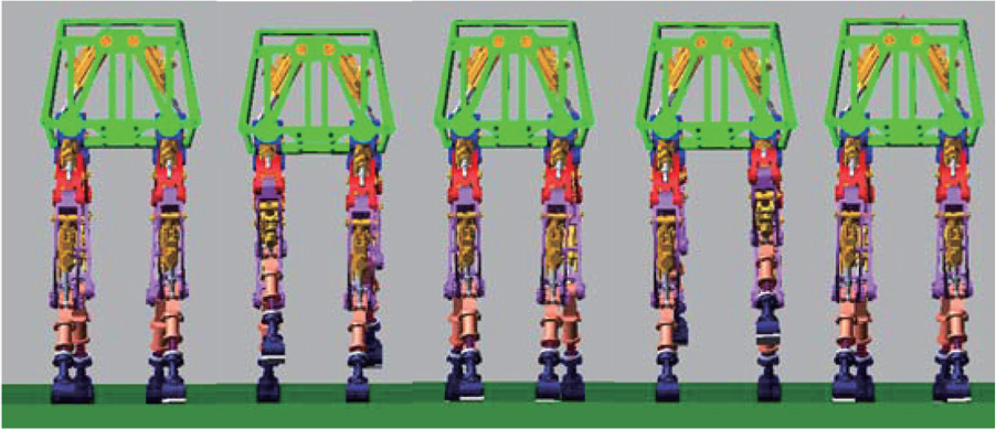
Through building the control system, the joint simulation of quadruped robot under Trot gait can be realized. The forward velocity of robot is maintained around 0.8 m/s; simulation time is set as 12 s. The motion process is shown in Figure 4.

Forward motion process of quadruped robot on flat ground.
In post-processing, the data which are necessary for data fusion should be extricated as virtual sensor data. To better compare with real situations, it is suggested to add Gaussian white noise and constant bias into virtual sensor. Navigation solution can be obtained according to equation (11), and displacement and velocity can be obtained according to equations (2)–(4). Through EKF data fusion by equations (26)–(31) and equations (32)–(33), displacement and velocity estimation results can be obtained, as shown in Figure 5. In this figure, the red full line represents the velocity estimation, short blue dash line represents the forward kinematics calculation value, black dot dash line represents the results of navigation velocity calculation, and long green dash line represents the real motion parameter. In addition, it can be seen from the figure that due to the existence of deviation, velocity calculation is subjected to fast drift. Impacted by linear displacement sensor noise, the error of forward kinematics calculation is relatively large. However, after data fusion, the velocity estimation is very close to its real value. Analytic calculation of error between velocity estimation and velocity real value is as follows: root mean square (RMS) error of forward velocity is 0.0383 m/s with the largest error less than 0.09 m/s; RMS error of side velocity is 0.0183 m/s with the largest error less than 0.09 m/s.
Velocity estimation result of forward motion simulation of quadruped robot.
In actual situation, the side motion of robot should normally be controlled; therefore, there is also a high level of requirement on the estimation accuracy of side velocity. To verify the estimation effect of side velocity, side step simulation experiment is conducted, wherein the simulation is 12 s and the step velocity is about 0.2 m/s. The side step motion is shown in Figure 6.
Side step motion simulation of quadruped robot on flat ground.
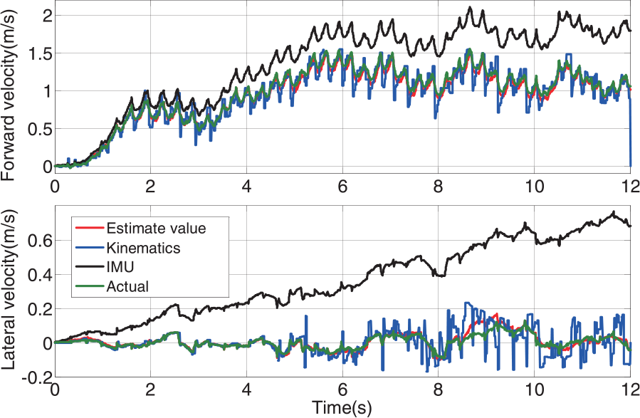
The velocity estimation is shown in Figure 7. In the figure, the red full line represents the velocity estimation, short blue dash line represents the forward kinematics calculation value, black dot dash line represents the velocity calculation result of inertial navigation, and long green dash line represents the real value of motion velocity. In addition, it can be found that velocity calculation is subjected to significant drift, and forward kinematics calculation suffers errors; however, after data fusion, the estimated velocity is very close to real velocity. The analytic calculation of error between velocity estimation and real velocity value is as follows: the RMS error of forward velocity is 0.0116 m/s with the largest error less than 0.05 m/s, while the RMS error of site velocity is 0.0148 m/s with the largest error less than 0.05 m/s.

Estimation result of side step velocity of quadruped robot.
Different from walking on flat ground, robot walking on rough ground may easily encounter following problems: (1) due to the ground undulations, a pair of diagonal feet may touch the ground non-simultaneously; (2) emergence of hang phase, and shorten ground-touching period; and (3) large shock from ground, serious body vibration, and more drastic changes in joint angle, attitude, and acceleration. All the above factors will lead to severe decrease in accuracy of forward kinematics calculation (i.e. the credibility decrease in calculation results), thus impacting the estimation effect of velocity.
To verify whether the velocity estimation is effective when robot is working on rough ground, in this article, we built a rough road with maximum drop of 5 cm, and then we conducted simulation of the rough ground with simulation time of 12 s and walking velocity of about 1 m/s. The simulated motion process is shown in Figure 8.

Walking simulation of quadruped robot on rough ground.
In Figure 9, the red full line represents the velocity estimation, short blue dash line represents the forward kinematics calculation result, black dot dash line represents the velocity calculation result of inertial navigation, and long green dash line represents the real motion parameter. In addition, it can be seen from Figure 9 that due to the problems that are encountered by robot waling on rough ground, the error of forward kinematics calculation, especially the error of side velocity, decreases significantly; however, it can generally track the velocity variation trend of carrier. Through analysis of experiment data, after data fusion, the velocity estimation is close to the real velocity value. The analytic calculation of error between velocity estimation and real velocity value is as below: the RMS error of forward velocity is 0.0196 m/s with the largest error less than 0.07 m/s; The RMS error of site velocity is 0.0129 m/s with the largest error less than 0.05 m/s. Therefore, such velocity estimation algorithm can overcome the impact of shock and vibration, and can estimate the accurate velocity variation in different ground surface environments.

Estimation result of walking velocity of quadruped robot on rough ground.
Velocity estimation experiment of quadruped robot
The experimental prototype of the quadruped robot employed is shown in Figure 10. Robot body is equipped with power system which consists of engine, variable pump, and hydraulic accessories, providing power for the hydraulic cylinder of each joint. By the means of wireless transmission, the operator send instructions to on-board controller through control box, so as to control the walking gait, forward direction, and forward velocity.

Platform of quadruped robot.
Based on experimental prototype on flat ground, the robot is set on Trot gait, walking for 5 min at roughly 0.45 m/s; the robot motion process is shown in Figure 11.

Screenshot of walking experiment of quadruped robot prototype.
Based on the data of the SINS, the joint displacement sensor, and the 3D force sensor, navigation solution can be obtained according to equation (11), and displacement and velocity can be obtained according to equations (2)–(4). Through EKF data fusion by equations (26)–(31) and equations (32)–(33), displacement and velocity estimation results can be obtained. Quadruped robot and its accessory equipment as a whole are oversized, and its motion range has been far beyond the valid range (normally
In Figure 12, the red full line represents the velocity estimation, while black dash line represents the navigation calculation value. Due to the deviation of inertial navigation, conducting navigation calculation using inertial navigation data only will cause severe drift; however, within each short period, it can still accurately reflect the motion velocity variation of the robot body. As can be seen from the figure, the velocity estimation result can fully track the motion trend of SINS, indicating that velocity estimation indeed maintains the feature of short-time accuracy of inertial navigation, and no drift occurs within, which basically verifies the effectiveness of such data fusion method for real-time motion state estimation of the robot.

Comparison between velocity estimation and navigation calculation result.
Conclusion
Motion state estimation is the key technology to improve the motion control ability of mobile robot, and also a key research direction of robot navigation technology. A legged robot is subjected to non-continuous supporting, multiple shock vibration, and inertial navigation drift, all of which increase the difficulty in its motion state estimation. In this article, we used relative low-price civilian inertial navigation Crossbow NAV440, and properly improved EKF according to the structural features of legged robot. To secure the small magnitude of EKF input, the error values of motion parameters were selected as state variables, and established state equation and measurement equation according to the working mechanism of SINS and forward kinematics information. Through selecting feedback compensation method, the error estimations were compensated. Such algorithm, by integrating the short-time accuracy of inertial navigation and the advantage of no drift occurs of navigation calculation, can improve the accuracy and robustness of the obtained motion information. Finally, we verified the correctness and feasibility of this algorithm through simulation and experiment. The divergence of navigation calculation was inhibited, and the real-time velocity estimation of the carrier can be obtained. Compared to the independent use of Crossbow NAV440, the method proposed in this article greatly improved the measurement accuracy of the forward velocity and the lateral velocity of the quadruped robot.
Footnotes
Handling Editor: Chenguang Yang
Declaration of conflicting interests
The author(s) declared no potential conflicts of interest with respect to the research, authorship, and/or publication of this article.
Funding
The author(s) disclosed receipt of the following financial support for the research, authorship, and/or publication of this article: This work was supported in part by the National Natural Science Foundation of China (grant nos 61375097 and 61473105), the Natural Science Foundation of Heilongjiang Province, China (grant no. F2015008), and the State Key Laboratory of Robotics and System (HIT; nos SKLRS201502C and SKLRS201603C).