
Abstract
In this article, a method was proposed for strapdown inertial navigation systems initial alignment by drawing on the conventional alignment method for stable platform navigation systems. When a vessel is moored, the strapdown inertial navigation system contributes to the disturbing motion. Moreover, the conventional methods of accurate alignment fail to succeed within an acceptable period of time due to the slow convergence of the heading channel in the mooring conditions. In this work, the heading was adjusted using the velocity bias resulting from the component of the angular velocity of the Earth on the east channel on the strapdown inertial navigation systems analytic platform plane to accelerate convergence in the initial alignment of navigation system. To this end, an extended Kalman filter with control signal feedback was used. The heading error was calculated using the north channel residual velocity of the strapdown inertial navigation systems analytic platform plane and was entered into an extended Kalman filter. Simulation and turntable experimental tests were indicative of the ability of the proposed alignment method to increase heading converge speed in mooring conditions.
Introduction
Initial alignment is the first work and crucial phase stage in strapdown inertial navigation systems (SINS). The objective of alignment is to provide a highly accurate initial attitude matrix between the navigation frame and body frame. 1 –3 In other words, the SINS needs to accomplish alignment before it starts the navigation phase. 4 Convergence speed and accuracy associated with initial alignment are two important criteria for INSs, so in many applications we need to do the initial alignment with precise accuracy and rapid speed. 5 Also, under mooring conditions, the SINS used in a ship suffers from the external disturbance components caused by the motions of the sea waves and wind waves, therefore a rapid and accurate alignment of a ship’s SINS is hard to achieve. Therefore, this problem has attracted the attention of many researchers recently. 6 –11 The gyrocompass and integrated alignment methods are conventional alignment methods which have been reviewed in the literature.
Gyrocompass alignment is built on the basis of classical control theory and the gyrocompass effect and applied in the platform INS, thus there is no need to establish an accurate mathematical model. 12 Also, gyrocompass alignment is a self-alignment method and does not require the covariance of a system and measurement noises. The general idea of this method is to use three control loops to adjust the roll, pitch, and heading initial angles. In the first step of gyrocompass alignment, horizontal leveling adjust of the platform accomplished by control law feedback from east and north velocity errors which gets through the integration of the east and north accelerometers. Also, the horizontal error angle is influenced additionally by the effect of azimuth error angle, and the projection value of gravity acceleration along northern axis in platform coordinate system will change. Therefore, azimuth error angle leads to the change of velocity error in the north. With using the north velocity error feedback for azimuth angle correction, the error diminishes over time and the platform coordinate match the navigation coordinate. 12 –14 This approach has been used in SINS for alignment with changes in its structure. 12 However, the basic of this method relies on static conditions and in the case of external acceleration caused by the sea waves will be inaccurate. 13
The other method is integrated alignment, which estimates misalignment angles based on the modern control theory. For the case of static conditions, this approach can accomplish alignment rapidly and precisely by using modern filtering methods. 14 –18 However, the estimation time is affected and increased by the distribution. Under the mooring conditions, the alignment process undergoes extra disturbed accelerations and angular velocities. 19 –22 Therefore, the vehicle had to wait for the fulfillment for a long alignment time and the alignment duration will be beyond 20 min. 23 To overcome this challenge, studies on alignment of SINS under mooring conditions have utilized different approaches.
In some research studies, the prefilters are used to attenuate the effect of external disturbed movements and sensor noise. In the studies by El-Sheimy et al. 24 and Nassar and El-Sheimy, 25 wavelet de-noising technique is used to cancel the high-frequency sensors noise effects. Li et al. 22 employed the cascaded finite impulse response (FIR) digital filters to attenuate disturbing accelerations, but these FIR filters are designed with very large orders to meet the de-nosing requirement and lead to the increasing of the computation burden. In the study by Sun and Sun, 26 the infinite impulse response (IIR) digital low-pass filter was used to reduce the influence caused by the disturbed movements on the gyroscope and accelerometer outputs with small filter orders. Nevertheless, all these digital filters lead to time-delay problems which are not suitable for real-time implementations. Combination of a Kalman filter and a IIR digital filter to filter the outer disturbances in a real-time way was proposed by Lü et al., 27,28 in which the computation time is much shorter than the wavelet methodology. Using of inertial frame-based alignment and the projection of gravity in the inertial frame, a new approach was proposed by Sun et al. 29 to calculate the attitude matrix between inertial frame and body frame. In this way, the disturbed movements can attenuate and quickly obtain the initial attitude matrix. However, the relatively high-frequency and non-periodical components of the disturbances would affect the alignment process accuracy in this method.
Recently, a method called forward and backward processes serving INS alignment has been proposed to solve the convergence speed problem. 5,30 –33 Modern computers can store numerous sensor data items, and the data could be processed repeatedly in both forward and backward sequences. A combination of the aforesaid method and Kalman filter has been used for alignment purposes, while the contradiction problem can be resolved through the forward and backward filter processes to process the saved inertial sensor data back and forth. Utilizing saved inertial measurement unit (IMU) data sufficiently may decrease the required implementation data length. Hence, the alignment duration can be reduced and a rapid fine alignment method can be obtained. The forward and backward compass processes can shorten alignment duration in the case of small sensor errors by adopting the scheme of the parameter settings, which is the main drawback of this method.
Inspired by the gyrocompass method and Kalman filter, we proposed a rapid SINS alignment algorithm in this article by employing the control signal feedback from the north velocity error. It is supposed that integrating attitude and velocity equations is done by the computer of the SINS. The proposed algorithm will attempt to estimate and correct SINS attitude errors. Using the linearized model of the SINS error and utilizing the zero average speed of the ships as measurement signal, the designed Kalman filter will estimate the attitude error. So, it is possible to correct heading and tilts errors by estimated errors. In the SINS error model, the heading angle convergence is very slow. The reason is that the Earth angular rate is too slow and the sensor noise is too large. Increasing the heading convergence speed is the main advantage of the proposed feedback from the north velocity error in comparison with existing methods. Therefore, the ship alignment time reduces without time-delay problems in the presence of the oscillation motion caused by the sea and wind waves.
The rest of this article is organized as follows. The coordinate frames used in this article are defined in the second section. In the third section, the conventional platform alignment method is presented. The SINS proposed structure is described in the fourth section. The results from both simulation tests are illustrated in the fifth section. Finally, the conclusion is presented in the sixth section.
Coordinate frame definitions
The coordinate frames used in this article are defined as follows: The n frame is the navigation frame with its origin at center of marine vehicles’ mass, the xn
axis points to the north, the yn
axis points to the east, and the zn
axis points to the downward. The b frame is the body frame with its origin at center of marine vehicles’ mass, the xb
axis points to the forward, the yb
axis points to the right of the vehicle, and the zb
axis points to the downward of the vehicle.
Conventional platform alignment method
The velocity error feedback method is used for initial alignment of platform INS. The general idea of this method is to use three control loops to adjust the roll, pitch, and heading initial angles. The pitch and roll control loops, based on the accelerometer output, create commands for stable platform motors to horizontally align the plane. In the closed loop, the output of two horizontal accelerometer channels at the first stage is aligned with the plane. In addition, the commutation is sent to the vertical channel motor through the integration of the north accelerometer based on the image of the Earth’s angular velocity on the eastern channel gyroscope (due to deviation from the east). In principle, this angular velocity of the east channel gyroscope accounts for the tilt in the stable plane. This tilt causes an image of the gravity acceleration on the north accelerometer. Integration of this acceleration is used to correct the heading channel. This rotation of the heading of the plane continues to a point where no further increase on the accelerometer of the northern channel is created. It means that the east gyroscope is located in the east and no longer has any image of the Earth’s angular velocity. Of course, the overall structure of the stable platform has complexities, and here the generalities of performance are expressed. This process can be used in a strapdown structure with a slight change in its functionality. The full description of the platform is provided in the studies of Ben 12 and Kouba, 34 while Li et al. 35 illustrate it in more details. These references are based on classical control.
SINS alignment structure
Conventional SINS alignment algorithms have used error model to estimate and correct SINS attitude errors like tilt and heading error. The error propagation model in navigation systems is extracted from the INS in the geographic frame and is represented in the state-space equations form. Different SINS error models in alignment were proposed. 36,37 Using the linearized model of the SINS error and utilizing the zero average speed of the ships as measurement signal, the designed Kalman filter will estimate the attitude error. So, it is possible to correct heading and tilts errors by estimated errors. In the following, we introduced error model with internal feedback loop to improve the speed convergence of the SINS initial alignment.
Navigation error propagation model
The error propagation model used in this article is a linear error model that revolves around the working point with six state variables and is based on the φ angle error model. The two states are velocity and angle errors. The state variables are as follows

The position equations in the navigation frame are as follows

After differentiating the above equations, the following relation is obtained using the simplifying assumptions
38
:

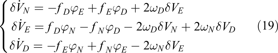
The velocity equations in the navigation frame are expressed as follows 6

After differentiating the above equations, we have

and 35
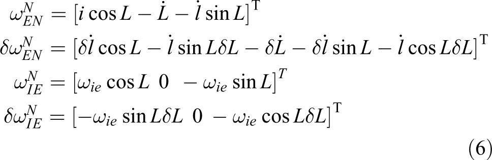
The following relations are obtained by expanding equation (5) and neglecting variations of g and elements containing the position error


where BJ s are the maps of the accelerometer errors on the navigation axis

Attitude is represented by the minimum number of parameters, which is three. These three parameters are the rotation vector components that describe the small-angle error from the true navigation frame to the calculated navigation frame on the navigation system computer. 38 We have
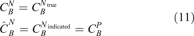
where P is the coordinate that will be used instead of N on the navigation system computer, and represents the arithmetic coordinate or the analytic stable plane. When the navigation system has an error in calculating the rotational attitude, the rotation vector from N to P is shown by ϕ. For a small ϕ we have

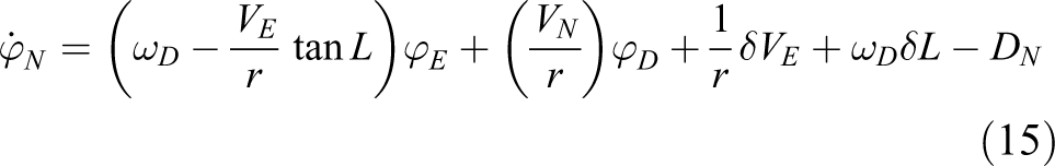
Besides, since ϕ values are small, they can provide good approximations of Euler angles between the P and N frames. As shown in the following, the resulting linearized differential equation for ϕ error vector is expressed as follows

and

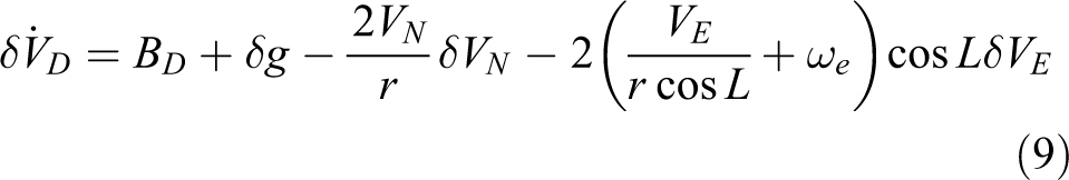
The true navigation coordinate (N) is considered an unknown coordinate, and thus the related rotation matrix and the velocity vector will have errors. The components of equation (13) after simplification are as follows

where

In case the navigation system is not moving in relation to the Earth, the error model is as follows
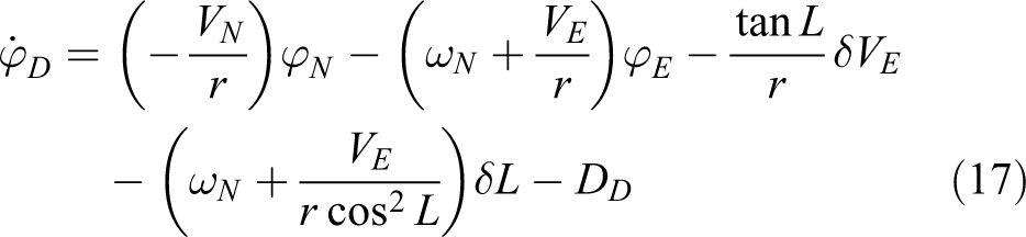
The angle error with the control signal feedback (

where
Remark 1
The heading angle convergent in equation (20) is very slow, since the Earth angular rate is too slow and the sensor noise is too large. To improve heading angle convergence, we employed a feedback from north velocity error with c gain. The c gain should be chosen in such a way that the heading convergence rate improves, but the heading angle noise must not be amplified. In practice, the estimated variance of the heading angle must be set as a big value to depress the sensor noise. If not, its convergent speed will be very low.
Remark 2
In this error model, we assumed that the gyroscopes do not have bias errors, or we accept the bias error of the gyroscope in the final error (due to the inability to observe the bias error of the gyroscope in general, in the problem of marine alignment). Equations (15) to (17) show that any bias in the sensors is manifested as an angle error, and this angle error exists until the bias is corrected, resulting in the error in the analytic stable plane. As a result, the error is mirrored in the accelerometers image and it causes a constant velocity error as shown by equation (19).
Kalman filter with control signal
Assume the system model includes the known control signal expressed as follows

where uk denotes the known control signal.
The structure of the Kalman filter algorithm in this case is shown in the following 39

Besides, Kk is calculated via the conventional Kalman filter equation. 39
Note that the introduction of the known control signal to the system model does not influence the calculation equations for the gain matrix Kk and only the a priori estimate of the state vector in equation (22) changes as follows

State-space model
As mentioned in the previous section, the space-state model is expressed via equation (21).
38
For Φ

For G

For u and C

The measurements used are the velocity error measurements that are entered into the filter along with the specified covariance matrix R

Matrix H is also as follows

SINS alignment algorithm
For increasing the rate of convergence to true heading, we combined the extended Kalman filter (EKF) with the improved error model. For this purpose, we utilized a control signal feedback from the north velocity error to change the SINS heading channel damping based on the traditional platform INS structure. For the error model presented in equation (20), the convergence rate of the roll and pitch is much greater than the heading convergence rate when the c gain is zero. We could improve the heading convergence rate by adjusting the value of the gain c. But it is necessary the north speed variation only depend on the heading changes. So, as gyrocompass alignment method, we create an analytic stable plane in the SINS structure, then north channel velocity residual error is used as the control signal feedback for the heading channel. The SINS structure with the control signal feedback EKF is depicted in Figure 1. In the proposed structure, the control signal feedback is not used for 25 s. Afterward, using the horizontally analytic platform plane, we start using the control signal feedback in EKF. After creating the horizontally analytic platform plane,
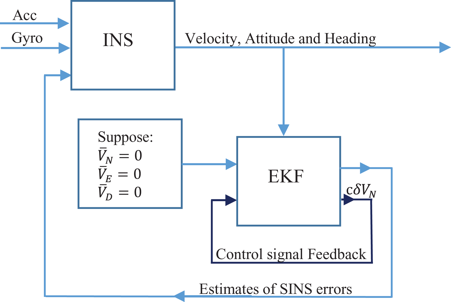
The SINS structure with control signal feedback and EKF. EKF: extended Kalman filter; SINS: strapdown inertial navigation system.
Simulation results
In this section, the simulation study shows the capability of the proposed algorithm to correct the initial heading error and confirm the performance under the marine mooring condition. Input data (accelerations and angular velocities) that fed to the algorithm were created using the relationships expressed in the next sections.
Sensor model
Table 1 presents the parameters of the IMU model used in our simulation.
Parameters values for IMU error model.
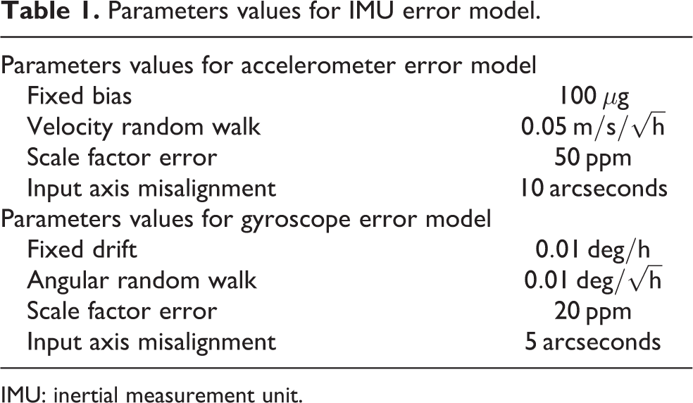
IMU: inertial measurement unit.
The relationship between true and actual IMU outputs can be expressed as follows


In the above equations,
Sea turbulence model
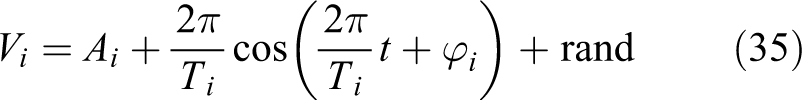
To simulate the designed algorithm, there is a need for a model of sea turbulence. Different models have been suggested for this purpose in different papers. In this section, the models in some papers are presented and one of them selected for use in this research. In the study by Scherzinger and Reid, 37 it is assumed that the ship is in an anchorage and the angles of its heading, pitch, and rolling are changed as follows

where ψ is the heading angle, θ is the pitch angle, and ϕ is the roll angle. Also, its velocity changes as follows

where

where
In the study by Sun and Sun, 20 it is assumed that the ship is in an anchor and the angles of its heading, pitch, and rolling are changed as follows

where ψ is the heading angle, θ is the pitch angle, and ϕ is the roll angle. Also, its velocity changes as follows
where
The authors 20 also provide a model that is almost the same as in the study by Gao. 30 In the study by Chang et al., 2 only the attitude model is pointed out. Because of the validation and completeness of simulation, the model proposed by Gu et al. 40 is used in this article for simulations. Of course, to evaluate and compare results with different conditions, the models presented in other references are also used. This is necessary to investigate the comprehensiveness of the algorithm under different perturbation conditions.
For simulation, the following parameters are considered for the filters:
The initial value of the state x 0 = 06×1.
The initial covariance of the state
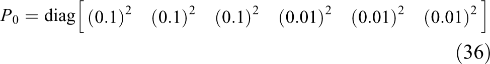
The values are represented in
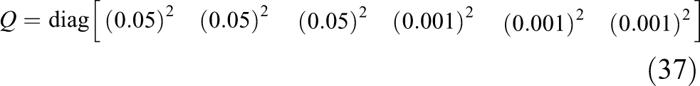
The values are represented in

Simulation results
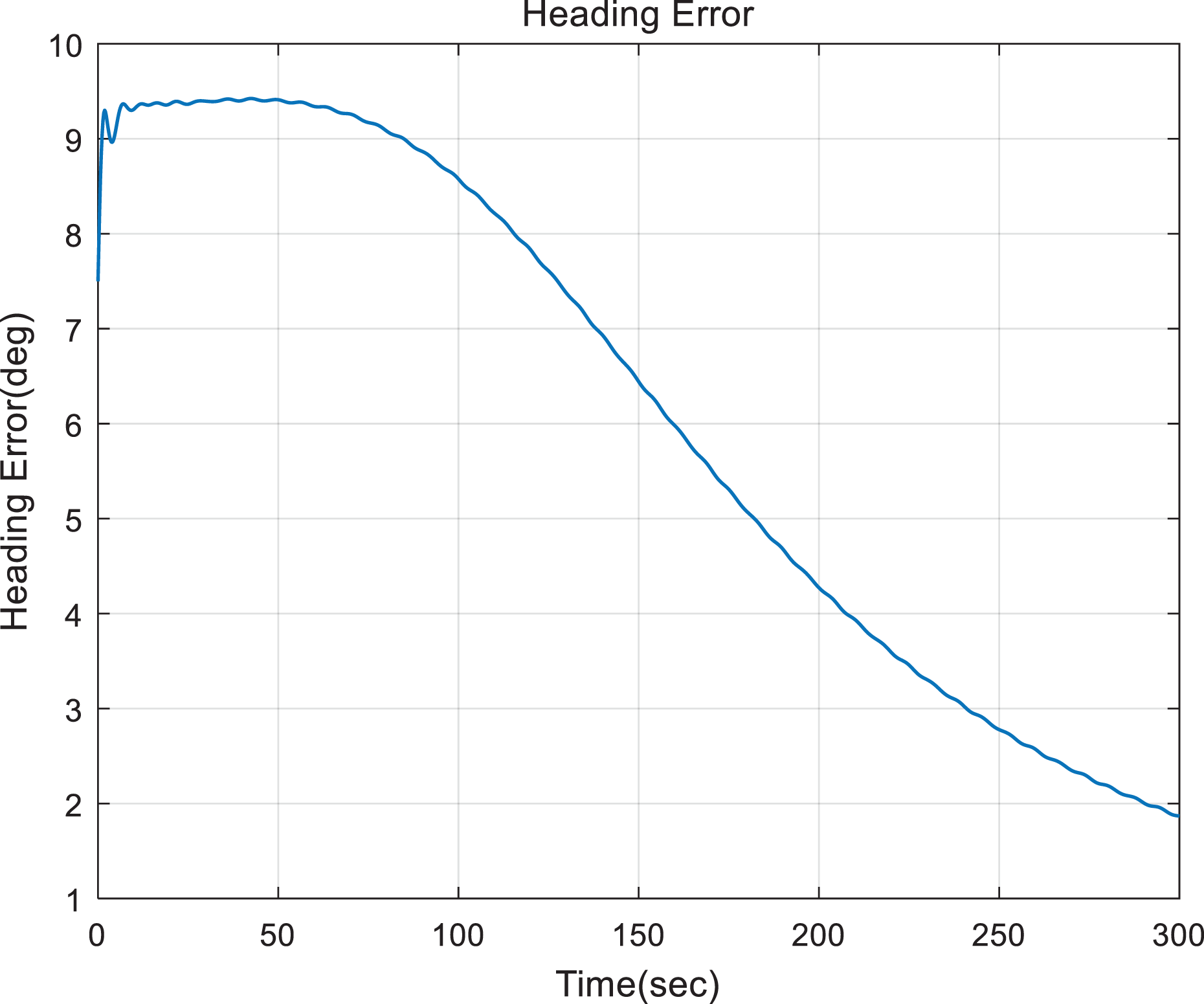
First, the data from the sea oscillation model are used to examine the results with the EKF without the heading measurement feedback error. In this case, we assume an initial heading error of approximately 10°, and filter functions for 300 s. Figures 2 to 4 illustrate the slow convergence behavior of the conventional method (without heading measurements). As seen in Figure 2, this process is repeated in the following in the presence of sea oscillations using the speed error in the north direction as the simulation error (Figures 5 to 7). In this case, the initial error is assumed to be at least 10°. As shown in Figure 6, convergence occurred in less than 60 s.
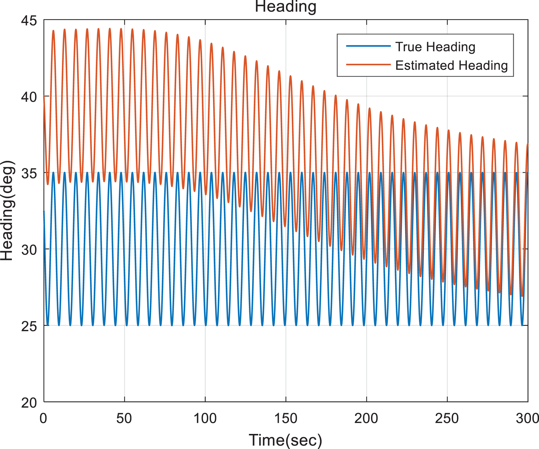
The heading angle estimation using the usual method (without using the heading error feedback).
The heading angle error using the usual method (without using the heading error feedback).

Roll and pitch angle errors with the usual method (without using the heading error feedback).

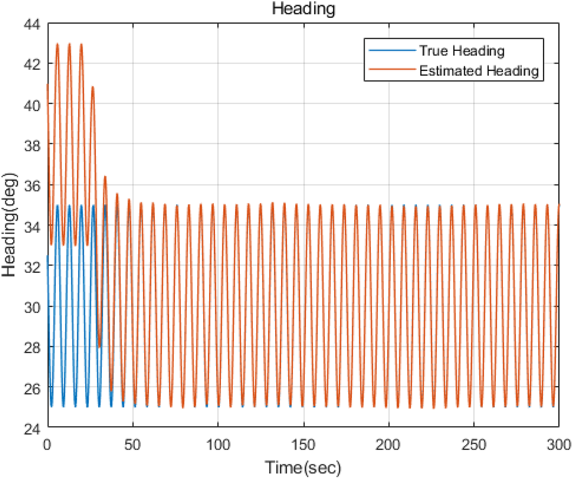
The heading angle estimation using the heading error feedback.

The heading angle error using the heading error feedback.
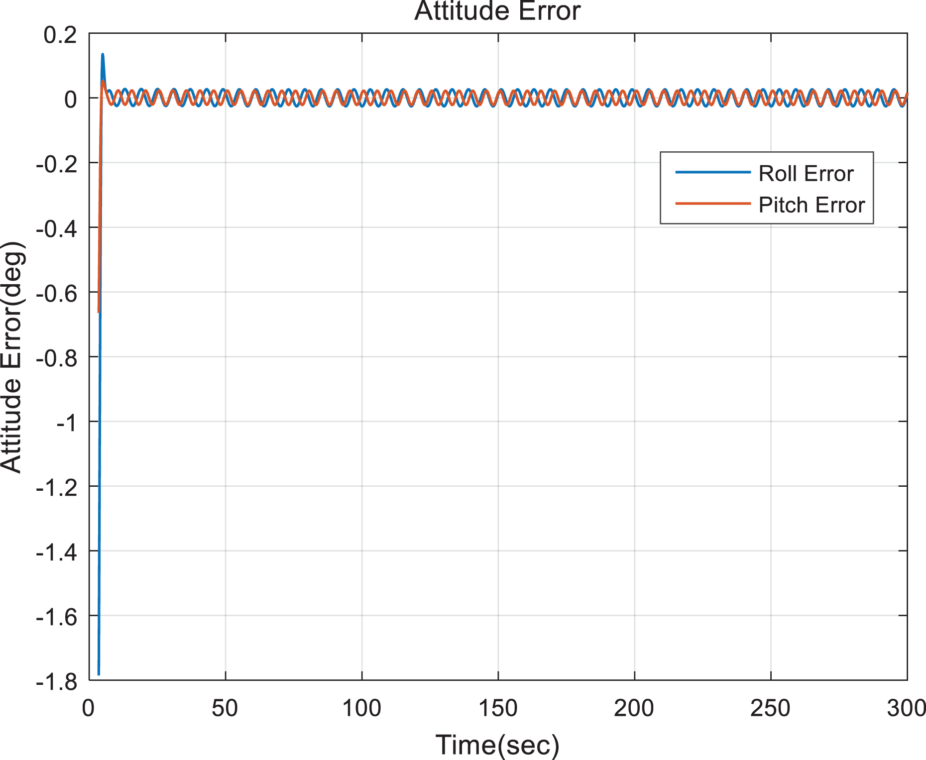
Roll and pitch angle errors using the heading error feedback.
It can be concluded from the simulation result that the proposed algorithm significantly increased the convergence speed which is important criteria for INSs. The reason is that the feedback from north velocity error improved error model dynamics.
Experiment results
We placed the fiber optic gyroscope (FOG)-IMU-based SINS which is produced by our laboratory on the two-axis turntable that can rotate along its vertical and latitudinal axis under the motor drive. The IMU is using accelerometers with a precision of 100 µg, and gyros with a precision of 0.01 deg/h. The IMU can be seen in Figure 8.

Self-made FOG-IMU. IMU: inertial measurement unit.
A turntable test is conducted to validate the performance of the alignment algorithm presented in this article. We run the turntable to simulate the mooring conditions. The data update rate is 400 Hz and we use 300 s data. The turntable performs the sinusoidal oscillation along its vertical and latitudinal axis under the motor drive. The oscillation period is 8 s and its magnitude is 10°. The initial level misalignment errors are set to be 10°. The filtering parameters for the filters are the same as in the fifth section. The roll, pitch, and heading angles with EKF and without the heading measurement feedback error are shown in Figures 9 to 11.

The heading angle estimation using the usual method (without using the heading error feedback).

The heading angle error using the usual method (without using the heading error feedback).

Roll and pitch angle errors with the usual method (without using heading error feedback).
The roll, pitch, and heading angles with EKF and with the heading measurement feedback error are presented in Figures 12 to 14.
The heading angle estimation using the heading error feedback.

The heading angle error using the heading error feedback.

Roll and pitch angle errors using the heading error feedback.
According to experimental tests, the proposed alignment method increased heading convergence under mooring conditions. Also it can be understood from results that the large heading angle error problem is solved well, therefore the proposed method does not require coarse alignment.
Conclusion
An improved alignment algorithm for marine SINS based on the control signal feedback in EKF was proposed in this article. The major improvement carried out in this work was meant to reduce the time of heading angle convergence in the mooring conditions alignment. In the proposed algorithm, the north velocity error in the analytic stable plane of SINS was used as a control signal damping feedback to heading error in EKF. The heading error is not directly available. However, the propagation error equations imply that after horizontal alignment of SINS analytical plane, the velocity error in the north direction is directly related to the error of the heading angle. This error can be entered into the filter as a control signal, accelerating the heading angle convergence. As regards the simulation and turntable test results, this algorithm significantly improved the convergence rate of the heading angle compared to the conventional methods.
Footnotes
Declaration of conflicting interests
The author(s) declared no potential conflicts of interest with respect to the research, authorship, and/or publication of this article.
Funding
The author(s) received no financial support for the research, authorship, and/or publication of this article.