
Abstract
Bending characteristics of double-walled pipe during offshore reel-lay operations have been investigated by finite element method. For the subsea pipeline reel-laying operations, the pipe is welded and spooled on the reel at docks. The pipe undergoes repetitive bending deformation while spooled on the reel. At the offshore destination, the pipeline installation is usually accomplished by spool-off, straightening, and laying out the pipelines. When the pipe is reeled out at sea, again it undergoes bending deformation. In order to simulate such a nonlinear behavior, the bending analysis of double-walled pipe consisting of SS400 and STS304 has been analyzed by finite element method and discussed for the respective cyclic bending processes using the relation of deformed compatibility of hysteresis loops. Furthermore, the feasibility analysis has also been made on the application of combined material properties which are based on the rule of mixture to the finite element analysis of double-walled pipe. The analysis results give a reasonable understanding of how materials behave during cyclic deformation of reel-laying operations. The application of combined material properties is proved to be feasible for the analysis of double-walled pipe with reasonable accuracy.
Introduction
Pipelines have been the primary mode of transporting liquids and gases in many practical applications such as offshore structures, platforms under severe weather conditions, and heat exchangers in power plants due to its reliable, economical, and convenient features. Single-walled pipes have been widely used in transportation because of their reliability, convenience, and economical manufacture. Although single-walled pipes have advantageous properties, they are difficult to inspect for safety, as well as monitoring if an accident was caused by the natural corrosion, wear, aging, or man-made destruction.1,2 In case of double-walled pipes, the outer pipe provides a safety measure by allowing time to take appropriate action whenever the inner pipe develops a leak. Thus, double-walled pipes provide greater reliability and can provide greater bursting resistance as compared to a single-walled pipe, so they are used widely for petrochemical plants, power generating facilities, and machine parts.3,4 With an increasing need for transporting corrosive fluids, there is an increasing demand for corrosion proof pipelines. However, the cost for pipelines of corrosion proof material has increased, and less expensive alternatives are therefore being sought after. One such less expensive alternative is a double-walled pipe which is generally composed of two metallic layers. A double-walled pipe typically comprises a load-bearing, thick-walled, outer pipe of high-strength carbon steel, lined with a thin-walled inner pipe of a corrosion-resistant alloy. The outer pipe resists buckling during spooling and unspooling and resists hydrostatic pressure when underwater. Conversely, the inner pipe provides relatively little mechanical strength, but it protects the outer pipe from corrosive constituents of fluids carried by the pipe in use. Double-walled pipes of a stainless steel inner pipe packaged with an outer pipe of carbon steel are used for the transport of corrosive liquids. Such pipes could prolong the life of a given assembly and save on material costs.5–7 Reel-lay method installs offshore pipeline by sending the pipeline from a reel mounted on a special pipeline installation vessel. Instead of connecting each joint of pipeline at an offshore location like other methods (S-lay and J-lay method), the pipeline is pre-assembled in a spool which is mounted on the deck of the reel barge, as shown in Figure 1.8–12 Pipeline is generally spooled onto the reel at docks. There, short lengths of pipe can be welded under protected and controlled environments to form a continuous pipeline which is spooled onto the reel. The lay barge is then moved to an offshore pipe laying location and the pipeline spooled off the reel between completion points.
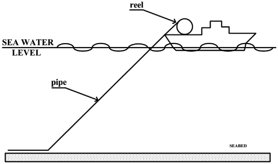
Schematic drawing of pipeline laying operation.
During the spooling on the reel, the pipeline undergoes large plastic deformation. While the pipeline leaves the reel, but before it enters the water, it is moved through a plurality of rollers so positioned and arranged as to reverse the bend which had been earlier imparted to the pipeline in order to wind it on the reel. The physical design of the reel and bending apparatus has been somewhat limited in that it is not readily adaptable to various operational conditions such as the depth of water and dimensional characteristics of the pipe. For example, pipe characterized by large diameter and thick walls is not easily bent toward an acute angle because the pairs of rollers applying forces to the pipeline would have to be disposed closely to one another and great forces applied to them.
This study relates particularly to reel-lay operations of mechanically lined double-walled pipe for laying subsea pipelines. Mechanically lined pipe (MLP) in which an interference fit between the inner pipe and the outer pipe fixes the inner pipe without metallurgical bonding. MLP benefits from an economical production process that makes it much less expensive than clad pipe. Double-walled pipes undergo continuous, longitudinally progressive plastic deformation during spooling procedures. Bending deformation of a pipe upon spooling develops considerable stresses and strains in the pipe wall, including ovalization in transverse cross section. Specifically, under bending deformation of mechanically lined double-walled pipe, the thick-walled outer pipe may be structurally stable or undergo slight ovalization, while the thin-walled inner pipe suffers significant deformation under the combined action of bending and external pressure from the outer pipe. This deformation manifests itself as buckling or wrinkling of the inner pipe, especially around the intrados of the pipe bend. A wrinkled inner pipe may hinder the smooth flow of fluids and may decrease fatigue life due to stress concentration.13,14 Metal structures which are subjected to cyclic loads must be strong enough to resist repeated loading of the material.15–17 It is important to understand the material behaviors responsible for their performance in service, in particular their cyclic deformation response. Parameters representing cyclic mechanical behavior can be obtained by determining characteristic features of stress–strain hysteresis loops such as the peak stress, the effective stress, and the loop shape parameter. The analysis of stress–strain hysteresis loops gives a reasonable understanding of how materials behave during cyclic deformation. 18 To enable subsequent bending, spooling a pipe onto a reel typically takes place in a domain between elasticity and pure plastic or rheological behavior. This typically involves a bending strain of 1%–5%. 19 Therefore, the simulation of bending deformation by finite element method (FEM) is very important to prevent winkles during reel-lay operations and estimate the capacity of reel and bending apparatus on vessels for the successful reel-laying operations. Therefore, in this study, the bending characteristics of double-walled pipe during offshore reel-lay operations have been investigated on the basis of stress–strain hysteresis loops. The feasibility analysis has also been performed for the application of combined material properties in the FE analysis of double-walled pipe which are based on the rule of mixture. For this, the stress–strain hysteresis loops obtained from FE analysis using combined material properties (so called, combined analysis) are compared with those using respective material properties (so called, separate analysis) of SS400 and STS304 pipes.
Feasibility analysis on applicability of mixture rule
Prior to performing the analysis on reel-laying operations, the feasibility analysis has been performed on the application of combined material properties which are based on the rule of mixture to the finite element analysis of double-walled pipe. Figure 2 schematically shows typical deformation modes during reel-laying operation. As shown in Figure 2, the pipeline suffers four successive deformations during reel-laying operations, such as bending–straightening–bending–straightening.

Four successive deformation during pipeline reel-laying operation: bending (during spooling)–straightening (spool off)–bending (at lay lamp head)–straightening (for laying).
Hence, it is important to understand the deformation behaviors responsible for their performance in service, in particular their cyclic deformation response. To analyze above-mentioned cyclic deformation behaviors, repeated tube bending and straightening process has been simulated as shown in Figure 3. A commercially available simulation software, ANSYS v12, was used for the cyclic bending simulation.

Schematic drawings of successive bending simulation: (a) bending, (b) straightening, (c) bending, and (d) straightening.
During the pipe bending, tensile stress is applied on the extrados of the bend and compressive stress on the intrados of the bend. Parameters representing cyclic mechanical behavior can be obtained by determining characteristic features of effective stress–effective strain hysteresis loops. Figure 4 shows shape of bending die used for FE analysis. The radius of bending die is equivalent to that of reel.

Die shape for FE simulation (unit: mm).
The pipe investigated in this study is double-walled pipe consisting of SS400 and STS304. The material properties of SS400 and STS304 are shown in Table 1.
Materials properties.
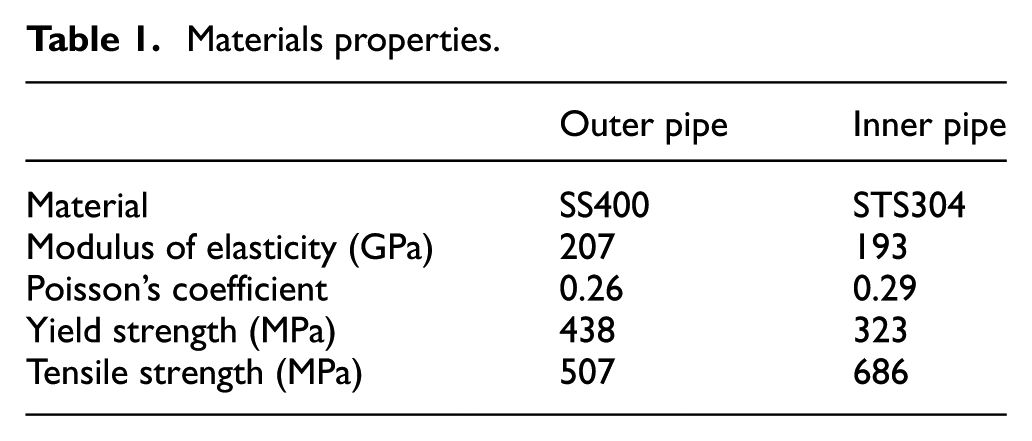
Two different material types are investigated in FE analysis of double-walled pipe. Figure 5(a) separates material type that shows double-walled pipe consisting of SS400 (outer) and STS304 (inner) having respective material properties shown in Table 1. Figure 5(b) shows combined material type that assumes hypothetic single-layered pipe having combined material properties based on the rule of mixture for SS400 and STS304 pipes.

Pipe material types: (a) separate analysis and (b) combined analysis (unit: mm).
For the combined material properties, the rule of mixture shown in equation (1) has been used
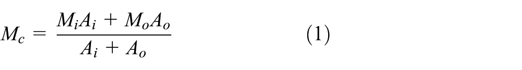
where “A” means cross-sectional area, “M” means material properties such as elastic modulus, Poisson’s ratio, yield stress, and tensile stress; and subscripts c, i, and o means combined, inner, and outer pipes, respectively.
Table 2 shows the combined material properties obtained from equation (1) with respective material properties described in Table 1. The stress–strain hysteresis loops obtained by FE analyses using two different material types are compared and discussed about feasibility.
Combined material properties based on SS400 and STS304.

Figure 6 shows the stress–strain measuring positions after cyclic bending process. During the pipe bending and straightening, the stress–strain states applied on the extrados of the bend (A) and those on the intrados of the bend (B) vary with instantaneous deformation.
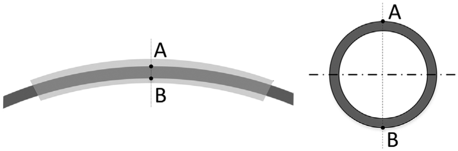
Stress–strain measuring positions after cyclic bending process.
Deformation behaviors of single-layered tube
FE analysis for respective pipe has been performed to investigate deformation behaviors of SS400 and STS304 single pipes having dimensions shown in Figure 5(a). The effective stress–strain variations of the pipes were measured at positions “A” and “B” shown in Figure 6 for the respective cyclic process. Figure 7(a) shows the stress–strain hysteresis loops obtained on the assumption of SS400 single-layered tube having dimensions of double-layered tube. It can be seen that the values of effective stress and strain were in the range of 437–501 MPa and 0.0026–0.023, respectively. Figure 7(b) shows the stress–strain hysteresis loops under same conditions for STS304 single-layered tube having dimensions of double-layered tube. The values of effective stress and strain were in the range of 366–468 MPa and 0.0004–0.0252, respectively. Clearly, the stress–strain curve response exhibits hysteresis due to repeated yielding of the material. The progressive enlargement of the stress carrying capacity of the pipe was also noted. When the pipes are deformed plastically at which cyclic bending occurs, the strength increases due to the work hardening. SS400 was cyclically hardened more than STS304 due to the thicker thickness and larger diameter of the circular pipe, and a higher magnitude of the bending stress was needed to bend the pipe into the desired curvature.
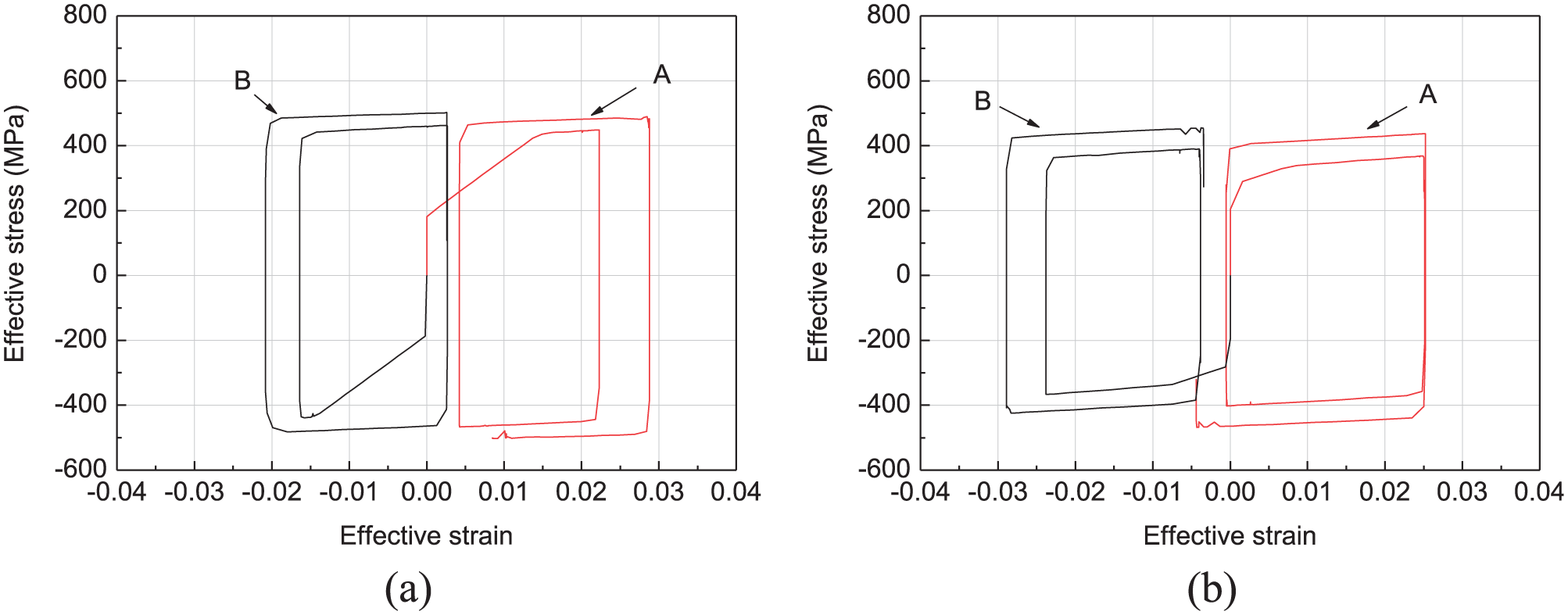
The stress–strain hysteresis loops of a strain finite element model under cyclic bending conditions: (a) SS400 and (b) STS304.
Comparison of deformation behaviors between separate and combined analyses
Table 3 shows the stress–strain values of cyclic bending process for the double-walled pipe having respective material properties of SS400 and STS304 (separate) and the single pipe having equivalent dimensions with double-walled pipe with combined material properties (combined). It can be seen that the values of effective stress and strain were in the range of 402–488 MPa, 0.00104–0.0235 and 391–476 MPa, 0.0017–0.0231 for the separate and the combined analyses, respectively.
Results of cyclic bending process for the separate and the combined analyses.

Figure 8 compares stress–strain hysteresis loops under same conditions for the separate and the combined analyses. As shown in Figure 8, the stress and strain are increased through the cyclic bending process. It is apparent that a reasonable agreement exists between the separate and the combined analyses. As a result, the substitution of double-walled pipe with hypothetical single pipe having combined material properties based on the rule of mixture is an acceptable alternative for the fast and easy FEM analysis of double-walled pipe.

The stress–strain hysteresis loops for the separate and the combined analyses.
Finite element simulation of reel-laying cyclic bending
To understand the deformation behaviors during reel-laying process, FE analysis has been performed for four successive deformation during pipeline reel-laying operation: bending (during spooling)–straightening (spool off)–bending (at lay lamp head)–straightening (for laying).
Figure 9 shows shape of bending die used for FE analysis. The radius of bending die is equivalent to that of reel.
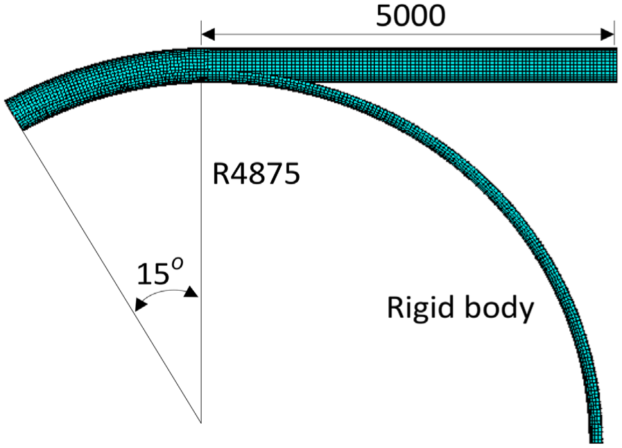
Die shape for FE simulation (unit: mm).
Figure 10 shows schematic drawings of successive bending simulation simulated in FE analysis: (a) bending, (b) straightening, (c) bending, and (d) straightening.

Schematic drawings of successive bending simulation: (a) bending, (b) straightening, (c) bending, and (d) straightening.
Deformation condition consists of bending (0–15 s), straightening (15–30 s), bending (30–45 s), and straightening (45–60 s) and total cycle time was 60 s. The extrados of the pipe and the bending die are in contact during pipe bending. The extrados surface of the pipe was modeled on the flexible contact body modeled using a three-dimensional (3D) contact element (Contact 174), and bending die was modeled on the rigid body using a 3D target element (Target 170). The pipe was modeled using an eight-node hexahedral 3D solid element (Solid 185) which is generally used in conditions of large deformation and elastoplastic analysis. The movement of pipe was controlled by displacement. Additionally, a Coulomb friction model with a 0.01 friction coefficient was used. The FEM commercial software ANSYS v12 was used to predict the bending process of pipe. The APDL was used to automatically generate the finite element bending models. The pipe and bending die were modeled with half geometry due to symmetry.
During the pipe bending, tensile stress is applied on the extrados of the bend and compressive stress on the intrados of the bend. Parameters representing cyclic mechanical behavior can be obtained by determining characteristic features of effective stress-effective strain hysteresis loops.
The stress–strain after cyclic bending process has been measured at four positions shown in Figure 11. During the pipe bending and straightening, the stress–strain states applied on the extrados of the bend (points 1 and 2) and those on the intrados of the bend (points 3 and 4) vary with instantaneous deformation.

Stress–strain measuring positions after cyclic bending process.
Results and discussion
FE analysis with two different material types has been performed to investigate deformation behaviors of walled pipe having dimensions shown in Figure 5. The effective stress–strain variations of the pipes were measured at positions shown in Figure 11 for the respective cyclic process.
Figure 12(a) and (b) shows the strain variations with separate and combined analyses, respectively. The values of effective strain by separate analysis were in the range of –0.0489 to 0.0491. The strain variations under same conditions and the values by combined analysis were in the range of –0.0487 to 0.0490. It can be seen that strain variations acquired by each analysis method agree well.

The strain variations for analysis method under cyclic bending conditions: (a) the separate analysis and (b) the combined analysis.
Figure 13(a)–(d) shows the stress variations at each measuring point. At points 1 and 2 on the extrados of the bend, tension–compression–tension–compression cycles were observed. Points 3 and 4 on the intrados of the bend show reverse tendency. The values of effective stress acquired at points 1 and 4 by separate analysis were similar to those by combined analysis, respectively. At points 2 and 3, when the process time was 0–6 s or 40–45 s, the absolute values of stresses by separate analysis was lower than those of combined analysis. Yield strength of inner pipe, outer pipe and combined pipe were 323, 438, and 410 MPa, respectively. As the yield strength of inner pipe is lower than outer pipe, deformation starts at lower stress state. The relatively larger differences between separate and combined analyses at points 2 and 3 can be explained by positions of measuring point that lies at inner pipe.

The stress variations for the separate and the combined analyses: (a) point 1, (b) point 2, (c) point 3, and (d) point 4.
Figure 14(a) and (b) shows stress–strain hysteresis loops under same conditions for the separate and the combined analyses. Except the difference of yield stress, the stress–strain hysteresis loops for the separate and the combined analyses match well during cyclic bending process.
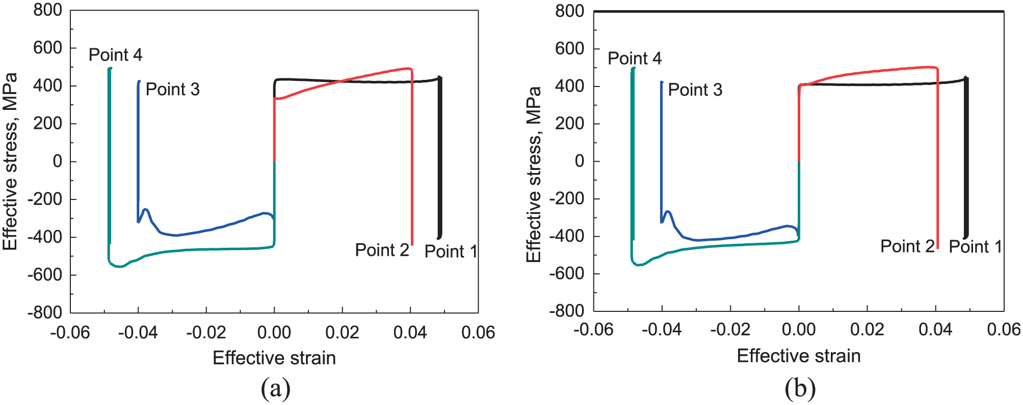
The stress–strain hysteresis loops for (a) the separate analysis and (b) the combined analysis.
Tables 4 and 5 summarize the FE simulation results of cyclic processes obtained from separate and combined analyses, respectively. It can be seen that the values of effective stress and strain were in the range of 210–493 MPa, 0.0396–0.0490 and 230–499 MPa, 0.0399–0.0493 for the separate and the combined analyses, respectively.
Results of cyclic bending process for the separate analysis.

Results of cyclic bending process for the combined analysis.

As stated before, the bending strain of 1%–5% is desirable for successful spooling of pipe onto a reel. The obtained strain values lie within this recommended range. It gives a reasonable understanding of how materials behave and the ranges of effective stress–strain during cyclic deformation of reel-laying operations. And, it is apparent that a reasonable agreement exists between the separate and the combined analyses. It confirms that a hypothetical single pipe having combined material properties is feasible alternative for the analysis of double-walled pipe.
Conclusion
Bending characteristics of double-walled pipe consisting of SS400 and STS304 during offshore reel-lay operations have been successfully analyzed by FEM and following conclusions are obtained:
It gives a reasonable understanding of how materials behave and the ranges of effective stress–strain during cyclic deformation of reel-laying operations.
It confirms that a substitution of double-walled pipe with hypothetical single pipe having combined material properties based on the rule of mixture is a feasible alternative for the FEM analysis of double-walled pipe at a significantly reduced simulation time without boundary contact problems between inner and outer pipes
On the basis of effective strain ranges of combined and separate material analyses, the possibility of successful spooling of pipe onto a reel can be estimated prior to actual operation. The bending strain of 1%–5% is desirable for successful spooling of pipe onto a reel.
Footnotes
Handling Editor: Yi Wang
Declaration of conflicting interests
The author(s) declared no potential conflicts of interest with respect to the research, authorship, and/or publication of this article.
Funding
The author(s) disclosed receipt of the following financial support for the research, authorship, and/or publication of this article: This work was supported by the National Research Foundation of Korea (NRF) grant, which was funded by the Korean Government (MSIP; no. 2012R1A5A1048294).