
Abstract
Gait planning is an effective approach aiming at the difficulty in locomotion control of a multi-degree-of-freedom snake-like robot. In this article, a gait-generating method is presented with regard to the issue of its locomotion control in the process of winding–crossing variable-diameter cylindrical obstacles involving a P-R-joint scale-driven snake-like robot. The proposed method solves the problem of trajectory discontinuity of variable-diameter helix lines through linear fitting in the process of the obstacle crossing of the robot. The collision/interference between the robot and the obstacle is avoided by adding an extended helix segment to the front and rear ends of the obstacle. For direct linear fitting of the locomotion trajectory curve that will lead to velocity discontinuity, B-spline curves are used for smooth transition on generating the trajectory curve. A simulation experiment analysis is performed to demonstrate that the proposed gait-generating method can enable the snake-like robot to cross variable-diameter cylindrical obstacles.
Introduction
Research on the application of snake-like robot in the fields of medical treatment, emergency rescue, and outer space exploration is active due to its flexible control method and special structural style. Most research on snake-like robots is related to ground and underwater environments.1–3 However, a relatively small number of studies on snake-like climbing robots, which can be divided into inner-climbing and outer-climbing types, have been conducted.4–6 The outer-climbing type, as the current focus of research, is operating on the outer wall of cylinder tube to fulfill the climbing motion by winding. Nonetheless, the multiple degrees of freedom of snake-like robots would render the difficulty in inverse kinematic solution. Gait planning is an effective mean to realize the locomotion control of the robots. 7
The outer-climbing type of snake-like robot mainly climbs accessible cylinders. Hatton and Choset 8 from the Carnegie Mellon University studied the adjacent units of a type of outer-climbing snake-like robot, which were linked using orthogonal deflection joints, and Choset used modal decomposition to modify the side-winding gait of a snake robot to orient the head in the locomotion. Cappo et al. 9 also came up with two gait algorithms, namely, annealed chain fitting and keyframe wave extraction, to realize a snake robot climbing a pipe. Lu et al. 10 proposed cyclic inhibitory central pattern generator method. Islam and Chen 11 proposed a novel natural gait for multi-link mechanical systems. Melo and Paez 12 analyzed different gaits for different sizes of horizontal pipes, which mainly used the rolling method for locomotion. Liljeback et al. 13 presented a control framework for shape control of a snake robot based on specification and the desired shape of the snake robot, as a continuous shape curve defined by a set of shape control points interconnected by Bezier curves. Kamegawa et al. 14 studied a snake-like robot climbing upright pipes with moving wheels. Tanev et al. 15 studied the method of outer climbing. Suzuki et al. 16 studied the method to control the tree climbing of a snake-like robot. The South China University of Technology studied a snake-like robot for bridge cable detection. 17 The Shanghai Jiao Tong University proposed a type of outer-climbing snake-like robot based on P-R module. 18 This type of robot took an inchworm-like locomotion gait to finish the climb by transmitting the kinematic wave from tail to head, where its climbing trajectory was always based on isometric helix.
Vespignani et al. 19 explored whether an optimal stiffness existed for gait, terrain type, or several gaits and several terrains and tested two locomotion gaits (rolling and side-winding) of a snake-like robot over flat ground and three different types of rough terrains. The above climbing robots of various types can climb along cylindrical structures without obstacles and different types of rough terrains, while limited attention has been paid to climbing motion along cylindrical structures with obstacles.
In biosphere, tree snakes can climb various tree trunks with prominence by virtue of their own ventral scales. The ventral scales have backstop characteristics resembling ratchet mechanisms, namely, the friction along the forward direction is low, whereas the friction backward is high. The ventral scales under the muscle slide back and forth relative to the bone, thereby providing a driving force for the tree snake to proceed.
A snake-like robot is made up of a plurality of units in series with a specific joint, and various movements are realized by the coordinated control of each joint. The ideal movement of snake-like robot is similar to that of a biological snake in nature. The snake-like robots are hoped to flexibly adjust the joint movement to achieve efficient exercise according to environment. However, owing to the high redundancy of the structure of the snake-like robots, their control is complex, and the flexibility of biological snakes could not be realized. Therefore, the most reasonable way is to imitate the movement of biological snakes in different environments, and some commonly used gaits are designed according to the structure of snake robots. Different gaits are switched according to different environments to achieve a control purpose. Gray 20 began the study of snake gait. Later, Professor Hirose from the Tokyo Institute of Technology in Japan developed a solid snake-like robot, studied the gait law of the snake-like robot on the basis of a large number of experiments, realized the winding movement of the snake-like robot, and carried on the mathematical description. Since then, many research institutions and scholars have begun to study snake-like robots and the gait generation of snake-like robots for each prototype in the world.
Research institutions have proposed various gait generation methods, which are mainly classified into three forms. Using experience and a large number of experiments as basis, the first form is to find the control function of the joint angle when the snake-like robot does some movement to complete the gait design. The snake-like robot can achieve meandering movement, lateral movement, and spiral winding motion in this way.21–23 The second form is to determine the curve of the snake-like robot body based on the operating environment of the robot, then the snake-like robot fits the curve for each unit. Finally, the movement law of the robot joint driver is determined through kinematic calculation and thus a robot gait is formed. 24 This method is suitable for the robot to run in a certain environment, and the process of computing is often complex. The third form is the path-tracking control algorithm, 25 with which the robot can automatically avoid obstacles. The approach is generally used in the case of unknown working environment.
The aforementioned three methods of gait generation are mostly used for ground-walking snake-like robots and external climbing snake-like robots, but present studies are mainly in the case of barrier-free climbing along a cylinder. In the case of variable-diameter obstacles, the walking process of robot is to wind a cylindrical rod (hereinafter referred to as the straight line) and a cylindrical obstacle (hereinafter referred to as the obstacle section) in a spiral thread with equal pitch. Given their different diameters, the robot needs to change the spiral radius of the winding in the obstacle crossing process. The part connecting the two sections of the pitch spiral curve is the transition curve. When the robot needs to cross the cylindrical obstacle, in fact, the robot changes from a spiral winding way into another spiral winding way. Therefore, the transition curve is introduced in this study. The effect of the transition curve is to connect two equal pitch spiral curves. When the robot fits the path from the equal pitch curve into the transition curve and enters the helix from the transition curve, the robot body and the wound cylinder are supposed to have no interference. The position and velocity of each joint change continuously during the whole movement of the robot.
This study proposes a scale-driven snake-like robot, which imitates the climbing mechanism of tree snakes, using a structural style to combine the active joint and active skin of tree snakes. A gait-generating method is introduced, and the principle of locomotion trajectory curve fitting is followed for climbing cylindrical structures with obstacles. This study proposes a new snake-like robot structure based on P-R-S module according to the P-P-R snake-like robot and the P-R snake-like robot developed by the Shanghai Jiao Tong University. Each P-R-S module unit has three degrees of freedom: roll, yaw, and translation. This snake-like robot not only has the advantages of forward action and gesture change action without motion coupling of the scale-driven snake-like robot and the capability of crossing barrier but also has the advantages of large working space of the P-R module snake-like robot.
This study is conducted from three aspects: (1) to propose a type of gait planning to fulfill winding locomotion and smooth transition of variable diameter, thus avoiding collision and interference between the robot and the obstacles; (2) to analyze whether any singular configuration exists when the robot is operating by this gait planning to avoid occurrence of fast and discontinuous change in the joint speed; and (3) to consider whether tangential relative motion is generated on the contact point between the robot unit and the obstacle in the process of crossing obstacle because this locomotion would cause the scale sleeve to produce lateral sliding friction, thus increasing energy consumption.
Robot mechanism and its mathematical model
Robot mechanism and obstacle crossing mechanism
As shown in Figure 1(a), the snake-like robot is composed of some units with the same structure connected from beginning to end. The robot structure is shown in Figure 1(b), where each unit has three kinematic pairs, that is, the yaw, roll, and translational joints. The yaw and roll joints can change the robot posture, and the translational joint is available for imitating the sliding motion mechanism of the ventral scales of a natural snake relative to skeleton to move forward. Some pressure sensors and an acceleration sensor are set in each unit module of the robot. The models are FSR402 and MPU6050, respectively. The positive pressure

Robot and structure sketch of the robot unit: (a) scale-driven snake-like robot and (b) structure sketch of robot unit.
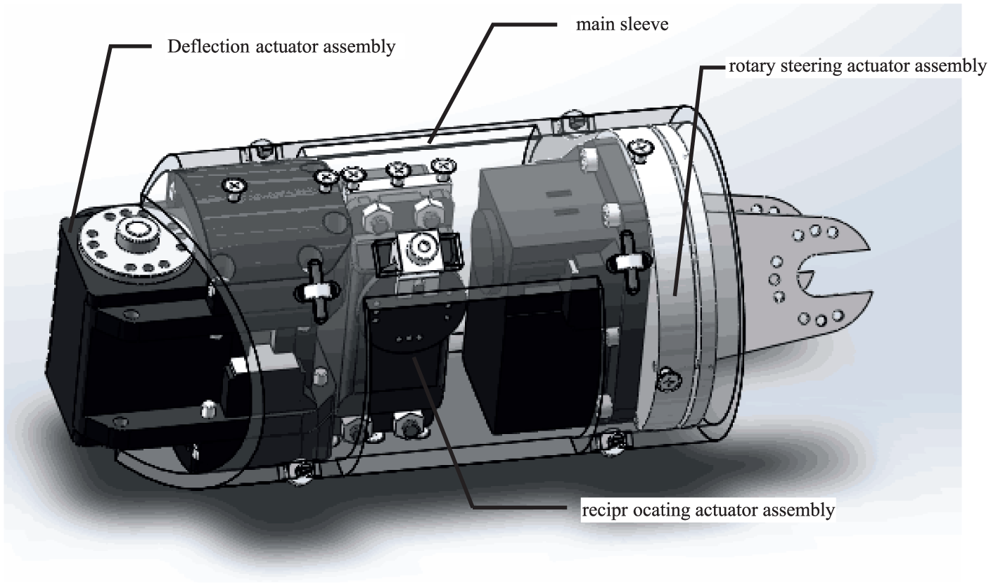
The body structure of the snake-like robot is shown in Figure 2. The robot main structural member includes a deflecting steering gear assembly, a reciprocating steering gear assembly, a rotary steering gear assembly, a main sleeve, and a scale sleeve. The main and scale sleeves are connected by rolling bearings. The main sleeve is the tubular main structure of the robot unit, with the function of contour support and internal mechanism positioning, and all the movement mechanisms are relative to the main sleeve movement.

Snake-like robot unit.
As shown in Figure 3, the main sleeve is equipped with a deflection actuator assembly, a reciprocating actuator assembly, and a rotary steering actuator assembly. The deflecting actuator assembly comprises an actuator and a supporting flange, and the flange and the output shaft of the deflection actuator are fixedly connected.
Structure sketch of main sleeve.
Figure 4 shows that the rotary steering actuator assembly includes a steering actuator and external gears fixed on the output shaft of the steering actuator, an internal gear associated with the external gear, a support that is rotatable relative to the internal gear, and a flange connector fixedly connected to an internal gear. The flange connector of the internal gear is connected to the flange in the adjacent unit of the deflection actuator assembly. Therefore, the rotary motion can be realized when the rotary actuator rotates, and the deflection movement can be realized when the deflection actuator rotates.
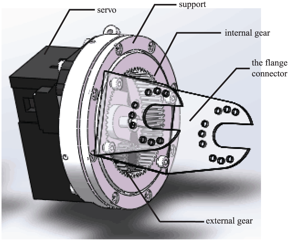
Structure sketch of rotary steering gear assembly.
The scale sleeve is coaxial with the main sleeve, its inner wall is smooth, and the outer wall is arranged with a number of scales. These scales are fixed on the scale sleeve, with small friction in the forward direction and greater friction in the opposite direction. As shown in Figure 5, considering that the cylinder surface has certain surface roughness and assuming that the cylinder surface is a ridge-like projection and groove with a certain regular shape, the scales of the snake-like robot and the projections and grooves of the cylinder surface constitute a ratchet mechanism. In the forward direction, the friction between the scales and the cylinder surface is small, and in the backward direction, the friction between the robot scales and the cylinder surface is large, which result in the asymmetry friction between the robot and the cylinder surface.

Robot forward process: (a) start state, (b) odd unit forward, (c) even unit forward, and (d) all units move one step.
The scale sleeve is connected to the reciprocating actuator assembly fixed in the main sleeve, which moves back and forth relative to the main sleeve with the force of the reciprocating actuator to provide the driving force for the robot. The robot should avoid the lateral sliding friction as much as possible during operation due to the large lateral friction of scale sleeve. As shown in Figure 5, the scale sleeve is simplified as a scale, the robot is deployed in the spiral direction, and the robot moves a step. In Figure 5(a), the starting state of the robot is that all the scale sleeves of the robot move to the end of the sleeve. The robot progress can be broken down into the following steps:
Step 1. The scale sleeve of the odd number unit moves forward to the beginning, as shown in Figure 5(b). At this time, the odd element scale sleeve gets backward dynamic friction, and the robot has a tendency to move backward. However, by forward static friction force of the even scale sleeve, the robot stays still.
Step 2. The scale sleeve of the robot number evenly moves forward to the beginning. As shown in Figure 5(c), the even scale sleeve gets backward dynamic friction, and the robot has a backward movement tendency. Nevertheless, the robot remains still under the forward static friction force of the odd scale sleeve.
Step 3. As shown in Figure 5(d), all the scale sleeves of the robot are moved to the end. All the scale sleeves get forward friction, and the robot body moves forward one step.
Steps 1–3 are repeated to continually move the robot forward.
Overturning moment is an external moment that the snake-like robot needs to overcome in the climbing process, which has an important effect on crossing the cylindrical obstacle. The overturning moment is related to the number of units of the snake-like robot. The common gesture of the snake-like robot is equidistant spirally wound, and the mathematical model of the overturning moment of the snake-like robot is established for the snake-like robot to maintain the equidistant spiral winding attitude, as shown in Figure 6. In the figure,
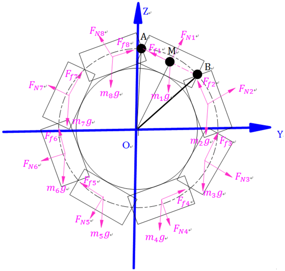
Calculation model of overturning moment.
The number of snake-like robots is N. Figure 6 implies that the overturning moment of the snake-like robot is

where

while
Each unit module of the robot has three degrees of freedom. N − 1 roll and yaw joints exist for the robot. N translational joints exist. The degree-of-freedom calculation shows that the degree of freedom of the robot is N + 2.
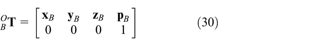
Coordinate systems should be fixed on each joint of the snake-like robot, and the relationship among these coordinate systems should be described to study the spatial geometric relationship among the snake-like robot units and because the motion of the joint causes the geometrical relationship among the robot units to change. Coordinate systems are typically established with the Denavit–Hartenberg (D-H) method, which can describe almost any type of body movement relationship. The spatial description of the robot unit relative to the environmental coordinate system includes a description of position and attitude. We first need to specify a fixed coordinate system to describe the position of the rigid body. In this study, the environment coordinate system is {0}. Relative to the coordinate system, the point position can be expressed in a three-dimensional (3D) column vector, and the rigid body posture can be expressed in 3 × 3 rotation matrix. The homogeneous transformation matrix is a 4 × 4 matrix that can be used to describe the position and attitude of the rigid body. We take the D-H method to build such coordinates, as shown in Figure 1(b), where inertial coordinate system


where
The robot and its mode of motion are shown in Figure 7, according to which the robot will move on the surface of cylindrical shaft along the radial direction by helix winding. The diameters of different segments of such cylindrical shaft vary. Figure 8 depicts that the obstacle diameter is greater than the line diameter on its two sides. However, the material and surface properties of the line and obstacle segments are the same. The robot needs to change the helix radius of winding motion to cross the variable-diameter obstacle. The strategy to change helix radius is critical to gait generation in the obstacle crossing process.

Snake-like robot crossing an obstacle.
Schematic of robot winding gait.
The snake-like robot has two patterns of motion. The first pattern is the single-diameter cylinder pattern of motion; for example, on the operational phase of line and the operational phase of obstacle, the helix diameter of the robot winding motion would not change. The second pattern is the variable-diameter cylinder pattern of motion; for example, in the transformation from line1 to obstacle or from obstacle to line2, the helix diameter of the robot winding motion would change.
Under the second pattern of motion, as the robot moves from line to obstacle, the cylinder radius will increase mutationally and the helix radius of the robot locomotion trajectory, thus resulting in impact among joints of the robot. Therefore, transitional treatment should be performed on the mutational point of helix radius. This article discusses the method of segmenting helix of polygonal approximation for transitional treatment, thus generating the gait of obstacle crossing.
Equation of isometric helix
Under the first pattern of motion (equal-diameter cylinder), the robot will wind the cylinder with the posture of isometric helix, and its projection on the axial direction of cylinder is shown in Figure 9. Supposing that the cylinder radius is

Robot posture on axial direction.
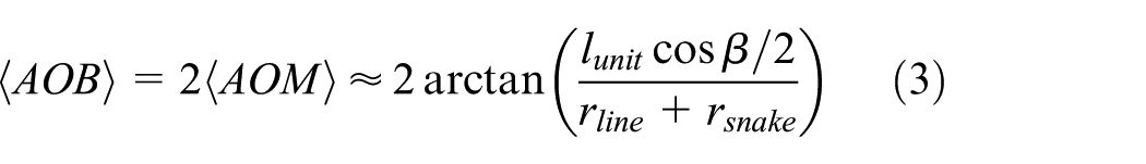
Given that the robot unit is tangent to the cylinder winded, seen from the axial direction, the triangle
where

where
When the robot is running on the obstacle, substituting
Transition curve
Under the second pattern of locomotion, the helix curve of the robot winding motion should be treated, and the role of transition curve is to connect two sections of isometric helix curves. For convenience of description, the robot winding posture will be unfolded along the helix direction, as shown in Figure 10. The dashed line represents the planned pre-tracking trajectory. The robot will perform polyline fitting along the planned trajectory in dashed line to obtain the winding pose of the entire robot.

Schematic of robot crossing an obstacle in the helix unfold direction.
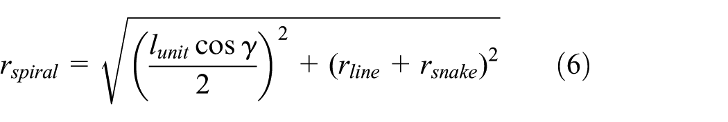
The essence of obstacle crossing is to enable the robot to shift from one pattern of spiral winding to another. Supposing that the robot winds cylinders of different diameters, the helix angles “
We suppose that the location of obstacle is from


Polyline trajectory in the helix unfold direction.
The plan of locomotion trajectory can be divided into the following portions:
The line prior to obstacle crossing

The obstacle and the extended segment

where

The line after obstacle crossing

where

The transition segment prior to obstacle crossing

Therefore

where


The transition segment after obstacle crossing

Thus

where


Generation of robot gait for obstacle crossing
The generation of robot gait for obstacle crossing is based on locomotion trajectory, which is the solution of pose parameters in the robot locomotion process. The axis position of each unit and the joint angle in the robot locomotion trajectory are first solved, and
Seeking the nodes of polylines
If the ideal trajectory curve is known, the following steps shall be taken to calculate the nodes of polylines:
One initial point is sought on the ideal trajectory line, where
We suppose that
If
As aforesaid, the position of each robot joint can be found in turn.
Calculation of the joint angle of robot
Once the position of unit axis is found, the angle of each robot joint can be calculated on the basis of such position parameters. This study proposes an analytical method to calculate the joint angle. In Figure 12,

Robot coordinates.
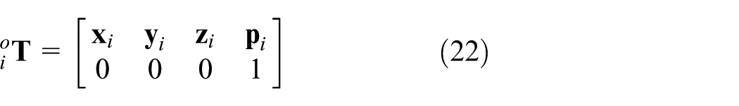
The transformation matrix of inertial coordinate system
and

Therefore
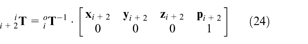
and the transformation matrix among the nodes of the robot is

where

The axes of

where

From equations (26) and (28), the first columns in the matrix on the right of both equations are equal to each other; thus, the following equation can be obtained

The deflection and revolution angles of unit
Determination of B coordinate system
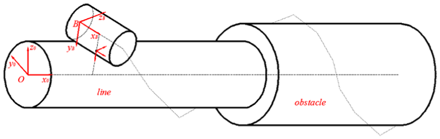
In the processes of winding and obstacle crossing, some units of the robot and the cylinder winded will be tangent, as shown in Figure 13. Supposing that the axis of such a unit is

Diagram when robot winding on a cylinder pipe.
The special structure of the used scale sleeve limits the robot motion on
Before determining whether a lateral movement velocity exists in each unit, ensuring that the terminal unit of the robot has no lateral movement velocity
Supposing that the pose of inertial coordinate system relative to the terminal unit is
and

The direction of

Therefore

The orthogonal coordinate relation presents that

When terminal B is on the line

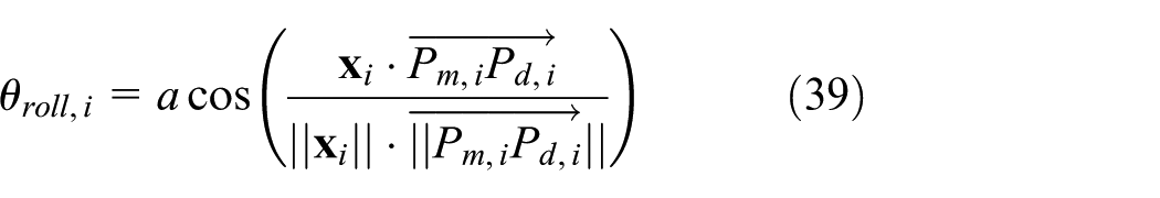
Calculation of rollover deviation angle
The rollover deviation angle of another unit shall be calculated. We suppose that the transformation of inertial coordinates relative to the coordinates of any unit
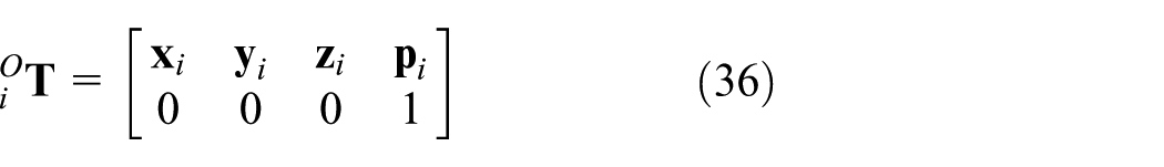
where

Accordingly

The rollover deviation angle is
Simulation experiment of obstacle crossing process
The purpose of this experiment is to study the obstacle crossing process, that is, (1) whether adjustment of each joint pose can enable the robot to roll along its own axis, thus resulting in lateral friction force; and (2) whether the robot has a strange configuration in the process of crossing obstacles, thereby resulting in significantly large or discontinuous joint speed. When the robot moves forward, the base system {B} moves along the ideal trajectory curve. To study the entire process of the crossing obstacle of the robot is to study the movement of the base system {B} along the trajectory curve.
This experiment is conducted by simulation in the environment of MATLAB 2010b, and the parameters of which are shown in Table 1.
Simulation parameters.

The procedures of the simulation experiment are detailed as follows:
The mathematical expression of the trajectory is obtained by the calculation method of the robot joint pose proposed in section “Generation of robot gait for obstacle crossing.” The initial helix angle
The node coordinates of each polyline are calculated with the method to seek isometric polylines.
Pose
Supposing
Supposing the initial angle of point B:
The final status of the robot winding obtained from the simulation experiment is shown in Figure 14, where “*” represents the nodes of theoretical polylines, and “o” represents the node of each joint obtained from the simulation calculation. In the process of the robot forward motion, the coordinate trajectory of point B is shown in the left of the Figure, where the red section represents axis A, the blue section represents axis

Using polyline to fit the trajectory curve (final status).
When point B on the terminal joint shifts along the helix based on the helix unfolded angle from 0° to 160°, each joint will be fitted as per isometric polylines to find the law governing the change of each unit deviation angle with the shifting of point B, as shown in Figure 15, where

Roll angle of each robot unit: (a) units 1–10, (b) units 11–20, (c) units 21–30, and (d) units 31–40.
Analysis
The variation in the deviation angle of each unit takes on the shape of transition from the head to the tail of the robot. On the stage of cylinder spiral winding, the deviation angle of the corresponding unit of the robot remains unchanged, and such an angle is relevant to the radius of the cylinder winded; on the line, the deviation angle is 0.17 rad; on the stage of cylinder obstacle winding, the deviation angle is 0.1235 rad. The result indicates that the robot would not have a lateral relative displacement on the stage of cylinder spiral winding; therefore, the lateral friction force can be avoided.
The angle variation curve of each joint in the locomotion process can be obtained. As the joint angle on the stage of cylinder winding, only the joint variation curve of any unit neighboring the transition section is provided. The angle variations of yaw and roll joints of units 5–11 are shown in Figure 16(a) and (b), and the angle variations of yaw and roll joints of units 30–37 are shown in Figure 16(c) and (d).
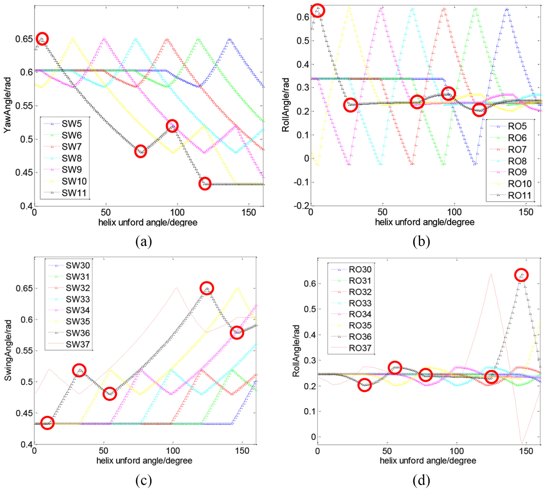
Variation curve of joint angle when the robot is crossing an obstacle: (a) angle variations of yaw joint of units 5–11, (b) angle variations of roll joint of units 5–11 (c) angle variations of yaw joint of units 30–37, and (d) angle variations of roll joint of units 30–37.
In Figure 16(a)–(d), the joint angular displacement curve is continuous without interruption, which shows that each joint angle of the robot did not change abruptly in the course of the movement. There is no joint whose speed changes abruptly during movement. In other words, no singular configuration occurs. Thus, the gait-generating method proposed herein is realizable.
However, we also see some angular displacement points on the robot’s articulation angle curve, which means that the velocity at these points is discontinuous, that is, at the point where the velocity is shown as a red circled point. That is, the speed changed abruptly at these points (shown as red circled point). These trends will be replicated by the method of transition from head to tail. These points would cause a kinematical impact and should be removed.
Smooth transition of trajectory joint points
The analysis specified in section “Simulation experiment of obstacle crossing process” indicates that the robot has a kinematical impact caused by the joint point with velocity discontinuity, the reason of which, through analysis, lies in the discontinuity of the first derivative of the trajectory near the intersection of curves on each stage, thus resulting in mutation of the fitted joint velocity. Consequently, the trajectory should be smoothed to achieve continuity of the first derivative.
In this study, B-spline curves are used for smoothing, as shown in Figure 17.

Diagram of discontinuous curve for smoothing.
The tangent vector of


Solving equation (39) can achieve a smooth transition between line 1 and bridge 1.
Simulation analysis after algorithm improvement
The effect of improvement on velocity discontinuity by B-spline curves smoothed in the process of robot obstacle crossing is verified. A simulated analysis is performed on this process, under the condition substantially identical with that under section “Simulation experiment of obstacle crossing process,” and the only difference between them is adding B-spline curves for smoothing. Suppose

The joint angles of joints 5–11 when the robot is moving along the smoothed trajectory to cross the obstacle are shown in Figure 18. Comparison with the unsmoothed angle trajectory, as specified in section “Simulation experiment of obstacle crossing process,” indicates that the tendencies of joint trajectory are similar to each other, but the smoothed trajectory has neither point of joint velocity discontinuity nor point of excessively high velocity. Therefore, the plan of smoothed trajectory is more suitable for generating gait of obstacle crossing.

Variation curve of joint angle when the robot is crossing an obstacle.
Conclusion
This study designs a P-R-joint scale-driven winding/climbing snake-like robot, which can cross variable-diameter cylindrical obstacles. The behavioral evolution of the position and posture of each joint in the process of crossing variable-diameter cylindrical obstacles is evaluated. A gait-generating method is proposed by following the principle of curve fitting. When the robot needs to cross a cylindrical obstacle, the transition curve is introduced to connect two equal pitch spiral curves; thus, the robot operates from a spiral winding way into another spiral winding way. The position and speed of each joint continuously change during the whole movement of the robot, and the robot body and the wound cylinder have no interference, which should be guaranteed. The main contributions of this study are as follows:
The kinematics of the snake-like robot is studied.
The robot attitude is considered in this study of the robot while crossing obstacle. Therefore, only the degree of freedom of rotation and the degree of freedom of deflection are considered in the kinematic analysis. The kinematic equation of the snake-like robot is obtained according to the established coordinate system to solve the kinematic problem, and the transformation matrix between the joints and the coordinate representation of the relative coordinate system is obtained.
A gait generation method based on polyline fitting is proposed.
Polyline is used to replace the robot unit. The polyline node is the connection point of the adjacent unit of the robot and the joint point. The trajectory curve is fitted with a polyline; thus, the joint position can be obtained. When the degree of freedom is not considered, the robot can be simplified as the P-R joint chain. The kinematic problem of the P-R joint chain is described by the exponential method. The relationship between joint angle and joint position can be obtained by kinematic inverse solution. Therefore, the joint angle can be obtained when the snake-like robot moves along a specific curve.
The snake-like robot winding and barrier climbing gait is studied.
For the variable-diameter obstacle, the trajectory curve of the snake-like robot is planned. The trajectory curve is a variable-diameter helix, and the snake-like robot in a quasi-static state is studied based on the multi-line fitting according to the planned trajectory curve. The validity of the method based on polyline fitting is verified. Finally, the entire obstacle crossing process of the snake-like robot is simulated. The robot has neither tangential displacement nor tangential friction on the stage of cylinder winding and neither point of joint velocity discontinuity nor point of excessively high velocity would be generated in the process of obstacle crossing once the trajectory is smoothed. Therefore, the locomotion-planning requirement on the crossing of a variable-diameter cylindrical obstacle of the robot can be met.
Footnotes
Handling Editor: Seung-Bok Choi
Author note
Zhiyong Yang, the corresponding author, works in Center for Robotics Research, School of Mechanical Engineering, Hubei University of Technology.
Declaration of conflicting interests
The author(s) declared no potential conflicts of interest with respect to the research, authorship, and/or publication of this article.
Funding
The author(s) disclosed receipt of the following financial support for the research, authorship, and/or publication of this article: This work was supported by the National Natural Science Foundation of China (Grant No. 51105281) and PhD start fund of Hubei University of Technology (BSQD2016001).