
Abstract
This paper presents a new lower limb rehabilitation robot (hereafter, referred to as LLR-Ro) to help patients with lower limb disorder recover their movement function. Based on the ergonomics and kinematics principle, the motion of a human lower limb is analysed, which provides a theoretical basis for the leg mechanism design of LLR-Ro. This paper also proposes a teaching training method for improving the training performance of LLR-Ro. When a physician trains the lower limb of a patient, the acceleration data of the patient's lower limb motion will be collected through a wireless data acquisition system. The data can reproduce the movement trajectory of the physician rehabilitation training and this can be used as the training trajectory of LLR-Ro. The experiment results of this study demonstrate that the teaching training method is feasible. The theory analysis and experimental research of LLR-Ro lay the foundations for the future clinical application of this method.
1. Introduction
Rehabilitation robotics is an application of robotic technology for people with limb disabilities [1, 2]. Elderly people are the most subject to cerebral vascular disease, hemiplegia and paraplegia. These diseases may cause limb motor dysfunction [3]. According to the statistics of the World Health Organization (WHO), by 2050, the world population of people over 60 will be double and the number of people disabled by disease will also increase [4]. Thus, there is an urgent increase in the demand for rehabilitation robots [5]. In recent years, research on rehabilitation robots has become an active topic [6, 7]. Several kinds of lower limb rehabilitation robots have been developed. These can be divided into trainers with single degree of freedom, wearable trainers, suspended gait trainers and sitting/lying gait trainers. As trainers with a single degree of freedom have a poor training effect and wearable trainers need the patient to be able to walk independently, this paper will only discuss suspended gait trainers and sitting/lying gait trainers.
The Lokomat [8–11], which was developed by Hocoma AG (Volketswil Switzerland), is the first driven gait orthosis. It can improve the walking movements of patients who are gait-impaired. Veneman et al. designed a gait rehabilitation device called LOPES [12, 13], which can automatically adapt to each patient's gait in order to help him/her stand up and walk. Other typical suspended gait trainers include Haptic Walker [14], LokoHelp [15, 16], Gangtrainer GT I [17, 18] made in Germany, ReoAmbulator made in USA and so on.
The Swortec company developed an advanced sitting gait trainer, MotionMaker [19]. This trainer is composed of two robotic orthoses comprising motors and sensors, and a control unit that manages the transcutaneous electrical muscle stimulation with real-time regulation. YILDIZ University of Science and Technology in Turkey made a sitting/lying gait trainer, Physiotherabot, which helps patients do passive training and active training [20]. Bouri et al. proposed a new rehabilitation robot [21]. This has position and force sensors at each motorized articulation, which allows all of the movements and corresponding generated forces to be controlled.
Although researchers have developed many lower limb rehabilitation robots, only a few of them are suitable for patients at any injury level. Suspended gait trainers are suitable for patients that have stand-up ability in their middle and late recovery and they do, indeed, have a good effect. However, they are not suitable for patients in their early stage of recovery. Despite ongoing improvements, existing sitting/lying gait trainers still require patients or physical therapists to adjust the length of the robot leg mechanism to fit the patient's leg. This paper proposes a new sitting/lying multi-joint lower-limb rehabilitation robot, LLR-Ro, which can overcome these problems.
Most people and institutes researching medical rehabilitation pay more attention to patient motor function. Few of them focus on physician rehabilitation methods. The teaching training method involves the rehabilitation robot getting the clinical training process data when the physician is treating the patient. It then uses a certain technology conversion to its control program to reproduce the treatment movements. It can combine the clinical experience of the rehabilitation physician with the rehabilitation robot, so as to provide a scientific and optimal rehabilitation plan and improve patient training efficiency. As a new rehabilitation method, it has rarely been studied. Morita et al. developed teaching/training function algorithms for personalized rehabilitation. The teaching/training function can record the patient's upper limb motion parameters while the physician is treating the patient. Then, based on the above parameters, the same treatment movement is realized by a robot [22]. However, this method obtains the motion parameters through the sensors on the robot, and the inertia of the robot mechanical arm influences the recording of the patient motion parameters.
In addition, the accelerometer can obtain reliable and accurate human motion information for analysis [23]. Therefore, this paper proposes a teaching training method of LLR-Ro using accelerometers. The basic principle is that accelerometers are fixed at specific positions of the patient's lower limb. The data acquisition system, which is based on accelerometers, obtains lower limb movement acceleration data during rehabilitation, when the physician is treating the patient. The data are then converted to LLR-Ro control information and the leg mechanism of LLR-Ro will repeat the treatment trajectory and speed to train the patient.
2. The Development of the LLR-Ro Mechanism and Wireless Data Acquisition System
2.1. Innovative mechanism design of the LLR-Ro
The main feature of LLR-Ro is the leg mechanism design. In order to realize a leg mechanism design that is optimally compliant with the principles of ergonomics and kinematics, allowing users with different heights to use LLR-Ro without manual intervention, the lower limb of an ordinary adult is analysed (shown in Figure 1).
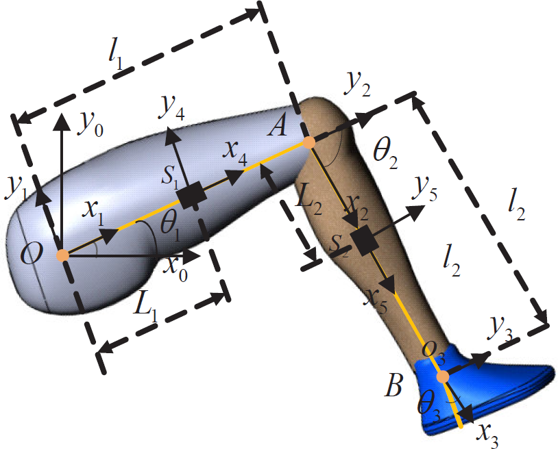
Lower limb analysis of an ordinary adult
Based on the analysis of the adult lower limb, it is clear that the lengths of different adults' thigh and calf are changeable. Thus, the design of the leg mechanism needs to satisfy the dimensional variation (shown in Table 1).
Length of each lower limb segment

The maximum range of motion of each joint training angle is obtained (shown in Table 2). This must meet the demand of the patient participating in daily activities and ensure the patient's safety at all times during training.
The range of motion of each joint

To replace rehabilitation doctors helping patients with dyskinesia of the legs and guiding their rehabilitation training correctly, LLR-Ro has important requirements for the sensing system. The sensing system contains sensors to measure joint rotations and estimate the torque and force produced by the patients. The torque sensors are installed on the axis of the joints. These can directly acquire the joint torque values. The length auto-adjustment devices of the leg mechanism used for thigh length adjustment and calf length adjustment are designed using a motor-driven pushrod and a slider. Its design principle, as shown in Figure 2, is that one end of the pushrod is connected with the rack and the other end is connected with the relative moving part. Meanwhile, the rail is installed on the rack and a slider is installed on the moving part, so when the length of the pushrod is changed, the moving part is in motion with respect to the rack.
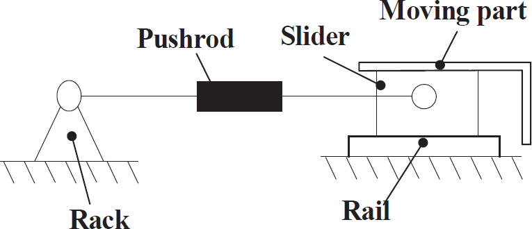
The principle of length auto-adjustment
The detailed design of the LLR-Ro leg mechanism is shown in Figure 3.
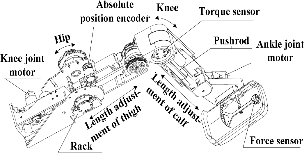
The detailed design of LLR-Ro leg mechanism
The prototype of LLR-Ro is devised based on the design of a leg mechanism. It can realize passive training, active training and teaching training. On account of its working circumstance and specific users, research on LLR-Ro is also focused on its comfort and aesthetics, as shown in Figure 4.

The prototype of LLR-Ro
2.2. The design of the wireless data acquisition system
In this paper, the human lower limb acceleration data acquisition system is designed, including PC, data acquisition master system (MAS) and data acquisition slaver system (SLA). The MAS communicates with each SLA via the wireless data transmission module by using the communication system configuration mode of star point to multipoint. The system is shown in Figure 5.

The design of the wireless data acquisition system. a) The block diagram of the wireless data acquisition system. b) The hardware photo of the wireless data acquisition system.
2.2.1. Hardware design of the system
The MAS includes a control unit, the NRF24L01 wireless data transmission module, a serial communication module and a power module. Its main function is to receive and analyse the serial control instruction from the PC, receive acceleration data from each SLA and send them to the PC. The SLA includes a control unit, the NRF24L01 wireless data transmission module, the ADXL345 accelerometer module and a power module. Its main function is to collect the current acceleration value via the ADXL345 accelerometer module and send this to the MAS through the NRF24L01 wireless data transmission module.
2.2.2. PC software design of the system
The PC obtains the data from MAS and processes them by converting the acceleration value into a corresponding angle value. It then obtains and displays the present end point position of the lower limb through the formula of forward kinematics. Finally, a smooth teaching training track is obtained by means of dealing with the original end point position of the patient's lower limb. The software flow chart is shown in Figure 6.
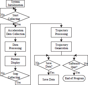
The software flow chart
The PC software programming is based on LabVIEW software, including the time-sharing acceleration data collection, data processing, trajectory generation and other additional functions. The PC software user interface includes preferences, control buttons, angle display, gesture display and end point trajectory display, as shown in Figure 7.

The PC software user interface
The PC software proceeds as follows:
Firstly, the parameters that include the serial port communication configuration parameters, human lower limb parameters and so on are inputted into the input box. Then, by clicking the control buttons, the PC starts to obtain the acceleration data and the angle value of the hip and knee, and the waveform plots from the data are displayed in real time. Meanwhile, the gesture of the human lower limb is shown in the gesture display window.
3. Accelerometer-based Motion Tracking Algorithm of the LLR-Ro
In this paper, the trajectory of the human lower limb is obtained by using accelerometers. Thus, the relation of the human lower limb motion trajectory and acceleration need to be set up. The trajectory is the position sequence of the lower limb end points, which can be determined by the length parameters of the leg segments and the angle parameters of the joints. So, the basic research content of the LLR-Ro teaching training method is to determine the relationship between the lower limb joint angles and leg segment accelerations, as well as the relationship between the joint angles and lower limb end positions.
3.1. Relationship between the joint angles and end point position
The position of the lower limb end point is mainly determined by the rotation of the hip and knee, so the lower limb model is simplified as a two-link mechanism, as shown in Figure 1, where OA is the thigh (link1), AB is the calf (link2), l1, l2 are the lengths of the thigh and calf respectively, O, A, B are the hip, knee and ankle joint,
Thus, the position coordinates of point B relative to the base coordinate system are:

3.2. Relationship between the link accelerations and joint angles
The accelerometer is a digital triaxial accelerometer ADXL345, produced by the ADI Company and developed with MEMS (Micro-electromechanical Systems) technology. The usage of accelerometers is shown in Figure 8. The plane of the ADXL345 chip is arranged vertically and the x-axis is consistent with the axial direction of the thigh and calf.

The use of accelerometers
The relation between the velocity and acceleration of each link is then derived. To do this, the Recursive Newton-Euler method is used. The characteristic of this method is to describe the movement of the link in its own coordinates. The movement of the link is generally described by linear velocity, linear acceleration, angular velocity and angular acceleration of the link coordinate [24].
The transformation equation for angular velocity and linear velocity can be expressed as:

The transformation equation for angular acceleration and linear acceleration can be expressed as:

where vi and ωi are the linear and angular velocity of the link in coordinate {i} relative to the base coordinate system,
3.2.1. Single-joint model
In order to obtain information on a single joint of the patient motion data, only the relationship between the hip joint angle and the acceleration of the thigh is studied. This is because the relationship between the knee joint angle and the acceleration of the calf is similar. Since the thigh movement can be seen as a rigid body rotating around the hip joint at the plane x0y0, the single-joint model is shown in Figure 9. S1-x4y4 is fixed on the position of the accelerometer centre, S1, L1 is the length between O and the installation location of the thigh accelerometer S1.

The single-joint model
Each link coordinate transformation can be expressed as follows:


As the coordinate system {0} is stationary, the following equation can be obtained:

According to equation (1) and (3), linear and angular velocities of the link coordinate systems {1}, as well as linear and angular accelerations of the link coordinate systems {1}, can be obtained:

As
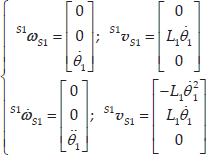
The rotation transformation of the link in coordinate system {S1} with respect to the base coordinate system {0} can be obtained:

So, the angular

The linear acceleration

In the formula, ax is the measured value of the accelerometer along the x-axis in {S1}; ay is measured value of accelerometer along the y-axis in {S1}; g is the gravitational constant.
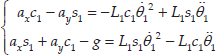
Through simultaneous equations (10) and (11), the second order differential equation group about θ1 can be obtained:
3.2.1.1. The calculation method to get the initial hip angle
In order to get initial acceleration of the accelerometer, this paper describes the relationship between the hip joint angle and accelerometer value in all four quadrants of the coordinate system, as shown in Figure 10.

Relationship between the hip joint angle and accelerometer value
When the patient's thigh is in a stationary or almost stationary state, the right parts of equations (12) equal zero, so we can get:

In the above formula (13), θ1 cannot be equal to
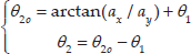
For practical purposes, there are different formulas to get θ1 for ax and ay in different quadrants:
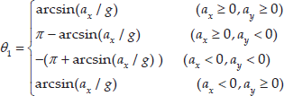
In the formulas (14), we can get θ1 by using just the x-axis value of the thigh accelerometer. However, when θ1 is near

The relationship between the output accelerometer and θ1
The new formulas to replace the formulas (14) are obtained:

3.2.1.2. The calculation method to get the hip joint angle in a dynamic state
When the thigh is in motion, the backward difference method is adopted to calculate the hip joint angle.

In the formula,
Through the simultaneous equations (12) and (16), the solving method of the joint angle calculation in a dynamic state can be obtained:

3.2.2. Double-joint model
According to equation (2), the linear and angular velocities of the link are obtained in the coordinate systems {2} and {S2}:

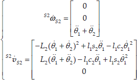
According to equation (3), the linear and angular accelerations of the link are obtained in the coordinate systems {2} and {S2}:


The rotation transformation of the link in coordinate system {S2} with respect to the base in coordinate system {0} can be expressed as follows:

So, the angular

The linear acceleration of the calf relative to the base coordinate system can be obtained by the accelerometer fixed on the calf:

From the simultaneous equations (23) and (24), the second order differential equation group concerning θ2 is obtained, as follows:

With the well-known relations:

3.2.2.1. Double joint angle calculation in a static state
When the patient's leg is in a stationary or almost stationary state and the right parts of equations (25) equal zero, we can get:
3.2.2.2. Double joint angle calculation in a dynamic state
Using the same backward difference method to calculate the double-joint angles, we can get:

In the formula,
Based on the above analysis, it can be concluded that the leg motion speed must be slow at the beginning, when using the accelerometers to get the initial leg position data. After that, the dynamic angle calculation method is used to obtain the leg position during treatment. Thus, the human lower limb trajectory can be reproduced after determining the patient's hip joint angle θ1 and knee joint angle θ2
4. The Experiment and Analysis of the Results
The research team completed the experiment with the help of three participants. Table 3 shows their height and lengths of their body segments. SLA-1 and SLA-2 installation locations are 200mm and 210mm, respectively.
The lower limb lengths of participants

The procedures of the three participants are the same. During the experiment, the participant's right leg completed the movement with the help of the other people. The wireless data acquisition system collected the participant's acceleration data. The acceleration was converted into angle data, which were used to generate the trajectory and control the robot to train the participant. The robot motion data were also collected during the training process and was then used to generate the robot trajectory. Finally, comparing the trajectory of the human with the trajectory of LLR-Ro, the feasibility of the LLR-Ro teaching training method using the wireless data acquisition system was analysed. The robot teaching training experiment flow chart is shown in Figure 12.

The robot teaching training method experiment flow chart
Following the steps above, the teaching training experiments of LLR-Ro were completed and the joint motion curves of the participants were obtained, as shown in Figures 13 (a) and 13 (b). The joint motion curves of LLR-Ro that were used for the participants' rehabilitation training were obtained with smoothing processing, as shown in Figures 13 (c) and 13 (d). It can be found that the joint training curves of LLR-Ro are not only consistent with the joint motion curves of the participant but also, they have high smoothness.

The participants' joint motion curves and LLR-Ro joint training curves. a) The participants' hip motion curves. b) The participants' knee motion curves. c) LLR-Ro hip training curves. d) LLR-Ro knee training curves.
The trajectory comparison between the participants and LLR-Ro is shown in Figure 14.

The trajectories comparison between the participants' and LLR-Ro's data. a) The trajectories were generated by the participants. b) The trajectories were generated by LLR-Ro.
From Figure 14 a), we know that the trajectories generated by the participants are quivering, which is not suitable to train the user in the long-term. In Figure 14 b), the trajectories generated by LLR-Ro were smooth in comparison to the former. In addition, from Figure 14, the overall motion trend is consistent and the overall coincidence degree is good with the error in the allowable range.
5. Conclusions
This paper describes a sitting/lying lower limb rehabilitation robot (LLR-Ro) that is suitable for patient rehabilitation training at any injury level. The length of the LLR-Ro leg mechanism can be adjusted to adapt to the patient by electric adjustment. A wireless data acquisition system that is based on an accelerometer is developed to obtain the patient's lower limb motion data when the physician is training him/her by hand. Finally, a teaching training method is proposed and the experiment demonstrates that LLR-Ro can repeat the physician treating movement by using this method. The research on LLR-Ro not only lays the technological and theoretical foundations for further clinical trials, but also provides a technical reference for similar projects in recovering patients with lower limb motor dysfunction.
Footnotes
6. Acknowledgements
This work is supported by Special Research Found for the Doctoral Program of Higher Education (no. 20131333110006), the Natural Science Foundation of Hebei Province of China (no. E2015203405) and the High Level Talent Project in Hebei Province.