
Abstract
This article presents the mechanical design, dimensional optimization, finite element analysis, and experimentation of a 2-degree-of-freedom flexure-based micro-motion stage. The stage is composed of four parallel limbs with symmetrical configuration, and each limb is composed of two serially connected prismatic joints. The divided parts of flexure hinge thickness constituting the two prismatic joints are selected as two. Based on analytical models established in stiffness and dynamic analysis, the dimensional optimization is carried out to maximize the first resonance frequency. Finite element analysis is then adapted to verify the stiffness, workspace, and dynamic behavior. Finally, a prototype of the stage is manufactured and an experimental platform is set up. The experimental results show that the stage has a workspace range of 19.53 µm × 19.07 µm with a frequency of 1987 Hz, and the cross-coupling ratio between two axes is less than 1%. For high-frequency cooperative tracking experiments, a proportional–integral controller is implemented to compensate for the tracking errors. Finally, good tracking performance at high frequency is obtained, which validates the effectiveness of the micro-motion stage.
Introduction
Flexure-based micro-motion stages, which have advantages of no friction, no hysteresis, no backlash, ease of fabrication, and compactness, can provide smooth motions and are capable of obtaining motions with nanometer-level resolution.1–3 Considering these advantages, flexure-based micro-motion stages have been widely used in many industrial applications, such as scanning probe microscopy, biological science, micro-grippers, and semiconductor production.4–7 The piezoelectric actuators (PZTs) can provide fast and ultra-precision motions, and they are widely used to drive micro-motion stages.8,9
Recently, high-speed micro-motion stages with high-frequency cooperative tracking are increasingly required in many fields, such as biological molecules and automated tests of accelerometer transverse sensitivity.10–12 The international standard ISO 16063-31 provides several methods for testing of accelerometer transverse vibration sensitivity. 13 Obviously, flexure-based micro-motion stages with high-frequency cooperative tracking performance can be used to test the accelerometer transverse sensitivity.
To provide high-frequency cooperative tracking performance, the stage should be rigid and compact. The parallel structure which possesses high rigidity, high load carrying capacity, and high accuracy could be selected. Numerous parallel micro-motion stages have been developed.14–19 A parallel high-bandwidth nano-positioning stage was designed. 20 A novel center-thickened beam was used to achieve high first frequency about 8269 Hz. The input stiffness was 31.4 N/µm, while the stiffness of PZTs was chosen as 140 N/µm to meet the requirement. Polit 21 designed a high-bandwidth XY nano-positioning stage. This stage had two axes, and each axis was composed of a doubly clamped beam and a parallelogram hybrid flexure. The resonant frequencies of the two vibrational modes were over 8 kHz, and the workspace was 15 µm along each axis. To obtain the resonant frequency, the stiffness of the stage should be selected as larger as 41 N/µm, while the stiffness of PZTs should be larger. Li 22 introduced a compliant parallel micro-motion stage. A symmetric 4-PP structure was adopted to obtain good stiffness and decoupled property. The mechanism had a workspace of 19.2 µm × 8 µm with a first frequency of 720.52 Hz. The stiffness was 4.85 N/µm and the cross-coupling ratio was less than 5%. Qin 23 derived a decoupled 2 degree-of-freedom (DOF) monolithic mechanism. The decoupled property can be obtained by the statically indeterminate leaf parallelograms, and the PZTs’ displacements were amplified with a statically indeterminate lever mechanism. The developed mechanism had a workspace of 82 and 82 µm with a first frequency of 423 Hz. The stiffness was 0.57 N/µm, and the cross-coupling ratio was measured to be less than 1%. Lai et al. 24 proposed a decoupled 2-DOF translational parallel micro-positioning stage. The developed stage had a workspace of 40 and 40 µm with a first frequency of 340 Hz, and the stiffness was 1.62 N/µm.
Various parallel micro-motion stages have been widely developed. Nevertheless, the high-frequency cooperative tracking is limited by the resonance frequency, the stiffness, the workspace, and the decoupled property. Moreover, the stages with high resonance frequency possess large stiffness, and the stiffness would be in contradiction with the workspace and motion accuracy. In addition, the stages possessing large stiffness need to be actuated by large-stiffness PZTs. Therefore, it is necessary to develop a parallel micro-motion stage with high resonance frequency, relatively small stiffness, good decoupled property, and large workspace. This article addresses the design and analysis of a 2-DOF flexure-based micro-motion stage for high-frequency cooperative motion. In the mechanical design, two prismatic joints are employed to obtain high resonance frequency and large workspace, and they are designed according to the divided parts n of the flexure hinge thickness. In addition, the distance between two neighboring hinges of the prismatic joints is considered in the dimensional optimization. The connecting structure for the PZTs is particularly designed. To verify the validity and effectiveness of design and analysis of the stage, finite element analysis (FEA) and experiments have been done. Finally, the circular trajectory tests with high input frequencies are completed.
The remaining sections of this article are organized as follows. Section “Mechanical design, stiffness modeling, and dynamic analysis” describes the mechanical design, stiffness modeling, and dynamic analysis of the stage. Mechanical structure with symmetrical configuration and the detailed design of prismatic joints are analyzed in the mechanical design. In section “Dimensional optimization,” the dimensions of the stage are optimized to maximum the first resonance frequency, get good decoupled property, and obtain enough workspace. In section “FEA and results,” FEA is adopted to validate the design and performance of the stage. In section “Experimental setup and performance tests,” experiments have been done, including the workspace and cross-coupling displacements, stepwise responses with 1 µm and 10 nm steps, frequency responses of the system, and tracking performance tests for circle trajectories with various input frequencies. Finally, conclusions are drawn in section “Conclusion.”
Mechanical design, stiffness modeling, and dynamic analysis
Mechanical design
For a 2-DOF flexure-based micro-motion stage, it is usually composed of two or four parallel limbs, as illustrated in Figure 1. The output platform can achieve motion along any direction on the XY plane injunction with the consideration of the independent translational motion along x-axis and y-axis. Several typical 2-DOF micro-motion stages are depicted in the literatures.6,8,23,24 Without loss of generality, the micro-motion stages are composed of four parallel limbs, and each limb is composed of two serially connected prismatic joints. The symmetrical configuration of the prismatic joints could keep the orientation of the platforms invariant when the micro-motion stage is actuated along one axis. Meanwhile, undesired cross-coupling error along the other axis, which makes it difficult for the kinematic analysis and control of the micro-motion stage, could be avoided. To derive good decoupled property, the stage could be designed with symmetrical configuration, as shown in Figure 1(b).

2-DOF micro-motion stages: (a) with two parallel limbs and (b) with four parallel limbs.
As shown in Figure 1(b), each limb is composed of two prismatic joints P1 and P2. The prismatic joint P1 is composed of four joints P1-1, P1-2, P1-3, and P1-4, while the prismatic joint P2 consists of four joints P2-1, P2-2, P2-3, and P2-4. In fact, the essential point is to design ideal prismatic joints P1 and P2. The prismatic joint P2 is connected to the fixed base directly, and it has the input platform which can provide the forces actuated by the PZTs to the micro-motion stage and connect to the prismatic joint P1. The prismatic joint P1 connected to the output platform could transmit the deformations of the flexure hinges to the output platform.
For a notch flexure hinge, there are strong couplings between the translational and rotational motions. Furthermore, the rotation center of a flexure hinge drifts whenever the hinge works, resulting in motion errors. In practice, flexure hinges could be combined to form certain flexure-based joints to derive the decoupled property. 25 The constant rectangular cross-sectional flexure hinges divided into two parts are chosen as the basic elements, as depicted in Figure 2(a). In order to obtain decoupled property, the basic prismatic joint could be symmetrical, as illustrated in Figure 2(b).

Basic prismatic joints: (a) the flexure hinge with the variable divided parts 2 and (b) the symmetrical prismatic joint with the variable divided parts 2.
According to the analysis above, the symmetrical prismatic joint as shown in Figure 2(b) could be chosen. The flexure hinge thickness t can be divided into n parts. As illustrated in Figure 2(b), the divided parts are 2, and geometrical dimensions include the hinge length L, the hinge thickness t, and the distance between two neighboring hinges d. When the divided part is 1, the in-plane stiffness matrix of the symmetrical prismatic joint can be expressed as
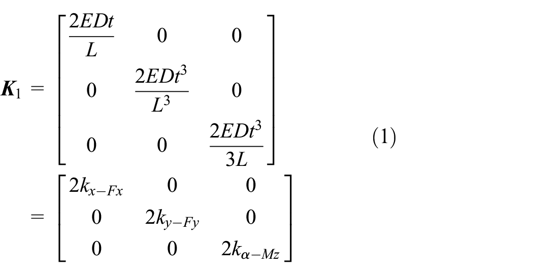
where D is the total depth of the flexure hinge, E is the Young’s modulus, and
When the hinge thickness is divided into n parts, the symmetrical prismatic joint is composed of n flexure hinges, and the thickness of each flexure hinge is t/n. The stiffness of each flexure hinge can be expressed as equation (1). The stiffness located at point O (the center of the symmetrical joint) is the accumulation of the stiffness of each flexure hinge, and it can be expressed as

where Ki is the stiffness of the ith flexure hinge with respect to the point O.
From the equations above, it can be seen that the axial stiffness Kx-Fx is constant with the variable divided parts n. In addition, the stiffness items Ky-Fy and Kα-Mz could be associated with the variable divided parts n, and they all decrease with increasing n. The prismatic joints P2-1, P2-3, P1-2, and P1-4 have the same stiffness requirements. To achieve motion along the y-axis, the stiffness items Ky-Fy should be small, while the stiffness items Kx-Fx and Kα-Mz should be large. For the prismatic joints P1-1 and P1-3, the stiffness items Ky-Fy should be large, while the stiffness items Kx-Fx and Kα-Mz should be small to transmit the deformations of the flexure hinges to the output platform. Similarly, the prismatic joints P2-2, P2-4, P1-1, and P1-3 can be analyzed to achieve motion along the x-axis in the same way. Meanwhile, the stiffness could be decreased with increasing n. Therefore, considering the manufacturing and dimensions, the divided parts of the prismatic joints P1 and P2 could be selected as 2 illustrated in Figure 2. According to the analysis above, the structure of the micro-motion stage can be illustrated as in Figure 3.

Structure of the micro-motion stage.
In order to achieve relatively high-frequency cooperative tracking performance, the stage is designed to obtain high resonance frequency (about 2000 Hz), get good decoupled property (no more than 1.5%), and possess large workspace (no less than 18 µm × 18 µm). The mechanical structures have been analyzed above, and then the PZTs with a relatively high stiffness should be selected. The PZTs could be chosen according to the stiffness, the maximum nominal displacement, and the electrical capacitance. The stiffness of the PZTs should be larger than that of the stage. To obtain the maximum displacement, the maximum nominal displacement should be large. To work under high frequency, the electrical capacitance should be small. The PZTs can provide fast and ultra-precision motions, and two PZTs are selected to drive the micro-motion stage. The selected PZTs can work under a voltage ranging from 0 to 120 V. The maximum displacement of the selected PZTs under 150 V is 50 µm, and the maximum nominal displacement under 120 V is 32 µm. The stiffness is 25 N/µm, the electrical capacitance is 3.6 µF, and the length is 46 mm. The piezoelectric stack actuators are composed of several piezoelectric layers glued together, which are easily damaged by pulling forces and tangential forces. Therefore, the PZTs must be preloaded. The material for the mechanism is chosen as aluminum 7075 with a density of 2810 kg/m3, a Young’ modulus of 71 GPa, and a yield strength of 500 MPa.
Stiffness modeling
The stiffness is an essential property for the micro-motion stage, and it is closely related to the first resonance frequency, the maximum workspace, the motion accuracy, and so on. Therefore, the stiffness model should be obtained. Commonly, a flexure-based mechanism is composed of several flexure hinges connected in a serial or parallel structure. In order to obtain the stiffness/compliance, the local compliances have to be transformed to a global frame chosen to describe the mechanism. Then, compliances connected in serial and stiffness connected in parallel can be, respectively, added together to obtain the total stiffness/compliance. The stiffness model of the micro-motion stage can be graphically depicted in Figure 4.

Stiffness model of the micro-motion stage.
The input stiffness Kinput is defined as the stiffness of input end O1 (where the input force is applied) with respect to the ground, which should not exceed the output stiffness of the PZTs. The prismatic joints P2-1, P1-1, and Pm are connected at the center of the output platform, and the Pm is composed of the red parts of the stiffness model illustrated in Figure 4. The stiffnesses of prismatic joints P2-1 and P1-1 are K2-1 and K1-1, while the stiffness of the prismatic joint Pm is composed of K2-2, K2-3, K2-4, K1-2, K1-3, and K1-4. The input stiffness model also can be simplified as illustrated in Figure 5.

Simplified stiffness model of the stage.
According to the simplified stiffness model depicted in Figure 5, the stiffness of the red part and the input stiffness of the micro-motion stage can be expressed as


where
Dynamic analysis
According to mechanical design and stiffness modeling, the dynamic model of the stage could be obtained. There are fundamentally two methods for deriving dynamic equations of motion: vector methods and energy methods. Lagrange’s equation, which depends on energy balance, is employed for the dynamics modeling of the micro-motion stage because it is easier to get the energy equations of the flexure-based mechanism than vector equations. The displacements of the platform in x-axis and y-axis are chosen as the generalized coordinates of the stage, that is, q = [Δx, Δy]T. The kinetic energy of the micro-motion stage is composed of the P1, P2, and the output platform, expressed as

where TP1, TP2, and Tplatform are the kinetic energy of the prismatic joints P1, P2, and the output platform; Mex and Mey are the equivalent mass of the micro-motion stage in the x-axis and y-axis, respectively.
The total potential energy of the micro-motion stage is

where Vx and Vy are the potential energy of the micro-motion stage in x-axis and y-axis, respectively, while Kx and Ky are the input stiffness of the micro-motion stage in x-axis and y-axis respectively.
Using the Lagrange’s equation for the undamped free vibration of the micro-motion stage

The dynamics equation of the micro-motion stage can be derived as

where
Solving the characteristic equation, and then the natural frequencies fi of the whole system can be derived

Dimensional optimization
The micro-motion stage is composed of flexure hinges, which are easily influenced by their geometrical dimensions. The dimensions of the micro-motion stage are critical to the static and dynamic performances’ injunction with consideration of the analysis above. Hence, it is necessary to optimize the dimensions of the stage to obtain an ideal structure with optimal dimensions. The objective of the optimization is to maximize the first resonance frequency to obtain cooperative motion at relatively high frequency. The factors constraining the dimensions are composed of material properties, the performances of PZTs, the stiffness, the workspace, and so on. Meanwhile, the dimensions are optimized to obtain the workspace of the stage which is above 18 µm. To guarantee the stiffness of the stage in z-axis, the thickness of the stage is chosen as 10 mm. Meanwhile, the length and width of the output platform could be selected as 20 mm × 20 mm to install sensors and accessories. Considering the size of the PZTs, the input platform is chosen as 20 mm × 20 mm to connect to the mechanism and PZTs.
The variables to be optimized are the dimensional parameters of L1, L2, t1, t2, d1, and d2, as illustrated in Figure 3, while L1 and L2 are the hinge length of the prismatic joints P1 and P2, t1 and t2 are the hinge thickness of the prismatic joints P1 and P2, and d1 and d2 are the distance between two neighboring hinges of the prismatic joints P1 and P2. To meet the requirements of the stiffness, workspace, and resonance frequency, the proposed dimensions are relatively large, and thus, the parameter ranges can be determined. In addition, the dimensions of the output platform and input platform should also be considered. The constraints of the optimization are described as follows:
Objective: maximize the first resonance frequency.
Performances to be constrained:
Input stiffness: Kinput ≤ 8.5 N/µm
Workspace of the stage: ΔS ≥ 18 µm
Parameters to be optimized:
24 mm ≤ L1 ≤ 30 mm, 24 mm ≤ L2 ≤ 30 mm
5 mm ≤ t1≤8 mm, 6 mm ≤ t2 ≤ 8 mm
11.5 mm ≤ d1 ≤ 14 mm, 11 mm ≤ d2 ≤ 14 mm
The maximum displacement of the stage is
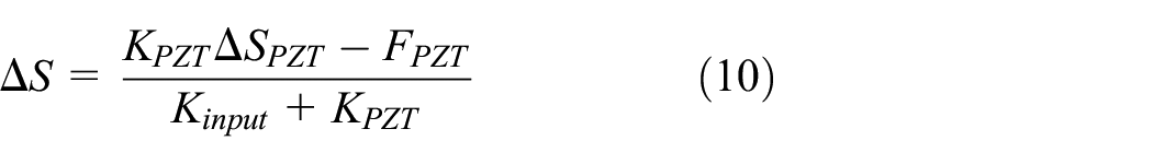
where ΔSPZT is the maximum nominal displacement of the PZT, FPZT is the preload applied on the PZT chosen as 200 N (recommended by the manufacturer), and KPZT and Kinput are the translational stiffness of PZT and the micro-motion stage, respectively.
The optimization process is carried out in MATLAB, and the optimal results are as follows: L1 = 25 mm, L2 = 28 mm, t1 = 5 mm, t2 = 6 mm, d1 = 11.5 mm, and d2 = 11 mm. Based on the optimized dimensions, the performances of the micro-motion stage can be obtained. The stage has a first resonance frequency of 2123.5 Hz, input stiffness of 8.27 N/µm, and a workspace of 18.03 µm × 18.03 µm.
FEA and results
The results calculated by FEA can be regarded as relatively accurate. FEA is performed to verify the design objectives of the 2-DOF micro-motion stage. In this work, FEA is performed using ANSYS Workbench software. The stiffness, workspace, stress distribution, as well as its dynamic behavior are studied using static analysis, respectively.
The forces can be applied at the input platform end O1 as illustrated in Figure 4, and the deformations can be obtained by FEA directly. The input stiffnesses along x-axis and y-axis are the same, and the value is 7.82 N/µm. Clearly, the FEA result is almost similar to the theoretical value, which proves the accuracy of the input stiffness modeling. According to equation (10), the workspace of the stage can be calculated easily. The workspaces along x-axis and y-axis are the same, and the value is 18.28 µm. Obviously, the FEA value is similar to the theoretical workspace, which proves the accuracy of the theoretical value. To test the stress distribution, the maximum input force (F = 600 N) is applied to the micro-motion stage along the x-axis and y-axis, respectively. The results actuated by the force along the x-axis and y-axis are almost same. The von Mises stress distribution actuated by the force along the y-axis can be depicted as in Figure 6. It can be seen that the maximum stress is 43 MPa occurring near the connection parts between the constant rectangular cross-sectional flexure hinge and the platforms. It is much lower than the allowable stress (250 MPa) of the material, which indicates that the micro-motion stage can achieve a larger workspace without material failure.

Stress distribution under the maximum input force.
The vibrational modes and the corresponding natural frequencies of the micro-motion stage are also analyzed by FEA. Figure 7 shows the three most dominant mode shapes for the micro-motion stage. The first two modes are related to the displacement of the output platform that is actuated by the PZTs. Clearly, the first two modes are the output platform’s in-plane translations, and the frequencies are slightly different due to the manufacturing errors of the stage. The third mode, the output platform’s translations along z-axis, should be strictly attenuated as it brings in parasitic rotations. The dominant model has a resonant frequency of 2016 Hz, which verifies the theoretical analysis and provides relatively high potential for fast operation and high throughput.
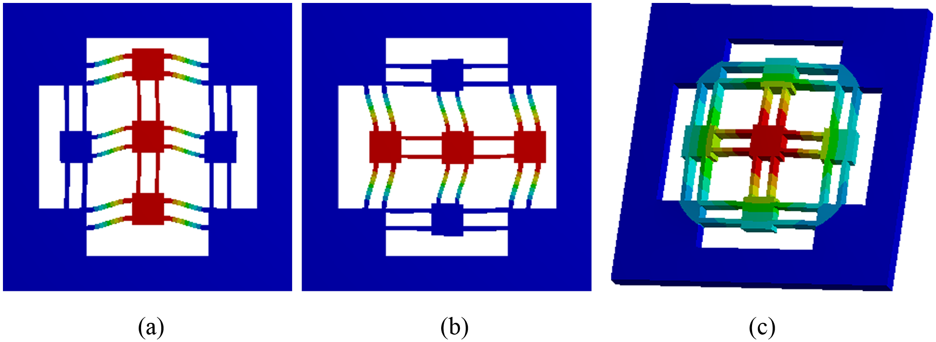
Vibration modes and their corresponding frequencies: (a) first frequency at 2016.2 Hz, (b) second frequency at 2016.2 Hz, and (c) third frequency at 2325.1 Hz.
Experimental setup and performance tests
Experimental setup
An overview of the experimental testing apparatus is depicted in Figure 8. The 2-DOF micro-motion stage is fabricated by the milling process using aluminum 7075, and it possesses dimensions of 190 mm × 190 mm ×10 mm. The geometrical dimensions of this stage are relatively large. There is enough space to machine the stage by milling process. In addition, the time for machining is short, and the cost is low. Moreover, the machining accuracy is high, and it can meet the design requirements. The two preloaded PZTs (PSt 150/7/40 VS12 from XMT Harbin, Inc.) are mounted to actuate the micro-motion stage. The PZTs are driven by a two-axis piezo amplifier and driver (XE500/E05 from XMT Harbin, Inc.) with a voltage ranging from 0 to 120 V. The displacements of the output platform are measured by two catalog-length guages (MT 1281 from Heidenhain, Inc.). To reduce vibrations, the air spring optical platform (1209M-100T) made in South Korea is employed. A dSPACE-DS1107 board equipped with the 16-bit analog-to-digital converters and 16-bit digital-to-analog converters is used to control the whole system. To close the position loop, a proportional–integral (PI) controller could be implemented on the controller. The dSPACE board can be used for receiving displacement feedback from the catalog-length gauges, calculating the control and send it to the amplifier. The 16-bit analog-to-digital converters are used to translate the analog voltage positional signal to digital signals used by the PI controller. The amplifier can be used to receive command signals from the PI controller and provide amplified voltage to drive the PZTs. As shown in Figure 8(b), the connecting structure for the PZTs is special. The connecting block is used to connect the PZTs and the flexure-based mechanism, and the end plate is used to fix the PZTs along axial direction. For this micro-motion stage, there is clearance between the end plate and the flexure-based mechanism to apply the preload easily. Each actuator is preloaded through the screw mounted at the tip of the end plate.

Experiment setup: (a) experiment testing system and (b) micro-motion stage.
Static performance tests
The static performance of the 2-DOF micro-motion stage is experimentally tested. The relationship between the static displacement and the actuation voltage is demonstrated in Figure 9. The actuation voltage ranging from 0 to 120 V is applied to one axis, and the displacements of both axes are obtained. Figure 9(a) shows that the working ranges of x-axis and y-axis are 19.53 and 19.07 µm, respectively, which are a bit larger than the theoretical and FEA results. The reason for this phenomenon is that the preload is considered to be 200 N in the theoretical analysis and FEA, while it may be less in the experiment as it is difficult to measure. The relationship between the displacement and the actuation voltage is nonlinear, which is due to the hysteresis of the PZTs. It can be seen from Figure 9 that a parasitic translation occurs in the y-axis (x-axis), when the micro-motion stage moves along the x-axis (y-axis). Meanwhile, the test of cross-coupling between two axes is also performed and the results are depicted in Figure 9(b). The maximum cross-couplings in the x-axis and y-axis are 0.118 and 0.194 µm, accounting for 0.62% and 0.99% of the maximum displacements, respectively. The reasons for the cross-coupling are mainly the manufacturing errors of the micro-motion stages, assembly errors of the PZTs and the catalog-length gauges, and different performances of the apparatus. The experiments results demonstrate that the micro-motion stage possesses nearly decoupled performance.

Experimental results of working range and cross-coupling displacements: (a) working range and (b) cross-coupling displacements.
Open-loop stepwise responses of the stage are illustrated in Figure 10(a), while closed-loop stepwise responses of the stage are obtained by the PI controller and the step size is 1 µm, as shown in Figure 10(b). As shown in Figure 10(a), the rising steps are larger than 1 µm, while the falling steps are not equal to 1 µm. The reason for this phenomenon is that the PZTs possess the nonlinear hysteresis characteristics. Obviously, PI controller can provide a repeatable and linear motion, and a resolution of 3 nm with 10 nm steps is obtained in the x-axis and y-axis as demonstrated in Figure 10(c).

Stepwise responses of the micro-motion stage: (a) open-loop step response with 1 µm steps, (b) closed-loop step response with 1 µm steps, and (c) step response with 10 nm steps.
First resonance frequency tests
In order to verify the first resonance frequency derived from finite element method (FEM) and theoretical model, a model hammer (Coinv MSC-3) is utilized to provide impulse force excitation. The first resonance frequency is tested by an accelerometer (PCB 356A16) mounted on the output platform. The data acquisition and analysis are performed using a modal analyzer (Coinv INV 3020D). Figure 11 illustrates the experimental results when only the x-axis is actuated. Similar results in the y-axis can be derived, but not illustrated herein. It can be found that the peak corresponds to the first mode. The experimental value is 1987 Hz. The results derived from FEM and theoretical model are 2016 and 2123.5 Hz, accounting for 1.4% and 6.8% error with the experimental value, respectively.

Experimental results of the first resonance frequency.
Tracking performance tests
Figure 12 illustrates the frequency responses of the system. A sinusoidal signal with amplitude of 0.5 µm along with varying frequencies (1–1400 Hz) is applied. The closed-loop frequency responses in the x-axis and y-axis are then derived. Within the ordinary −3 dB bandwidth, the bandwidths of 300 and 400 Hz are achieved for the x-axis and y-axis. The system has an almost flat magnitude response up to 130 and 150 Hz in the x-axis and y-axis, respectively, which provide a good potential for closed-loop control. According to the frequency response, the system can be relatively stable under the flat magnitude response. Therefore, the cooperative tracking performance tests are carried out below 100 Hz.
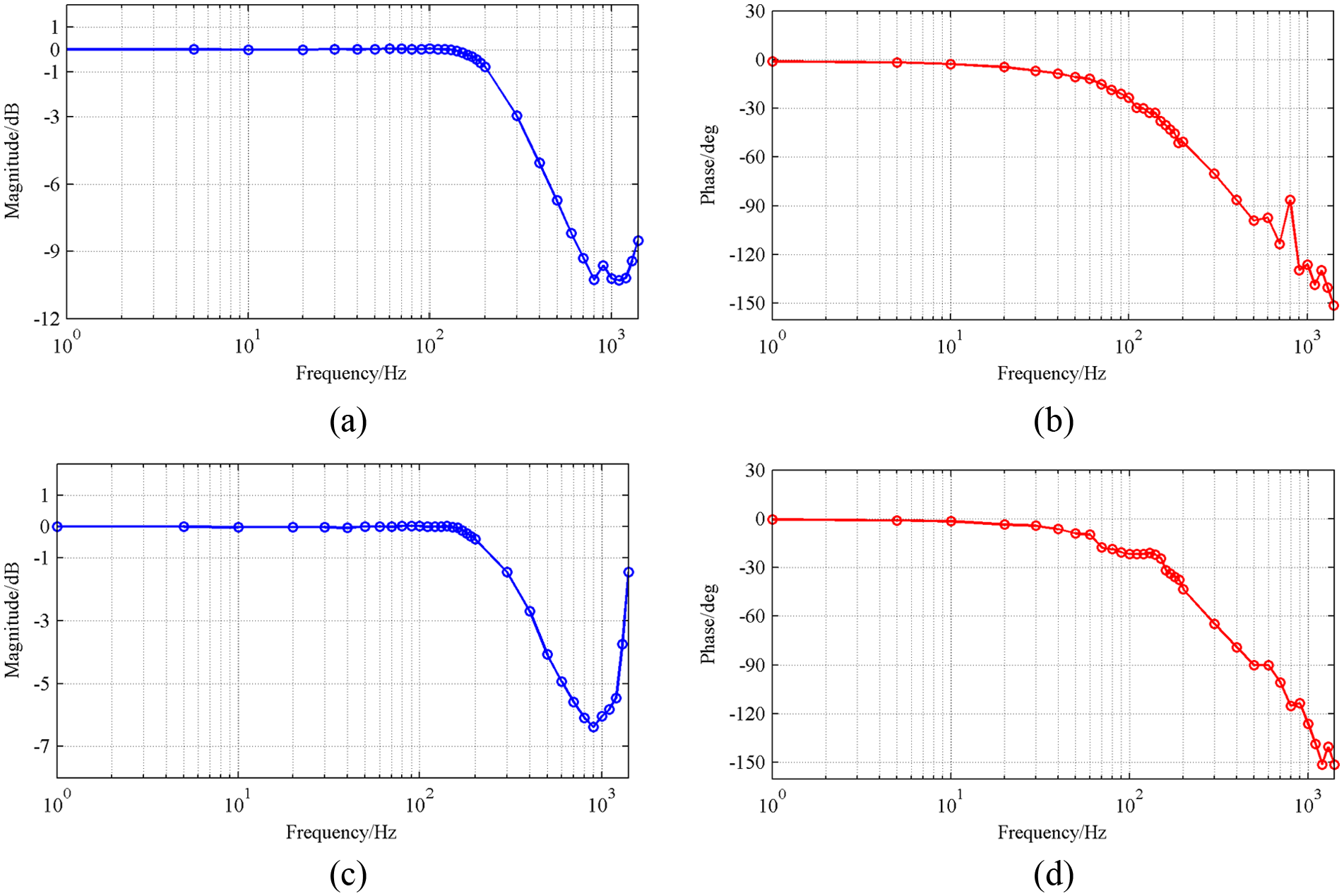
Frequency responses of the control system: (a) and (b) the results in the x-axis; (c) and (d) the results in the y-axis.
To discover the two-axis cooperative tracking performance of the 2-DOF micro-motion stage, a circular trajectory test is performed with different input rates for a circle of 5-µm radius centered at the workspace. The sinusoidal signals are adopted to generate circle trajectory. The output platform can be forced into a circular trajectory by driving it in the x-axis and y-axis with the appropriate amplitudes and phase quadrature (shifted in phase by 90°), and the input signals along the y-axis and x-axis can be expressed as


where A is the maximum amplitude of the input sinusoidal signals and f is the input frequency of the input sinusoidal signals.
Tracking performance tests for circle trajectories with the input frequencies of 0.5, 30, 60, and 100 Hz are illustrated in Figure 13. The sampling frequency used for feedback control is set to 20 kHz. Due to the closely matched dynamic characteristics of the axes, there is no elliptical distortion of circular motion at high input frequencies. It shows that less time is required to complete the circular trajectory with the rising of the input frequencies, and it increases the tracking error. Figure 13(a) and (b) shows that the actual trajectory obtained by experiment and the desired trajectory almost coincide, and the tracking error is below 5 nm with the input frequency of 0.5 Hz. Figure 13(c) and (d) demonstrates that the actual circular trajectory matches well with the desired circular trajectory, and the tracking error is not more than 60 nm with the input frequency 30 Hz. The tracking error increases to 100 nm when the input frequency is stable at 60 Hz. Considering the 5-µm radius, the error is just 2%. In contrast, the tracking error soar to 220 nm with the input frequency of 100 Hz, and the error is 4.4%. The tracking error occurring at the higher input frequency 100 Hz results in an expand shape of the circle, as shown in Figure 13(g), which is mainly caused by the worse tracking at the peak and valley points of the sinusoidal signals during higher frequency tracking trajectory, and the tracking errors are not uniformly distributed over a period.

Tracking performance for circle trajectories under various input frequencies: (a), (c), (e), and (g) the tracking results at 0.5, 30, 60, and 100 Hz; (b), (d), (f), and (h) the tracking errors at 0.5, 30, 60, and 100 Hz.
Conclusion
In this article, a 2-DOF flexure-based micro-motion stage for two axes’ cooperative motion is designed, optimized, fabricated, and experimental tested. This stage is composed of several prismatic joints with symmetrical configuration to obtain the decoupled property. To obtain good tracking performance of two axes’ cooperative motion at relatively high frequency, the first resonance frequency is considered as the objective of the optimization. Finally, FEA is employed and a prototype of the stage is manufactured to validate the design and performance. The experimental results on the manufactured prototype indicate that the micro-motion stage has a workspace range of 19.53 µm × 19.07 µm with a frequency of 1987 Hz, and the cross-coupling ratio between two axes is less than 1%. Stepwise response tests indicate that the stage can resolve nanometer-level position very well. According to the results of high-frequency cooperative tracking performance experiments with a PI controller, high-precision circular trajectory tracking up to 100 Hz is obtained. In the future, this stage will be used to generate vibrations in the XY plane. The accelerometers could be installed on the output platform. It can provide a new automated system for testing of the accelerometer transverse sensitivity at relatively high frequencies.
Footnotes
Academic Editor: Xiaotun Qiu
Declaration of conflicting interests
The author(s) declared no potential conflicts of interest with respect to the research, authorship, and/or publication of this article.
Funding
The author(s) disclosed receipt of the following financial support for the research, authorship, and/or publication of this article: This work was supported by the National Basic Research Program of China (Grant No. 2011CB302400), the National Science Foundation of China (Grant No. 51275260), and the National Science and Technology Major Project of China (Grant No. 2015ZX04014021 and Grant No. 2015ZX04001002).