
Abstract
This article presents thermal performance analysis, flow visualization, and heat transfer characteristic in a round tube heat exchanger inserted with wavy V-rib. The novel design of the wavy V-rib not only allows mass production and simple installation in the heating system but also remains the thermal performance and the heat transfer rate as near as those of the V-baffle design. The numerical investigation with finite volume method is selected to study and describe the mechanisms in the test section. The effects of rib thickness, rib height, and flow direction are considered for the turbulent regime. The numerical results are reported in terms of flow structure and heat transfer behavior. The relationship of the Nusselt number, friction factor, and thermal enhancement factor with various parameters is also concluded. The numerical results reveal that the optimum thermal performance is detected for the wavy V-rib at b/D around 0.1–0.15, while the optimal t/D is around 0.15–0.20 when considered at the simplicity of the wavy V-rib production.
Introduction
Thermal performance improvement in heat exchangers has been done using vortex generators or turbulators. Rib, winglet, baffle, twisted tape, and roughness surface are types of the vortex generators which are inserted in the heating or cooling systems to enhance heat transfer rate and thermal performance. The vortex flow and swirling flow which are created by the vortex generators are reason for heat transfer enhancement. The development of the vortex generators had been done by many researchers. The development depends on many factors such as vortex generator production, vortex generator installation, application of the heat exchanger, and maintenance.
The inclined and V-shaped baffles (thin rib) inserted in the heating tube/channel heat exchanger were investigated.1–9 The influences of the flow attack angle, baffle height, pitch spacing, and baffle shape were considered. The numerical investigation was selected to study the problems as it can report the results in terms of flow visualization and heat transfer characteristic. The understanding of mechanisms in the test section can help to design the new configuration of the vortex generators and the compact heat exchanger. As the numerical results, the researchers reported that the V-shaped baffle gives high effectiveness on thermal performance improvement. The V-shaped and inclined baffles can produce the vortex flow or swirling flow in the heating section that helps to augment heat transfer rate and thermal performance. However, it is difficult to produce and install the V-shaped and inclined baffles in the real system.
The winglet-type vortex generators were inserted in the heating or cooling systems to improve heat transfer rate and performance.10–16 The parameters, such as configuration, flow attack angle, and winglet spacing, of the winglet vortex generators were investigated using both numerical and experimental methods. The researchers concluded that the winglet vortex generators can produce the longitudinal vortex flow and disturbs the thermal boundary layer on the heating wall, which increase the heat transfer rate and thermal performance of the heat exchanger.
The wavy surface was selected to augment thermo-hydraulic performance in the fin-and-tube heat exchangers 17–28 and on the channel surface.29–32 The numerical and experimental investigations were carried out to analyze the problems. The distinctive point of the wavy surface is the low pressure loss in the system and uncomplicated fabrication.
In this investigation, the V-shaped rib is combined with the wavy surface called “wavy V-rib.” The wavy V-rib is inserted in the round tube heat exchanger to produce the vortex flow and disturb the thermal boundary layer on the heating surface. The influences of the rib height, rib thickness, and flow direction are considered for the turbulent regime, Re = 3000–10,000. The wavy V-rib may give the thermal performance similarly as the V-shaped baffle. Moreover, the fabrication and installation of the wavy V-rib are easier than the V-shaped baffle.
Physical model
A circular tube heating system inserted with wavy V-ribs is presented in Figure 1. The tube diameter is equal to 0.05 m. The thin-smooth plate is molded with the rectangular profile like V-rib called “wavy V-ribs.” The flow attack angle of the wavy V-ribs is fixed for all cases around 45°. The spacing between rectangular profiles is set around 1D (P/D = 1) in all the investigated cases. The height of the wavy V-ribs is presented with b, while the thickness of the rectangular profile for the wavy V-rib is shown with t. The variations in the height and thickness of the rectangular profile for the wavy V-rib are presented as b/D and t/D, respectively. The turbulent flow is considered for the current investigation with the Reynolds number Re = 3000–10,000. The b/D and t/D are varied; b/D = 0.05–0.20 and t/D = 0.05–0.20. The flow directions through the test section are separated into two directions: V-tip pointing downstream is called “V-Downstream,” while opposite direction is called “V-Upstream.”

Round tube heat exchanger inserted with wavy V-rib.
Boundary condition and assumption
The circular tube wall is set with the constant heat flux around 600 W/m2. The wavy V-rib plate is applied with zero heat flux (insulator). The periodic conditions on flow and heat transfer are applied for start and end planes of the computational domain. No-slip wall condition is used for the tube wall as well as wavy plate.
The flow is turbulent and incompressible. The flow and heat transfer are steady in three dimensions. The test fluid is air at 300 K with Prandtl number around 0.707. The air flows into the circular tube with uniform mass flow rate. The fluid properties are assumed to be constant at the average bulk temperature. The forced convection heat transfer is considered, while the natural convection and radiation heat transfer are ignored. The body-forced viscous dissipation is not measured.
Mathematical foundation and numerical method
The incompressible turbulent flow with steady operation in three dimensions and heat transfer characteristics in the square duct agree governed by continuity, Navier–Stokes, and energy equations. The realizable k–ε turbulent model with enhanced wall treatment is used to solve the present problem 33
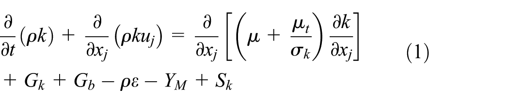
and

where

the constants in the model are given as follows

Gk and Gb are the generation of turbulence kinetic energy due to the mean velocity gradients and buoyancy, respectively. YM is the contribution of the fluctuating dilatation incompressible turbulence to the overall dissipation rate. Sk and Sε are user-defined source terms. σk and σε are the turbulent Prandtl numbers for k and ε, respectively.
The second-order upwind (SOU) numerical scheme is selected for all governing equations, decoupling with the SIMPLE algorithm using a finite volume method with FLUENT code. The solutions are measured to be converged when the normalized residual is less than 10−9 and 10−5 for the energy equation and the other variables, respectively.
The main parameters studied in this investigation are Reynolds number (Re), friction factor (f), Nusselt number (Nu), and thermal enhancement factor (TEF). The Reynolds number is calculated from equation (5)

ρ, μ, and u0 are density, viscosity, and inlet velocity of the fluid, respectively, while D is the diameter of the round tube.
The friction factor is defined as

where
The local Nusselt number is computed by

where hx is the local heat transfer coefficient based on bulk temperature and k is the thermal conductivity of the air.
The average Nusselt number can be printed by

where A is the heat transfer area of the tube heat exchanger.
Thermal performance enhancement factor (TEF) is defined as the ratio of the heat transfer coefficient of an augmented surface h to that of a smooth surface h0 under the constant pumping power condition. The TEF can be expressed as follows

The f0 and Nu0 are the friction factor and the Nusselt number of the smooth tube, respectively.
Numerical validation
The computational domain of this research is validated with the main aim to assure that the numerical result has reliability and high accuracy. The numerical validations are classified as follows: validation of the smooth tube, turbulent model validation, and grid independence.
Figure 2 presents the validations of the smooth round tube 34 with no wavy V-rib with respect to the Nusselt number and friction factor. The turbulent models, SST k–ω and realizable k–ε, are also compared. The numerical result indicates that the deviations of the Nusselt number and friction factor are around 4% and 12%, respectively, when solved the problem with realizable k–ε turbulent model.
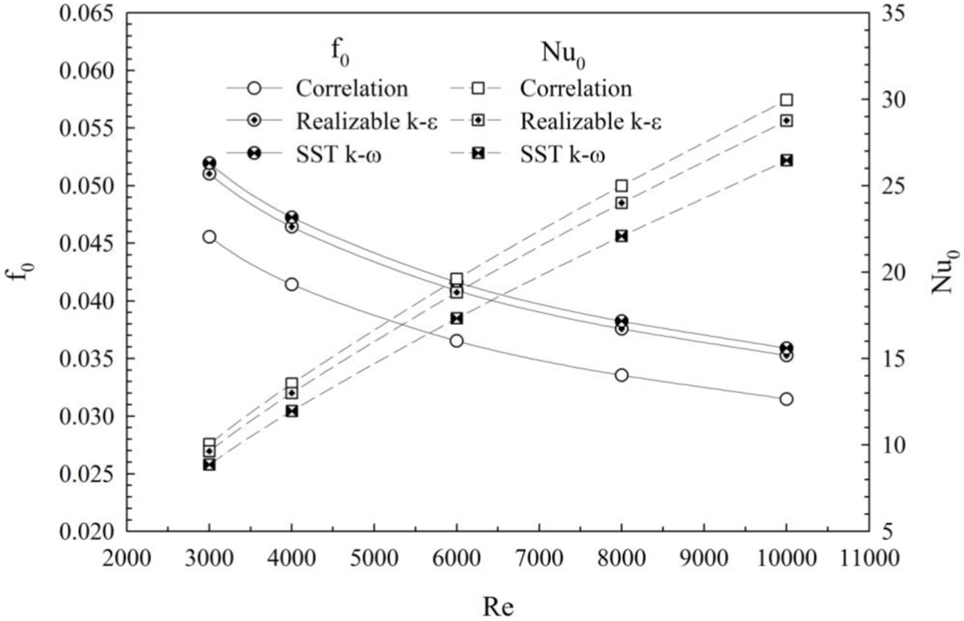
Validation of the smooth tube with respect to heat transfer and friction factor.
The verification of grid independence for the computational domain is reported in Figure 3. The wavy V-rib with b/D = t/D = 0.15 for V-Downstream is selected to test in this part. The five sets of grid cell—80,000, 120,000, 180,000, 220,000, and 280,000—are compared with respect to both heat transfer rate and friction loss. The results reveal that the optimal grid cell is found at grid around 180,000 cells when both time to investigate and accurate results are considered. The grid around 180,000 is selected to create all domains in this investigation. As the preliminary study, it can be concluded that the creation domain is reliable to predict flow and heat transfer mechanisms in the round tube heat exchanger inserted with wavy V-rib.

Grid independence.
Numerical results
The mechanisms on flow and heat transfer in the circular tube heat exchanger inserted with wavy V-rib are reported. The understanding of the mechanism in the test tube is an important point to help to improve the thermal performance of the cooling of heating processes. Moreover, the influences of the b/D, t/D, flow direction, and Reynolds number are also presented. The numerical results are divided into three sections: flow and heat transfer profiles, influence of b/D, and influence of t/D.
Flow topology and heat transfer characteristics
The configurations of flow in the test section inserted with wavy V-rib plate are displayed with tangential velocity vectors in transverse sections and longitudinal flow along the test tube. Figure 4(a) and (b) plots the tangential velocity vectors in transverse sections of the tube heat exchanger inserted with wavy V-rib at t/D = b/D = 0.15 and Re = 6000 for V-Downstream and V-Upstream, respectively. The vortex flows are found through the test section for both cases. The vortex flows are an important factor to enhance heat transfer rate in the heating section. The vortex flows disturb the thermal boundary layer on the tube surface and help to blend the temperature of the air flow, which are the important phenomena to enhance the heat transfer rate and thermal performance over the plain tube. The four main vortex flows are detected in all sections. The symmetry pattern of the flow is found in left and right parts of the plane due to rib symmetry. Considering the lower pair of the vortex flow, the counter rotating flow with common-flow-down and common-flow-up is detected for V-Downstream and V-Upstream arrangements of the rib, respectively. The details of the tangential velocity vector in cross-sectional planes are plotted in Figure 5.
Tangential velocity vector in y–z planes for the tube inserted with wavy V-rib at b/D = t/D = 0.15 and Re = 6000: (a) V-Downstream and (b) V-Upstream.
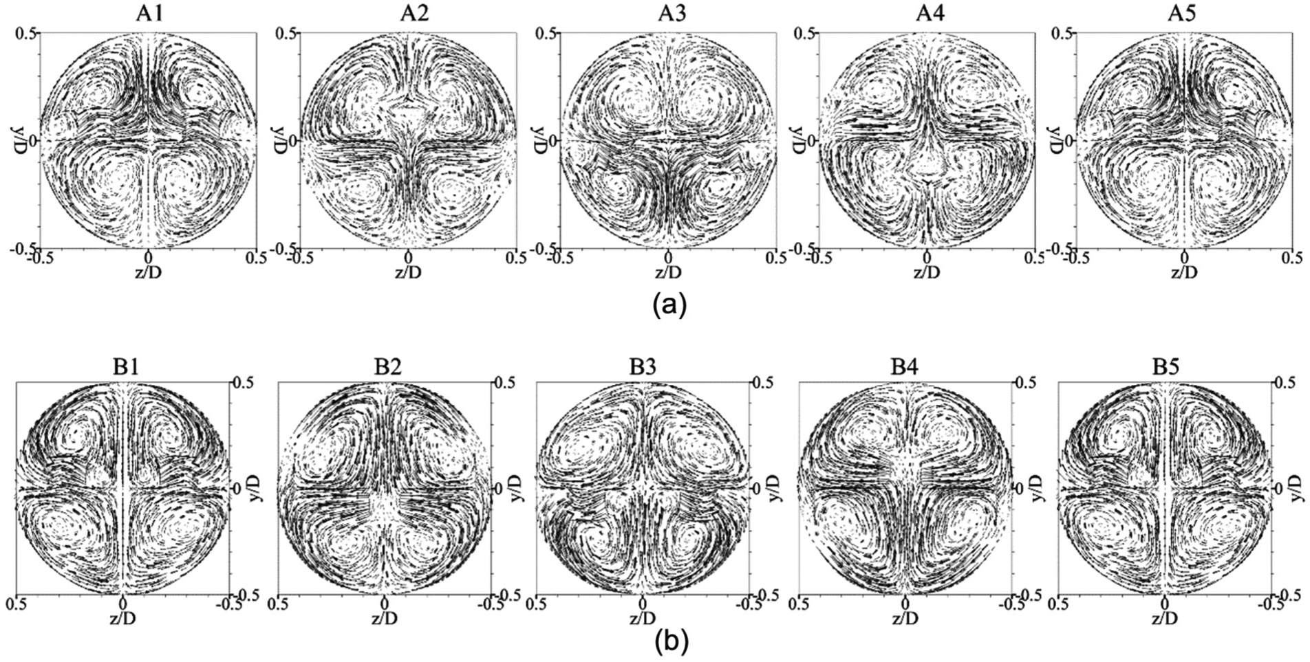
Details of the tangential velocity vector in y–z planes for the tube inserted with wavy V-rib at b/D = t/D = 0.15 and Re = 6000: (a) V-Downstream and (b) V-Upstream.
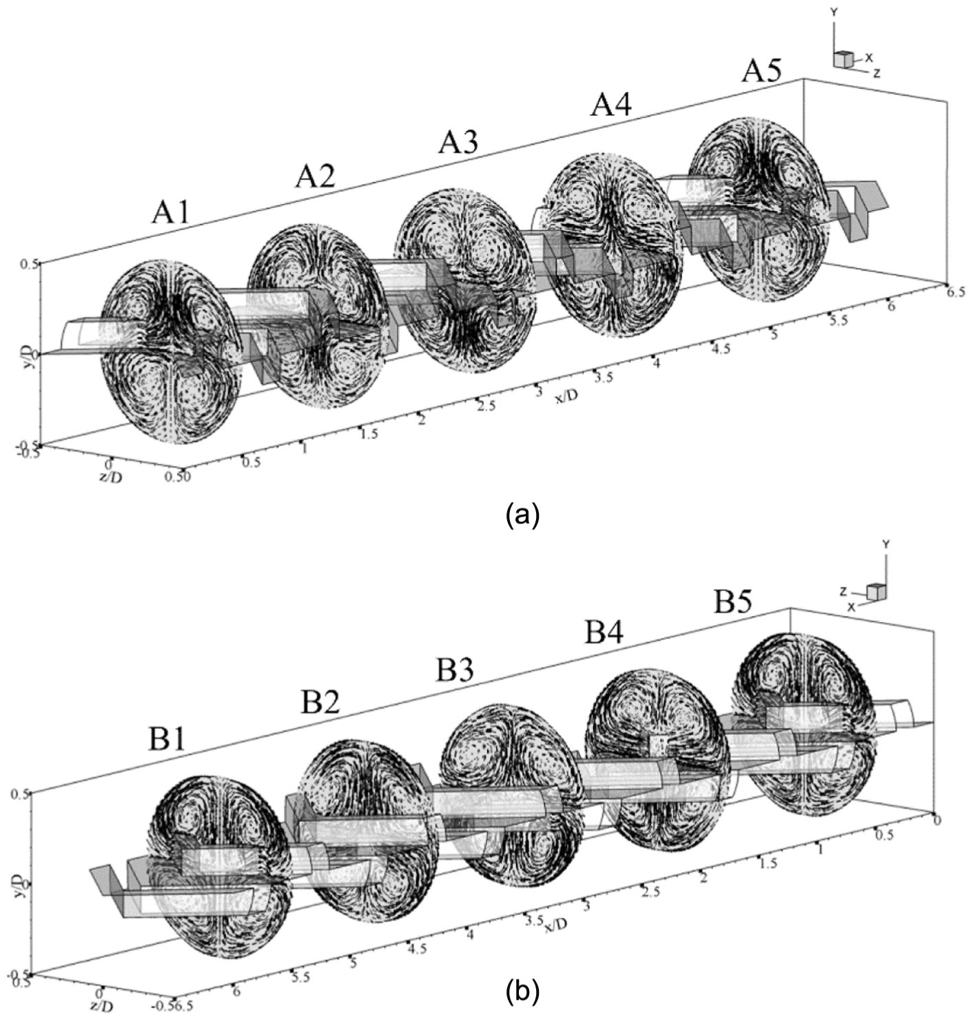
The longitudinal vortex flows in the round tube heat exchanger inserted with wavy V-rib are reported in Figure 6(a) and (b) for V-Downstream and V-Upstream arrangements, respectively. The symmetry flow pattern on the left and right parts of the test tube is found in both cases due to the rib symmetry. For V-Downstream case, the air flows across the ribs and after that slides on the tube wall and on the rectangular groove before moving to the next module. For V-Upstream arrangement, the air flows to the V-tip and then slides on the wavy rib on the tube surface and moves to the next module.
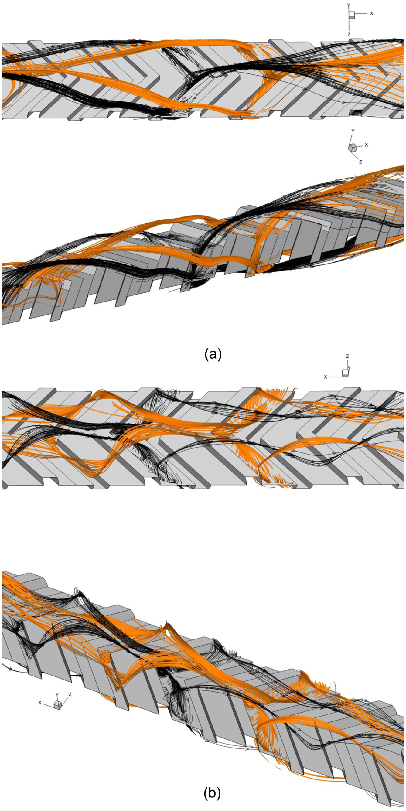
Longitudinal vortex flow for the tube inserted with wavy V-rib at b/D = t/D = 0.15 and Re = 6000: (a) V-Downstream and (b) V-Upstream.
The heat transfer behaviors in the round tube heat exchanger are presented in terms of turbulent kinetic energy (TKE) in transverse planes, temperature distribution in y–z planes, and local Nusselt number distribution on the tube wall. Figure 7(a) and (b) reports the turbulent kinetic energy in transverse planes of the round tube inserted with wavy V-rib for V-Downstream and V-Upstream arrangements at Re = 6000 and t/D = b/D = 0.15, respectively. The turbulent kinetic energy in transverse planes can help to describe the strength of the flow in the test tube. The high TKE is depicted with red contour, while the opposite trend is plotted with blue contour. For V-Downstream, the high TKE is detected at the upper zone and left–right zones of the V-rib. For V-Upstream, the high TKE is clearly found behind the V-rib.

Turbulent kinetic energy in y–z planes for the tube inserted with wavy V-rib at b/D = t/D = 0.15 and Re = 6000: (a) V-Downstream and (b) V-Upstream.
The temperature distributions in transverse planes of the heating tube inserted with wavy V-rib are shown in Figure 8(a) and (b) for V-Downstream and V-Upstream cases at Re = 6000 and t/D = b/D = 0.15, respectively. The temperature contours can describe the disturbance of the thermal boundary layer on the tube wall and fluid mixing behavior in the test tube. The high fluid temperature is represented by red layer, while the low fluid temperature is represented by blue layer. In general, the red and blue layers are found near the tube wall and the core of the test section, respectively, for the smooth tube with no generators. The better fluid mixing is detected when the wavy V-rib was inserted in the heating tube. The red layer near the tube wall is found to be thinner, while the blue layer spreads out from the tube core. The wavy V-rib with V-Upstream arrangement gives better temperature distribution than the V-Downstream case.

Temperature distribution in y–z planes for the tube inserted with wavy V-rib at b/D = t/D = 0.15 and Re = 6000: (a) V-Downstream and (b) V-Upstream.
The local Nusselt number distributions on the tube wall heat exchanger are reported as shown in Figure 9(a) and (b), respectively, for V-Downstream and V-Upstream arrangements at Re = 6000 and t/D = b/D = 0.15. The red contour means the better heat transfer rate, while the opposite result is presented with blue contour. The heat transfer rate in the test section is found to be better when the wavy V-rib was inserted. The best distribution of the Nusselt number contour is detected at the upper–lower curves of the V-Downstream rib, while the V-Upstream rib performs higher heat transfer rate at left–right curves of the tube heat exchanger. It is noted that the heat transfer behavior directly relates with the flow configuration. The impinging point of the fluid flow (high strength of the thermal boundary layer disturbance) is the best region for heat transfer enhancement.
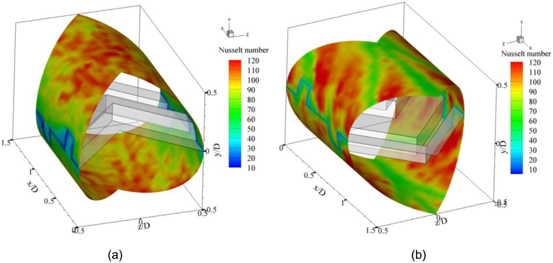
Local Nusselt number distributions for the tube inserted with wavy V-rib at b/D = t/D = 0.15 and Re = 6000: (a) V-Downstream and (b) V-Upstream.
Influence of b/D
The influences of b/D or rib height are concluded with the relations of the Nusselt number ratio (Nu/Nu0), friction factor ratio (f/f0), and thermal enhancement factor (TEF) with Reynolds number. The variations in the Nu/Nu0 with Re at various b/D and arrangements are reported as shown in Figure 10(a)–(d), respectively, for t/D = 0.05, 0.10, 0.15, and 0.20. In general, the Nu/Nu0 tends to decrease with the increase in the Reynolds number in all investigated cases. The heat transfer rate increases when augmenting the height of the rib. At b/D = 0.20, the heat transfer rate is highest, while the b/D = 0.05 provides the reverse result for both arrangements. This is because the b/D = 0.20 can generate the strongest vortex flow to disturb the thermal boundary layer on the heat transfer surface, which results in the highest heat transfer rate. In addition, the b/D = 0.20, 0.15, and 0.10 give higher heat transfer rate than the b/D = 0.05 around 21.47%–48.22%, 31.86%–94.67%, and 50.10%–136.58%, respectively, depending on t/D and Re values.

Variations in the Nu/Nu0 with Re for (a) t/D = 0.05, (b) t/D = 0.10, (c) t/D = 0.15, and (d) t/D = 0.20.
The insertion of the wavy V-rib in the tube heat exchanger not only increases the heat transfer rate, but also increases the pressure loss. The pressure loss in the test section can describe the friction factor ratio. Figure 11(a)–(d) reports the variations in the f/f0 with Re at various b/D and rib arrangements for t/D = 0.05, 0.10, 0.15, and 0.20, respectively. Generally, the f/f0 slightly increases when enhancing Re for all studied cases. The enhancement of the f/f0 is due to the augmentation of the rib height. The b/D = 0.20 gives the highest friction loss, while the b/D = 0.05 results in the opposite trend. This is because the b/D = 0.20 gives the lowest flow area when considered in cross-sectional area. The b/D = 0.20, 0.15, 0.10, and 0.05 provide the friction factor ratio around 60.11–114.83, 33.57–51.15, 15.25–21.80, and 5.97–8.67, respectively, depending on t/D and Re.

Variations in the f/f0 with Re for (a) t/D = 0.05, (b) t/D = 0.10, (c) t/D = 0.15, and (d) t/D = 0.20.
The efficiency of the tube heat exchanger inserted with wavy V-rib is reported in terms of thermal enhancement factor or TEF, which is calculated from the ratio of the Nusselt number and friction factor at similar pumping power. Figure 12(a)–(d) shows the variations in the TEF with Re at various b/D for V-Downstream and V-Upstream arrangements of t/D = 0.05, 0.10, 0.15, and 0.20, respectively. In general, the TEF decreases with the increase in the Reynolds number for all cases. Almost in all cases, the thermal performance of the round tube inserted with the wavy V-rib is higher than that of the smooth tube with no wavy V-rib (TEF > 1). The optimum TEF is detected at b/D = 0.10 for V-Upstream and at b/D = 0.10 and 0.15 for V-Downstream. In addition, the TEF is around 0.90–2.20 depending on b/D, t/D, and Re.

Variations in the TEF with Re for (a) t/D = 0.05, (b) t/D = 0.10, (c) t/D = 0.15, and (d) t/D = 0.20.
Influence of t/D
The effects of the rib thickness or t/D on heat transfer, friction loss, and thermal efficiency are concluded in terms of the relationship of the Nu/Nu0, f/f0, and TEF with t/D. Figure 13(a)–(d) reports the variations in the Nu/Nu0 with t/D at various Re and flow directions for b/D = 0.05, 0.10, 0.15, and 0.20, respectively. For b/D = 0.05 and 0.10, the change in the t/D has a few effect on heat transfer behavior, except Re = 3000–6000 for V-Upstream case, which gives higher heat transfer rate when increasing t/D. For b/D = 0.15 and 0.20, the Nu/Nu0 of the V-Upstream arrangement is found equally in all t/D values, while the Nu/Nu0 for the V-Downstream case slightly drops when increasing t/D. The t/D = 0.05, 0.10, 0.15, and 0.20 produces the heat transfer rate around 2.57–8.11, 2.59–8.04, 2.57–7.70, and 2.60–7.74 times above the smooth round tube, respectively.

Variations in the Nu/Nu0 with t/D for (a) b/D = 0.05, (b) b/D = 0.10, (c) b/D = 0.15, and (d) b/D = 0.20.
Figure 14(a)–(d) presents the variations in the f/f0 with the t/D at various Re and flow directions for b/D = 0.05, 0.10, 0.15 and 0.20, respectively. The highest friction loss is found at t/D = 0.20 for b/D = 0.05 on both V-Downstream and V-Upstream arrangements. For b/D = 0.10, the similar trend as b/D = 0.05 is detected for V-Upstream case, while the friction loss of the V-Downstream case is found nearly when changing t/D. The lowest f/f0 is found at t/D = 0.20 for all Reynolds numbers of V-Upstream and for Re = 3000–6000 at b/D = 0.15 and 0.20. The friction factor ratio of the tube heat exchanger inserted with various t/D of the wavy V-rib is around 5.97–102.96, 6.37–107.49, 6.30–114.83, and 6.62–94.21 for t/D = 0.05, 0.10, 0.15, and 0.20, respectively.

Variations in the f/f0 with t/D for (a) b/D = 0.05, (b) b/D = 0.10, (c) b/D = 0.15, and (d) b/D = 0.20.
Figure 15(a)–(d) displays the relations of the TEF with t/D at various cases of b/D = 0.05, 0.10, 0.15, and 0.20, respectively. In general, the variations in t/D have a few effect on TEF value, except for b/D = 0.05, Re = 3000–6000, and V-Upstream, which provides the peak of thermal performance at t/D = 0.20. In the range studies, the optimum TEF is around 2.17, 2.16, 2.16, and 2.18 for the heating tube with wavy V-rib at t/D = 0.05, 0.10, 0.15, and 0.20, respectively.

Variations in the TEF with t/D for (a) b/D = 0.05, (b) b/D = 0.10, (c) b/D = 0.15, and (d) b/D = 0.20.
The correlations of the Nu/Nu0 and f/f0 for the tube heat exchanger inserted with wavy V-rib (b/D = 0.05–0.20, t/D = 0.05–0.20, α = 45°, and Re = 3000–10,000) are reported as shown in Figures 16 to 17.

Correlations of the Nu/Nu0 for (a) V-Downstream and (b) V-Upstream.

Correlations of the f/f0 for (a) V-Downstream and (b) V-Upstream.
Conclusion
Thermohydraulic performance improvement in a round tube heat exchanger fitted with wavy V-rib plate is investigated numerically in three dimensions. The influences of rib height, rib thickness, and flow direction on heat transfer and thermal performance are considered for turbulent regime (Re = 3000–10,000). The mechanisms of flow and heat transfer when wavy V-rib was inserted in the heating tube are stated. The conclusion for this investigation is reported as follows.
The heat transfer rate and thermal performance in the heating system are enhanced due to the insertion of the wavy V-rib. The wavy V-rib disturbs the thermal boundary layer near the tube wall and brings a better fluid temperature distribution.
The enhancement of rib height for the wavy V-rib increases both heat transfer rate and friction loss in the test tube. The optimum rib height is found around b/D of 0.10–0.15 when the augmentations on the heat transfer rate and friction loss at similar pumping power are considered.
The increment of the rib thickness can reduce the pressure loss at b/D = 0.15 and 0.20, but has a few effect for heat transfer rate and thermal enhancement factor. The suggested thickness of the wavy V-rib for this study is around t/D = 0.15–0.20 as the production process in this range is more convenient than the thin rib (t/D < 0.15).
The novel design of the wavy V-rib allows mass production and simple installation in the heating system. The uncomplicated process of both installation and maintenance can help to save time and cost for the operation.
The comparison of the thermal enhancement factors of this work with those of the previous researches, such as wavy rib, 35 discrete combined baffle, 36 V-baffle, 37 and discrete-full baffle, 38 is presented in Figure 18. It is found that the wavy V-rib gives higher thermal performance than the other turbulators when considered at Re = 3000.

Comparison of the thermal enhancement factor with previous works.
Footnotes
Appendix 1
Acknowledgements
The researchers would like to thank Associate Prof. Dr Pongjet Promvonge for suggestions.
Academic Editor: Oronzio Manca
Declaration of conflicting interests
The author(s) declared no potential conflicts of interest with respect to the research, authorship, and/or publication of this article.
Funding
The author(s) disclosed receipt of the following financial support for the research, authorship, and/or publication of this article: This research was funded by the College of Industrial Technology, King Mongkut’s University of Technology North Bangkok (Grant No. Res-CIT0208/2017).