
Abstract
Based on branch substructure method, this article deduces motion equation of an equipment–structure–soil interaction system. The equation is converted and applied to a shaking table real-time substructure experiment. The equipment–structure system is adopted as experimental substructure loaded by the shaking table. Meanwhile, finite element model of soil is adopted as numerical substructure after modal reduction. An equipment–structure–soil interaction scale model is designed and tested using shaking table under different earthquake records. Comparison shows good agreement of results of experimental and finite element methods. This work also proves validity and accuracy of the proposed experimental method.
Keywords
Introduction
Nonstructural components, such as equipment, account for increasing percentages in current building systems, thus forming equipment–structure systems. Damage to precision equipment can cause serious safety hazards and economic losses. For instance, nonstructural damage accounted for 50% of economic losses of the 1994 Northridge Earthquake. Li et al. 1 and Pantoli et al. 2 conducted a shaking table test of equipment–structure systems to study earthquake responses of structures and equipment. Researchers observed interactions, when ignored under some conditions, may adversely impede seismic design of structures and equipment. The current equipment–structure system research is, generally, based on the assumption of rigid foundation without consideration for soil effect. Practical engineering situations cannot be reflected by seismic research on equipment–structure systems based on the rigid foundation assumption. Jiang and Xu 3 and Jiang and Li 4 conducted a shaking table test of soil–structure interaction systems and discovered that soil–structure interactions significantly influence superstructural responses. Accounting for deformation of soil and foundation, full-coupled soil-structure shaking table tests5–8 and numerical analysis9–12 were conducted and gained deeper insight into the seismic performance of structures. With soil intervention, vibration period of the whole model extends and thus influences authentic seismic responses of superstructures. Calculation results may seriously deviate from practical situations. Research limitations increase the need for experimental studies on equipment–structure–soil interaction systems. Meanwhile, the traditional experimental method, which is used to construct the entire equipment–structure–soil model, is complex and costly. Thus, a practical experimental method should be developed to efficiently and accurately study equipment–structure–soil interactions. An ideal experimental method can help provide valuable references for the seismic design of structures and equipment.
Real-time substructure experimental method realizes large-scale complex experiments. The method was proposed by Nakashima et al. 13 and divides the whole model into two parts, namely, experimental and numerical substructures. Major research objects act as experimental substructures, which are loaded and controlled by actuators. The remaining components serve as numerical substructures, which can effectively reduce experimental scale and difficulty by numerical calculation. Soil influence is considered in real-time substructure experimental research of shaking table. These researches adopt soil as numerical substructure and the superstructures as experimental substructure. Experimental and numerical substructures exchange data in real time and jointly evaluate dynamic responses of whole coupling systems. Considering real-time property, the present experiment aims to select simplified calculation model as numerical substructure. Simplified calculation models of such kind include the lumped parameter model adopted by Wang et al., 14 modified Penzien model adopted by Yan et al., 15 and single-degree-of-freedom (DOF) model adopted by Tang. 16 Simplified calculation models can meet the calculation efficiency requirements of substructure experiments for numerical substructure but may influence calculation accuracy of some complex soil models. Moreover, finite element models contain too many DOFs and need long computing time. So, finite element models may not satisfy the real-time requirement and cannot be directly allowed to implement real-time substructure testing. Jiang and Yan 17 and Wang and Jiang 18 conducted in-depth research on soil–structure interaction systems using the branch substructure method. The scholars succeeded in decreasing calculation quantity through modal reduction of soil.
Using the branch substructure method proposed in the literature, 17 this article derives, transforms, and applies motion equation of an equipment–structure–soil interaction system to a shaking table real-time substructure experiment. An equipment–structure–soil interaction scale model is designed, in which the structural model features a four-story steel frame and the equipment is simplified into a single-DOF model. The equipment–structure system is adopted as experimental substructure, which is loaded and controlled by the shaking table. Meanwhile, soil acts as numerical substructure, which is calculated by the simulation software. Feasibility of proposed experimental method is verified. Based on the experimental results, this work compares seismic responses of the equipment and structure with and without consideration for soil influence.
Shaking table real-time experimental method based on branch substructure method
The equipment–structure–soil interaction system comprises three parts: equipment, structure, and soil. The shaking table loads and controls the equipment–structure system, which is adopted as experimental substructure. Soil serves as numerical substructure, which is calculated and analyzed by simulation software. The two substructures exchange data in real time. Based on branch substructure method, Figure 1(a) shows division of equipment–structure–soil interaction system into branch d (equipment–structure rigid system on elastic soil) and branch s (equipment–structure deformed system on rigid soil), as shown in Figure 1(b) and (c), respectively. The “elastic” and “rigid” parts are defined without overlapping deformation between branches according to the branch substructure method.
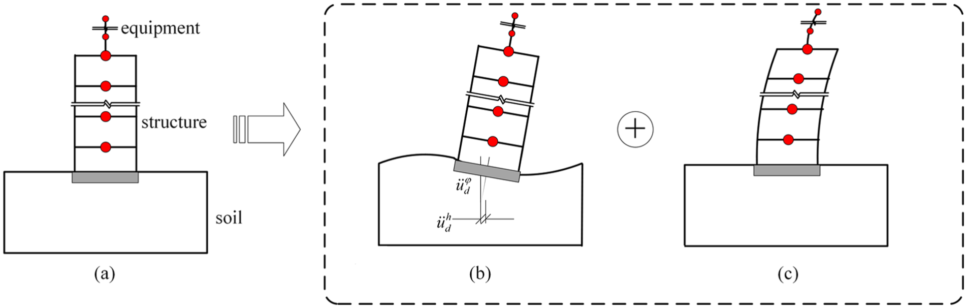
Schematic diagram for motion equation of equipment–structure–soil interaction systems: (a) equipment–structure–soil interaction system, (b) equipment–structure rigid system on the elastic soil, and (c) equipment–structure deformed system on the rigid soil.
Equation (1) shows the characteristic equation of soil in branch d. In the equation, kd and md represent the stiffness matrix and the mass matrix of soil in branch d, respectively. λd represents the eigenvalues of soil in branch d. Modal transformational matrix Φ
d
of soil in branch d, which is composed of m-order modes, can be obtained as follows, where

Equation (2) shows the computing matrix of branch d after modal transformation. ud corresponds to the physical displacement coordinate of soil in branch d, qd represents the modal coordinate of soil in branch d, cd stands for damping matrix of soil in branch d and can be obtained through general damping theory, and fd represents the load matrix of branch d

The equipment–structure system contains several DOFs. Thus, this system does not conduct modal reduction and maintains completeness of calculation matrix. Displacement us of equipment–structure system comprises two parts. The first part is the rigid-body displacement caused by soil displacement, as shown in Figure 1(b). The second part corresponds to self-displacement qs shown in Figure 1(c) (equation (3))

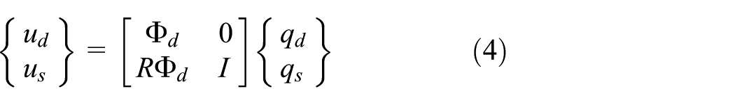
where R represents the displacement transformation matrix of equipment–structure system and it can be obtained based on coordinate relationship of deformation in branch d. Displacement of equipment–structure system and soil can be written in the following matrix form
In accordance with coordinate relationship of deformation, equation (5) presents the motion equations for equipment–structure–soil interactions

where ms, cs, ks, and fs correspond to the mass matrix, damping matrix, stiffness matrix, and load matrix, respectively, in the equipment–structure system in branch s. In mass matrix of overall motion equation of the system, coupling item msRΦ d connects the equipment–structure system and soil. To realize substructure experiments, load-related coupling item is shifted to the right side of overall motion equation. In this manner, equations (6) and (7) can be respectively obtained to represent motion equations for soil and equipment–structure system, as shown below


In shaking table substructure experiment, a single-DOF model is used as equipment in experimental substructure. The four-story steel frame can be simplified into a four-DOF shear model. In this manner, the equipment–structure system forms a five-DOF calculation model. Therefore, R can be expressed as equation (8). In this equation, R features a 5 × n matrix, where n represents the total DOF of soil, h1–h4 represents the story height of the structure, and h5 represents the height of the top of equipment

Same as in equation (7), Figure 2 shows the external and coupling loads on the right side of motion equations of the equipment–structure system.

Equivalent load transformation.
The following statements present the flow of the proposed real-time substructure experimental method for equipment–structure–soil interaction systems:
Assume that in step “i,” both the initial external and the coupling loads imposed on soil are known.
Calculate acceleration response of soil in Step “i+Δt.”
Obtain external and coupling loads imposed on the equipment–structure system.
Calculate equivalent horizontal acceleration on the basis of horizontal load equivalence principle, and use the new instruction to operate the shaking table. The equivalent load is imposed on the experimental substructure through the shaking table.
Calculate the acting force, which is generated by the experimental substructure, based on acceleration measurement data on the equipment–structure system and seismic excitation. Acting force is then transferred to soil to proceed to the next step of numerical calculation. In this manner, experimental data obtained by the shaking table test are exchanged with calculation data obtained by the simulation software in each step until conclusion of the experiments.
Experimental design
We design a one-fifth scale model of the equipment–structure–soil interaction system (Figure 3). The prototype structure is a four-story steel frame public building, and single-DOF-equipment model which imitates signal receiving equipment is placed on the roof of the frame. The equipment–structure system is adopted as experimental substructure, which is loaded and controlled by the shaking table. The soil is classified into site class III according to the Chinese national standards code, 19 with 115.7 m/s equivalent shear wave velocity and 75 m thickness of covering layer. This soil is adopted as numerical substructure in shaking table real-time substructure experiment. The similitude scale factors for test model are shown in Table 1.

Schematic design of the equipment–structure–soil interaction model.
Similitude scale factors for test model.

Experiments are conducted on a 3 m × 3 m shaking table in Beijing University of Technology. Earthquake records for El Centro, Tianjin, and PerSon are selected. On the basis of frequently occurring earthquake requirements of 8° seismic intensity, amplitude acceleration of earthquake motion is adjusted to 0.7 m/s2. Figure 4 presents the time history curves for acceleration of three earthquake records. Upon experiment, we measure acceleration responses of the central position of each story in the structure, equipment top, and shaking table surface.

Acceleration time history curves of three earthquake records.
Experimental substructure model
As shown in Figure 3, H steel is adopted in structural model of the equipment–structure system. In the model, the first story measures 0.68 m in height. The remaining stories stand 0.63 m tall. Longitudinal and transverse spans both measure 1.6 m. Total mass of the first to third stories equals 1700 kg, whereas the fourth story features a total mass of 1540 kg. Equipment model stands 0.5 m high, is designed with round steel pipe, and presents a total mass of 90 kg. Elasticity modulus and yield strength of structural materials measure 202.0 GPa and 339.6 MPa, respectively. Elasticity modulus and yield strength of equipment materials reach 192.0 GPa and 421.4 MPa, respectively. Four steel plates are attached to the bottom of structure columns while the steel plates are anchored to the shaking table using anchor bolts during testing. And the equipment is anchored to central position of the structure’s top story using anchor bolts during experiments.
Numerical substructure model
Table 2 shows the material parameters of foundation and soil, which acts as numerical substructure in this experiment. Overall dimensions of numerical substructure model measure 30 m × 15 m × 15 m, and dimensions of embedment foundation span 2.2 m × 2.2 m × 0.4 m. Given the high number of DOF, soil finite element model cannot meet real-time requirements of shaking table substructure experiment. Therefore, this study conducts modal reduction of soil finite element model in two steps. First, finite element software ANSYS is used to build the soil finite element model based on experimental design. 20 Second, programming software MATLAB is used to conduct modal reduction of finite element model. Specific calculation steps are shown below.
Parameters of foundation and soil materials.

Finite element modeling
Soil finite element model selects eight-node solid element. Each element node contains DOF in directions of x, y, and z axes. As per element division principle, element height is expressed as hmax = (0.200–0.125)λs, where λs represents the wavelength. Element width should conform to the inequality, bmax≤5(hmax). Experimental substructure model moves along the x direction, and soil model also generates horizontal deformation along the same path. Thus, constraint equations for soil finite element model should be simplified. Figure 3 shows the central cross section of soil finite element model. A built model reflects the relationship between DOF of central plane nodes and surrounding nodes. Taking any point, P, on central plane as example, point Q, a random point outside the central plane which equals x coordinate of point P, DOF of points P and Q satisfy the following equations:
Modal reduction method
Computing matrix of soil is first entered into MATLAB programming software. As major soil modes are discretely distributed, Li and Jiang 23 investigated the correlations between external loads and vibration characteristics of soil; they used the Ritz vector method to calculate soil modal vectors, which can filter out some vibration modes with slight influence on soil. This article also adopts this method for Ritz vector analysis. We calculate soil vibration mode and frequency of each order; calculation results are compared with complete modal calculation results for soil (see Table 3). According to code of seismic design of buildings, total participating mass ratio should be higher than 90%. In this article, the first 60 Ritz vectors participating mass ratio of soil are calculated. The sum of participating mass ratios reaches 0.95. Following the above method, we obtain the modal transformation matrix, Φ d , of the soil model. Equation (2) provides the computing matrix after modal reduction of soil finite element model. Through this method, DOF significantly reduces under the prerequisite of guaranteeing calculation precision of soil model. Using the model in numerical substructure analysis efficiently reduces calculation quantity of numerical substructure and improves calculation efficiency.
Feature parameters of soil.

Control procedures
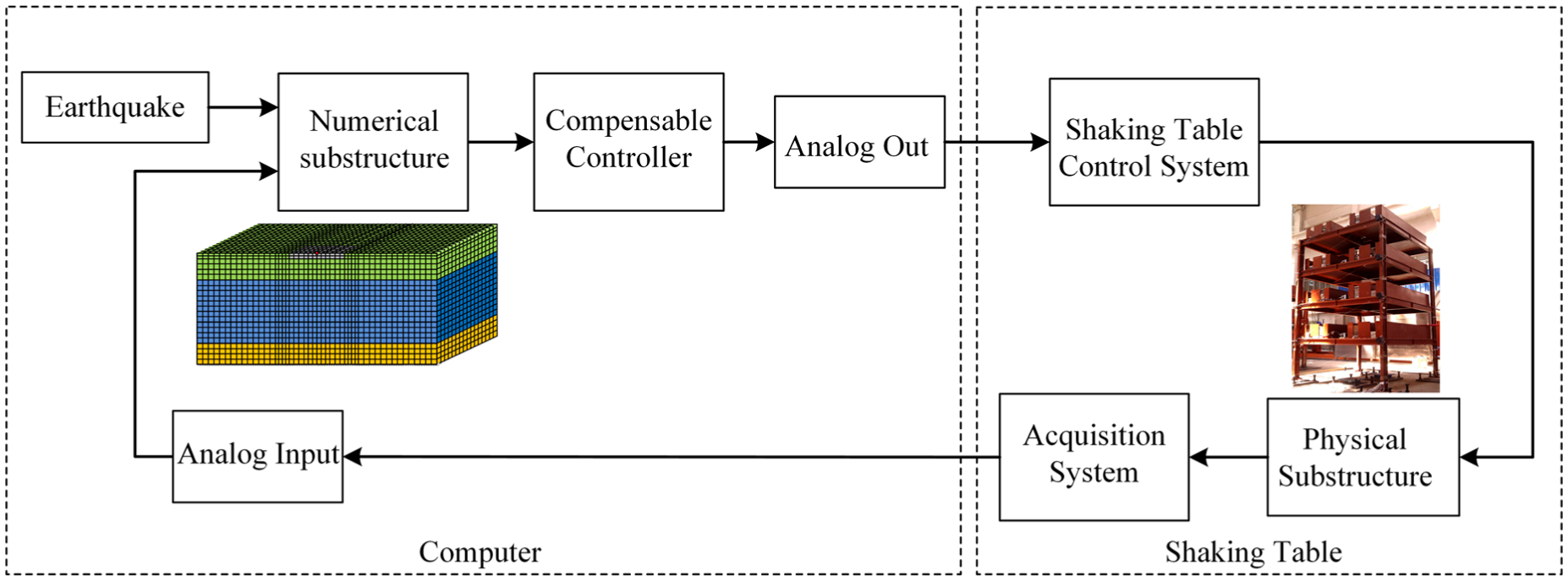
The composition of the experimental system is illustrated in Figure 5. Three steps are required for the shaking table real-time substructure experiment: (1) construction of real-time experimental system, (2) designing the substructure controller, and (3) calculating numerical substructure. This experiment uses computers for engineering control and servers for numerical substructure calculation. Simulink, a simulation software, is used for calculation of numerical substructure and controller design. Real-time Desktop 24 in Simulink tool kit can compile experimental modulus into the C code and operate it under real-time environment. A computer, a compiler, and an I/O device alone can turn the computer into a real-time system, communicate with external devices through I/O gadgets, and build a complete real-time substructure experimental system. The method provides a low-cost and effective approach for real-time substructure experiments.
Schematic diagram of the experimental system.
The substructure test requires actuators that can track input signals. For this, some control strategies are used for compensation. Delay compensation recognizes that dynamic characteristics of actuators can simplify pure-delay models, in which delay time of τ seconds exists between input and output signals. Single-step compensation25,26 and multistep compensation 27 are developed and applied to real-time substructure test. Due to complex dynamic characteristics of the shaking table, the pure-delay model cannot meet the requirements of control compensation. Inverse dynamic compensation strategy 28 can eliminate magnitude and phase errors of the shaking table after obtaining an accurate mathematical model representing its dynamic characteristics, as shown in Figure 6. As shown in the figure, input r and output y are given as y = C(s)G(st)r, whereas the controller C(s) equals the inverse dynamic model of shaking table G(st). Due to the influence of external environments, the inverse dynamic method is not constantly effective in controlling shaking tables.

Schematic diagram of open-loop inverse dynamic control.
Based on this conception, inverse dynamic compensation via simulation (IDCS)29–31 is developed and used to control nonlinear systems without the effect of external noise. IDCS controller proves to be efficient and guarantees good performances. To improve tracking performances of the system, combination of real-time numerical feedback control and physical feedback control shown in Figure 7 serves as another efficient control strategy. The article controls the shaking table using this method, which compensates certain dynamics in real-time numerical control loop and compensates uncertain dynamics in real-time physical control loop.
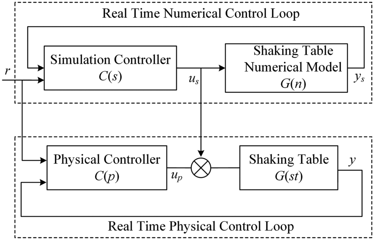
Block diagram of IDCS technique with closed-loop system.
Dynamics of shaking table is evaluated using sine sweep test. In this article, approximation of measured transfer function is carried out using the “fminsearch” command in MATLAB. Equation (10) provides a fourth-order transfer function model G(n). Figure 8 shows that the numerical model can correctly simulate dynamics of the shaking table G(st) from 0 to 15 Hz in the frequency domain

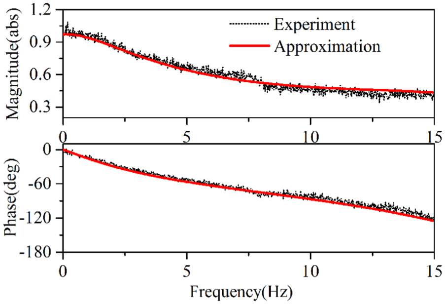
Comparisons of the measured and the approximated transfer function of shaking table.
C(s) corresponds to inverse dynamic model of G(n) in real-time numerical control loop. In real-time physical control loop, physical controller of shaking table C(p) further guarantees stability and robustness. Thus, a good controller is successfully designed to ensure that y tracks r well.
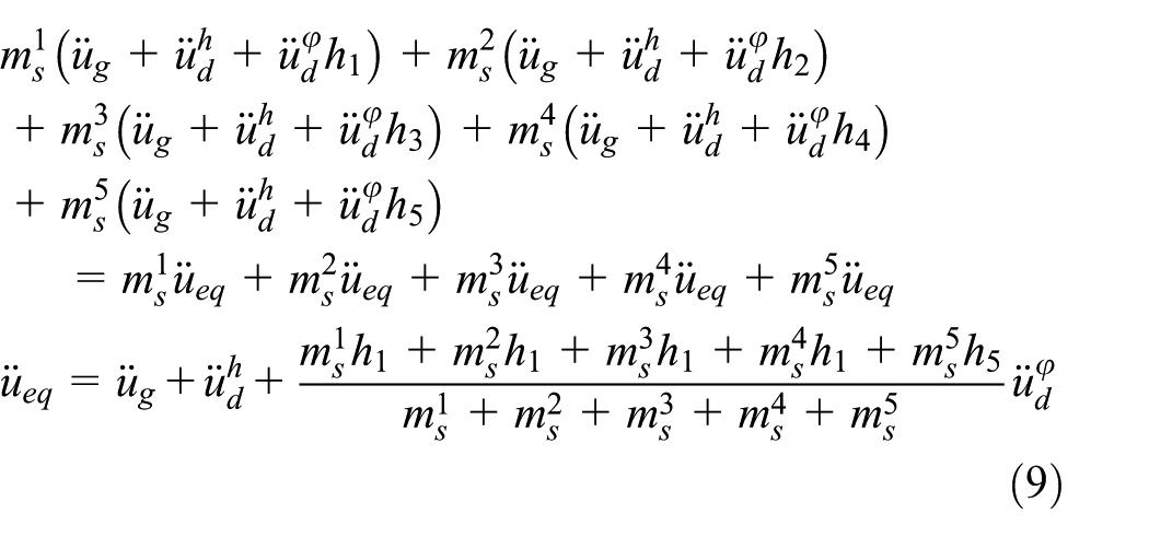
Numerical substructure adopts the state equation in Simulink as solution. Figure 9 shows the calculation module. State variable x consists of modal displacement and modal velocity of soil; input variable u consists of external and coupling loads of soil. Output variable y represents physical acceleration of soil after coordinate transformation. Horizontal and rotational accelerations of rigid foundation are obtained based on the “Selector” module. Equivalent horizontal acceleration is given by equation (9). Real seismic excitation, which is imposed on experimental substructure, is obtained and adopted as driving instruction for the shaking table. Figure 9 presents the matrices A, B, C, and D of the state equation.
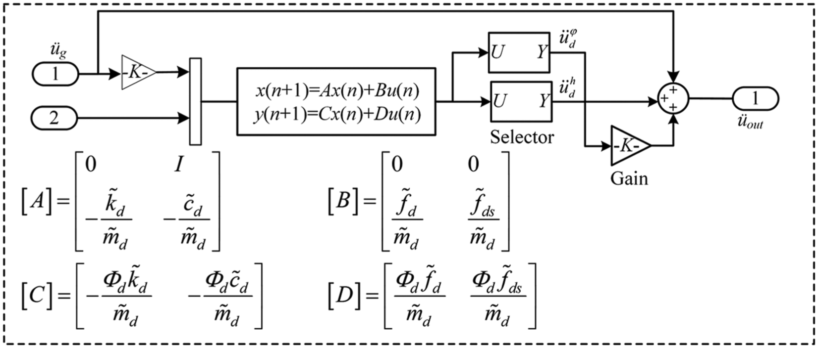
Numerical substructure calculation module.
Experimental analysis
In this article, shaking table real-time substructure experimental platform is used for an equipment–structure–soil interaction system. Earthquake excitation is inputted in accordance with seismic requirements. To prove the reliability of the experimental method, acceleration response of equipment top is adopted as index, and substructure experimental results are compared with those of integrated finite element calculation. Results are also used to evaluate soil influence on seismic responses of the equipment and structure.
Experimental verification
Integrated finite element calculation and analysis are conducted, and calculation results are compared with those of substructure experiment to verify reliability of the proposed method. MATLAB is adopted for calculation of integrated finite elements. 32 Calculation equation is given by equation (5). Computing matrix of numerical substructure is known, whereas calculation matrix of experimental substructure is unknown. A previous section defines the five-DOF calculation model for the equipment–structure system. Calculation matrix of equipment–structure system is obtained based on design parameters and vibration responses. 33 Masses of the first three stories of the structure are also obtained, as represented by m1 = m2 = m3 = 1700 kg; fourth story features a mass of m4 = 1540 kg. The first story presents a stiffness of k1 = 2,423,080 N/m; stiffness of the second, third, and fourth stories measure k2 = k3 = k4 = 3,833,120 N/m. Damping of first story is given by c1 = 4463 N/(m/s), whereas that of the second, third, and fourth stories can be computed as c2 = c3 = c4 = 7061 N/(m/s). Equipment mass is m5 = 90 kg, stiffness is k5 = 93046 N/m, and damping is c5 = 42 N/(m/s). Finally, Newmark-β direct integral algorithm is used to solve the overall motion equation and to obtain desired calculation results.
Figure 10 shows the acceleration responses of equipment top. Responses are obtained by shaking table real-time experiment test and integrated finite element calculations. Compared with integrated finite element calculation results, peak acceleration responses of the equipment in experiments under El Centro, TianJin, and PerSon earthquakes are reduced by 6.0%, 4.5%, and 3.8%, respectively. Acceleration time history curves obtained by the two methods agree with each other along overall trends and meet experimental precision requirements. Results also prove the validity of shaking table real-time substructure experimental method. Errors in the results of the two methods primarily arise from control errors of the shaking table and difference between physical and numerical models of experimental substructures.
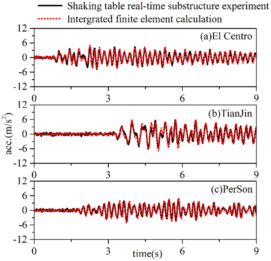
Acceleration responses of the equipment top, as obtained by shaking table real-time experiment test and integrated finite element calculations.
Analysis of experimental results
To evaluate soil influence on seismic responses of equipment and structure, this article conducts a shaking table test on equipment–structure–soil and equipment–structure interaction systems. Earthquake motions are directly inputted into the latter interaction system. Thus, numerical substructure is not included. Figures 11 and 12 show the soil influence on acceleration responses of equipment top and structure top, respectively.
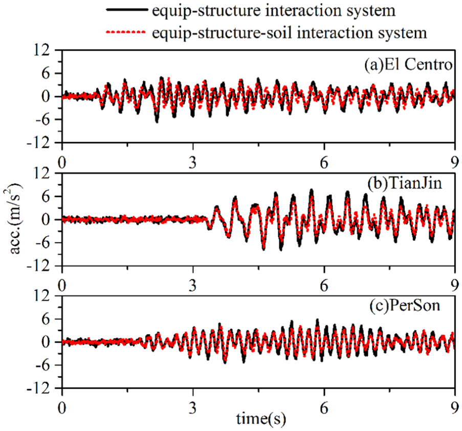
Soil influence on acceleration response of the equipment top.

Soil influence on acceleration response of the structure top.
As shown in Figure 11, acceleration responses of the equipment decreases under soil influence. Under earthquake motions of El Centro, TianJin, and PerSon, peak acceleration responses of the equipment decrease by 9.2%, 18.3%, and 12.0%, respectively. As shown in Figure 12, soil decreases acceleration responses of the structure. Under earthquake motions of El Centro, TianJin, and PerSon, peak acceleration responses of the structure decrease by 15.2%, 23.6%, and 10.1%, respectively. In this experiment, seismic responses of the equipment and structure decrease in general. The decrease can be attributed to energy dissipation, which increases damping of the whole interaction system after intervention of soil.
Based on branch substructure method, this article conducts a shaking table real-time substructure experiment with the equipment–structure system as experimental substructure. The experiment resulted in integrated experimental effects while considering equipment–structure–soil interactions. This experimental method presents the following advantages: first, this method fully utilizes the computing advantages of simulation software to conduct joint experiments; second, introduction of soil numerical substructure model featuring modal reduction guarantees efficient completion of real-time substructure experiment under the prerequisite of guaranteeing computing accuracy. Overall, the method not only meets the requirements of research precision but also promotes experimental research on seismic responses of other interaction systems.
Conclusion
Equipment–structure–soil interactions accurately reflect the actual seismic responses of the equipment and structure. Based on branch substructure method, motion equation is inferred for equipment–structure–soil interaction system, and a shaking table real-time substructure experimental method is proposed for the equipment–structure interaction system. The conclusions can be summarized as follows:
Equipment–structure–soil interaction equation is inferred and transformed based on branch substructure method. Related equation is then applied to shaking table real-time substructure experiment of the equipment–structure–soil interaction system. This experimental method features clear concepts and convenient operations.
Horizontal load equivalence principle is adopted to transform foundation rotational acceleration into equivalent horizontal acceleration, which is imposed on experimental substructure. Through this step, the factor of foundation rotation is considered by horizontal shaking table test, thus increasing accuracy of experimental results.
The real-time numerical feedback control and physical feedback control used for compensating dynamics of shaking table show good performance for controller design.
Results for shaking table real-time substructure experiment are compared with those of integrated finite element calculation. Despite certain errors, results obtained by the two methods show good agreement, proving reliability and effectiveness of the proposed method.
However, the proposed method for equipment–structure–soil interaction systems only considers the influence of linear soil on seismic responses of equipment and structure and cannot obtain comprehensive test data as the experiments of full-coupled systems. Therefore, future researchers should improve the experimental method to other complex interaction systems.
Footnotes
Appendix 1
Academic Editor: Muhammad Akhtar
Declaration of conflicting interests
The author(s) declared no potential conflicts of interest with respect to the research, authorship, and/or publication of this article.
Funding
The author(s) disclosed receipt of the following financial support for the research, authorship, and/or publication of this article: This work was financially supported by the National Science Foundation Project (research project no. 51478312), National Youth Science Foundation Project (research project no. 51208356), and the National Science Foundation Project (research project no. 51278335), China.