
Abstract
In order to study the influence of the impeller eccentricity on the performance of centrifugal pump, the k–ε turbulence model was selected, and ANSYS CFX was provided for numerical simulation calculation of the centrifugal pump with impeller offsets of 0, 1, 3, and 5 mm. The results show that with the impeller eccentricity increasing, the head and efficiency become lower. Under the condition of rated flow, with the impeller eccentricity increasing, the area of low pressure at the suction surface of the short blade inlet become smaller gradually; however, the area of low pressure at the suction surface of the long blade inlet become larger, and the pressure at the impeller inlet and tongue become larger too. The corresponding critical net positive suction head increases in turn, as means that the cavitation performance of the pump becomes worse gradually. The bubble volume fraction in the impeller increases with the decrease of the static pressure at the inlet. The bubble first occurs at the inlet of the blade suction surface, and then extends gradually to the channel and even the outlet. Near the rated flow, radial force on the impeller and volute decreases with the increasing of flow, and the radial force characteristic becomes worse gradually with the increasing of the eccentricity.
Introduction
Pumps are widely used as energy consuming machinery. The low-specific speed centrifugal pumps with high head and low flow rate are widely used in field production, urban water supply, energy and transportation, and many other fields. As the core of the hydraulic components, impeller’s size, shape, processing technology, and so on have decisive impacts on the performance of the pump.1–3 However, in the actual manufacturing process, the quality of asymmetry caused by casting, machining accuracy, assembly errors and the designing of the existence of asymmetric geometry and other reasons lead to the formation of a certain eccentricity, and then causing the hydraulic imbalance of the impeller; these facts would destroy the flow structure, reduce the efficiency, and also would cause vibration, noise, accelerate the bearing wear, reduce the stability and reliability, shorten the service life of the pump, and even cause catastrophic accidents.4–8
For the influence of impeller parameters on centrifugal pump performance, scholars did a series of studies. Tan et al. 9 analyzed the influence of blade wrap angle for centrifugal pump performance. Y Shouqi and colleagues 10 studied the relationship between blade number and centrifugal pump performance. Babayigit et al. 11 researched blade exit angle effect on the multistage centrifugal pump performance. Shukla and Kshirsagar 12 studied in detail about numerical scheme, turbulence model, mesh type and size, and so on to find out the effects of numerical simulation results, and the performance of the centrifugal pump was predicted at the same time.
On the study of centrifugal pump’s internal pressure pulsation and radial force,13,14 Y Zhifeng et al. 15 analyzed the effects of impeller form on pressure fluctuation characteristics based on tests and showed that the blade passing frequency, pump shaft rotation frequency, and lower shaft frequency component exist in the double suction centrifugal pump. Z Lei et al.16,17 numerically studied the influence of different types of impeller and volute tongue and rotor–stator interaction on the performance of centrifugal pump and pressure fluctuation by changing the tongue shape and radial clearance of a centrifugal pump. W Yang 18 analyzed the pressure fluctuation of unsteady flow in a centrifugal pump and showed that the rotor–stator interaction between the impeller and the tongue was the main reason for the pressure fluctuation. Under different flow rate, blade frequency occupied the main position, and the pressure pulsation amplitude at pressure side was greater than that at the suction surface. Majidi 19 studied the unsteady flow field caused by the rotor–stator interaction in the inner of a centrifugal pump using standard k–ε turbulence model, and the unsteady pressure distributions in the flow channel of the impeller and the volute were obtained; the unsteady load distributions on the blade were also calculated. Barrio et al. 20 analyzed the effects of different tongue clearance on pressure in fluctuation and radial force characteristics by controlling impeller and the clearance rate of 23.2%–8.8%.
On the study of centrifugal pump cavitation, L Xianwu et al. 21 calculated three-dimensional cavitation turbulence of the whole flow field for boiler feed water pump with standard k–ε turbulence model and the volume of fluid cavitation model. Five new types of impellers were simulated, and it was found that the blades’ inlet edge extending and the inlet angle adding can obviously improve the cavitation performance of the centrifugal pump. And the flow uniformity was an important factor on improving the cavitation performance. The cavitation performance of a centrifugal pump with its specific speed of 191 was simulated by Y Sunsheng et al. 22 based on computational fluid dynamics (CFD) technology and got distributions of the gas–liquid two phase and temperature. Visser and colleagues 23 studied the cavitation of a high-performance centrifugal pump and found that the centrifugal pump has been improved obviously on the cavitation performance after the transformation of the impeller. Based on the CFD software, the cavitation characteristics of the centrifugal pump were simulated by Kelecy, 24 who predicted the incipient and development of bubbles and revealed the internal flow state inside centrifugal pump preliminarily.
In recent years, many scholars study the impeller effect on energy characteristics of centrifugal pump by changing the geometric parameters of the impeller (such as outlet angle of blades, outlet width of blades, blade number, impeller diameter, etc.) and research the pressure fluctuation characteristics of centrifugal pump by altering the clearance between the impeller and the volute (such as the tongue angle, the base diameter of volute, etc.). Study on the influence of eccentric distance on the internal flow field of centrifugal pump mainly focused on two aspects: one is to do the research by adjusting the relative position of the impeller and the volute, man-made eccentricity, and the other is to study the vortex dynamics problems. However, there are few reports about the influence of symmetric blades on the internal flow field of centrifugal pumps. Therefore, further understanding the influence of unsymmetrical blades on the inner flow field of the centrifugal pump and exploring the relationship between the eccentric distance and energy characteristics of the impeller have important theoretical significance and engineering practical value. The research will provide theoretical data for further research on the vibration and noise of the centrifugal pump.
Model and numerical calculation
Computational models
In this article, the test pump is a single-stage low-specific speed centrifugal pump. The main parameters of the pump are as follows: Q = 15 m3/h, H = 60 m, n = 2900 r/min. The impeller inlet diameter D1 = 45 mm, impeller outlet diameter D2 = 218 mm, impeller outlet width b2 = 5 mm, blade outlet angle β2 = 31°, blade number Z = 4; volute base diameter D3 = 225 mm, volute inlet width b3 = 16 mm, tongue angle φ0 = 22.5°. The whole flow field of three-dimensional shape is modeled by UG9.0, as shown in Figure 1.

Computational domain of the centrifugal pump: (a) computational domain and (b) all domain meshes.
Impeller eccentricity
The impeller eccentricity is set, respectively, into 4 schemes: 0, 1, 3, and 5 mm. The eccentric 5-mm scheme is taken as an example. The realization way of nonsymmetrical blades of the impeller is as follows: first, keeping the geometric parameters of the impeller and the hub location unchanged; second, extending the original blade radius 5 mm along original curvature, then moving center of the impeller 5 mm along radial direction. At last, the nonsymmetrical blades impeller is obtained through cutting the extended leaves based on the new center; the new impeller is shown in Figure 2.

Asymmetric blade design: (a) 0 mm, (b) 5 mm, (c) 1 mm, and (d) 3 mm.
Boundary conditions for numerical computation
Constant calculation
The numerical simulation is completed in the ANSYS CFX software with the standard k–ε turbulence model;25,26 the inlet is set as total pressure, p = 1.013 × 10⁵ Pa, the outlet is set as the mass flow, insulation and no slip boundary for solid wall and standard wall functions for near-wall region. Impeller flow area is set as rotator, the pump chamber and the front and back cover plate of the impeller are set as rotational wall surface, the rotational speed 2900 r/min of impeller, the roughness 0.025 mm, and the convergence precision 1.0 × 10⁻⁵.
Cavitation model
In order to get the results of the model pump cavitation fastly and accurately, the calculation of cavitation model starts with the initial conditions based on the steady flow field results before the cavitation appeared. The Rayleigh–Plesset homogeneous cavitation model was adopted; the inlet is set as total pressure, the outlet is set as the mass flow. The internal cavitation is adjusted through changing the inlet pressure. The medium is clear water of 25°C, the saturated vapor pressure of water is 3574 Pa, and the average bubble diameter is 2 × 10⁻⁶ mm; the reference pressure is set to 0 Pa. The initial bubble volume fraction is set to 0, and the initial water volume fraction is set to 1. The turbulent kinetic energy kin and turbulent energy dissipation rate εin at the inlet are calculated as follows


where uin is the import speed and l = 0.07Dinlet, Dinlet the import diameter.
Unsteady calculation
The three-dimensional non-constant turbulent calculation is based on the results from the constant calculation. The convergence precision is set to 1.0 × 10⁻⁵; the impeller rotating 2 degrees is set as a time step, one time step lasts 0.000113378 s and one cycle is 0.02040816 s. After impeller rotating four cycles, the flow field shows periodicity; the total computation time is 0.16326531 s.
Grid division and independence verification
The meshes for the calculation domain are generated by ANSYS ICEM. In order to obtain fluid linear distribution and grid orthogonality, the hexahedral structured grids with predetermined convergence are used to divide the computational water domain. The meshes have been shown in Figure 1(b).
In order to ensure that the results are not affected by the number of grids, the verification of grid independence is carried out, as shown in Table 1. With the increasing of the number of grids, the external characteristics are tended to be stable. When the total number of grids in the section of the impeller, the volute, and the inlet and outlet are more than 1,600,000, the change of the total number of the grids has little effect on the lift and efficiency, as shown in Figure 3. At this time, the head fluctuation is less than 0.1% of the designed head, which means the calculation results meet the requirements of the grid independence. In the article, the mesh containing 1,574,362 elements is selected as the final mesh in the following calculations; the value of y+ is between 30 and 100.
The test and verify of mesh independence.


Mesh independence test.
Numerical simulation results and analysis
External characteristic analysis
Under the design conditions, the prediction values of the pump head with eccentricity 0, 1, 3, and 5 mm are, respectively, 64.68, 64.26, 64.09, and 63.90 m. Compared to the corresponding designed head H = 60 m, the relative deviations are, respectively, 7.24%, 6.63%, 6.38%, 6.10%. It can been seen from Figure 5(a) that, in the whole ranges of calculation flow rate, the head curves of the four scenarios are relatively close to each other, and the heads of eccentricity 0, 1, 3, 5 mm decline one by one, with the maximum difference of 1.4% between 0 and 5 mm. In Figure 5(b), the efficiency curves of the four scenarios are relatively close to each other, and the efficiency of eccentricity 0, 1, 3, 5 mm decline one by one, with the maximum difference of 1.4% between 0 and 5 mm. Based on Figure 4(a) and (b), the non-eccentric pump has better external characteristics performance than the eccentric one, and pump performance gets worse with the increasing of the eccentricity distance, but the effect of eccentric distance on the performance of the pump is very limited.
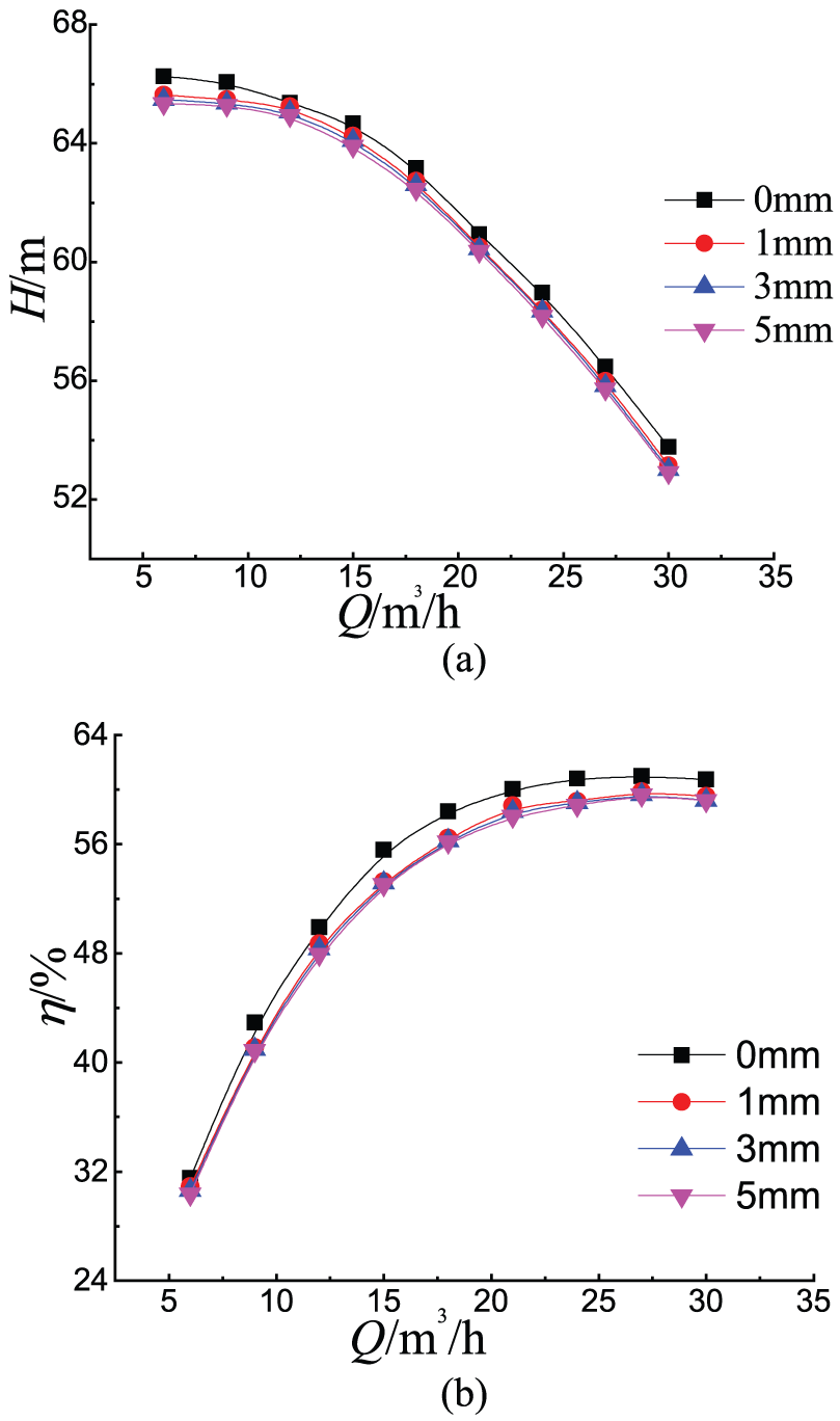
Predict performance curve under four scenarios: (a) curve of flow-head and (b) curve of flow-efficiency.
Characteristics of flow field in centrifugal pump with different impeller eccentricity
The static pressure distributions in the impeller and the volute in the rated condition of the four schemes are shown in Figure 5. The static pressure of the four schemes changes in the middle section of the pump due to slight difference of the blades; however, the variation law is similar. The pressure in the impeller gradually increases from the inlet to the outlet, and the pressure reaches the maximum in the diffusion section of the volute. At the same radius, the static pressure at the pressure surface is significantly greater than that at the suction surface in the impeller. There is a relatively low-pressure region near the blade inlet at the suction surface, which is consistent with the position of the impeller where the cavitation easily happens; this is probably due to part of the fluid separates during entering into the centrifugal pump at this position. In the same flow section, the pressure at the outer wall is higher than that in the volute, and the static pressure tends to increase along the main flow direction, which also proves that the volute is able to convert the kinetic energy of fluid into the pressure energy. With the increase of the eccentric distance, the low-pressure area at the suction side near the inlet of No. 1 blade becomes smaller, the area of No. 3 becomes larger, the No. 2 and No. 4 basically do not change, which are related to the length of the blade.

Static pressure distribution at the rated flow: (a) 0 mm, (b) 1 mm, (c) 3 mm, and (d) 5 mm.
Figure 6 shows the distribution of relative velocity on the middle section of the model pumps in four schemes under the rated flow. At the same radius, the relative velocity increases gradually from the pressure surface of the blade to the suction surface of the adjacent blade, and the velocity distribution within each flow channel in the impeller is similar. These phenomena mean that pressure variance exist between both sides of the blade, which results in the continuous work from blades to the medium. High-speed zone mainly locates inside the passage of the volute, and there is a relatively high-speed zone near the outlet of the impeller right at the tongue. The maximum velocity of the whole flow field is located near the coupling of the impeller and the volute. Due to the impact and the flow separating loss at the tongue, there is a partial low-velocity zone near the tongue too. Overall, the relative velocity distributions of the four schemes are similar. As eccentric distance increases, the low-velocity zone at the impeller inlet and the tongue has an increase trend, and the low-velocity zone of the 5-mm scheme presents the obvious non-symmetry in the impeller inlet.

Relative velocity distribution at the rated flow: (a) 0 mm, (b) 1 mm, (c) 3 mm, and (d) 5 mm.
The turbulent kinetic energy indicates the extent of turbulent fluctuation, and the size and distribution show the size and area of pulse diffusion and viscous dissipation. Figure 7 shows the distribution of turbulent kinetic energy at the middle section for the four schemes under rated conditions. The flow inside the impeller is steady, and the turbulent kinetic energy is small along the blade profile, while it is large at the local region of the volute exit. It is because the large velocity fluid at the volute exit impacts the low-velocity fluid in the outlet pipe; the flows at the local region of the volute exit become disorder. And the turbulent kinetic energy is the maximum near the tongue; it is caused by interference between the tongue and the impeller, large impact and backflow emerge near the tongue. And the intensity and area of the turbulent kinetic energy enlarge when the eccentric distance increases.

Turbulence kinetic energy distribution at design point: (a) 0 mm, (b) 1 mm, (c) 3 mm, and (d) 5 mm.
Cavitation characteristic analysis
If absolute pressure of the fluid drops to vaporization pressure, the medium begins to vaporize and forms bubbles. As the liquid flows to a high-pressure position, the high-pressure liquid around will cause the bubble to shrink and explode. At the same time, the surrounding liquid fills holes at high speed, collides with each other, and may form a water hammer.
Cavitation characteristic curve
The effective LNPSHa is the surplus energy more than the vaporization pressure in unit weight of the liquid at the pump inlet, provided by the suction device. The definition is

With the reduction of the effective LNPSHa, the pump’s head changes slowly, and the head shows a sudden drop after a critical point. The corresponding effective LNPSHa is the critical cavitation NPSHa (available net positive suction head) of the centrifugal pump when the head drops down by 3%. Under the rated flow, the critical cavitation NPSHa of the four schemes are 2.24, 2.28, 2.36, 2.45 m, respectively. Therefore, the 0-mm eccentric scheme has the best cavitation performance, and the cavitation performance changes with the increase of eccentricity distance. As shown in Figure 8, the larger flow rate is, the higher effective LNPSHa is.

Cavitation performance at different conditions for 0-mm eccentricity.
Void distribution in the impeller
The critical cavitation NPSHa of eccentric 0-mm scheme at 0.8Q, 1.0Q, 1.2Q is 1.91, 2.24, 2.51 m, respectively. Figure 9 shows the bubble volume fraction distribution in the impeller under different conditions. When LNPSHa = 2.24 m, the cavitation in the pump is the most serious at 1.2Q, while it is light at 0.8Q. This is consistent with the theoretical analysis; the cavitation performances of pumps become worse with the increase of the flow rate.

Bubble volume fraction distribution at different conditions for 0-mm eccentricity: (a) 0.8Q, (b) 1.0Q, and (c) 1.2Q.
As shown in Figure 10, the bubble volume fraction in the impeller increases with the decrease of the inlet pressure among four schemes. Cavitation first appears at the suction surface of the blade, and then gradually spreads to the impeller flow channel and even to the impeller outlet. When the inlet pressure reduces to a certain degree, the flow channel of the impeller is almost completely blocked by the cavity. When the LNPSHa is 2.24, 2.28, 2.36, 2.45 m, the four schemes reach the critical cavitation state, and bubble distributions at this time are almost the same. When the LNPSHa are 3.05 and 2.17 m, the bubble distribution of four schemes increases in turn due to different flow fields caused by the asymmetry blades.

Bubble volume fraction distribution of four schemes at design point: (a) eccentricity: 0 mm, (b) eccentricity: 1 mm, (c) eccentricity: 3 mm, and (d) eccentricity: 5 mm.
Pressure fluctuation characteristics
Determination of monitoring points
To study the distribution law of pressure fluctuation in low-specific speed centrifugal pump and the influence of unsymmetrical impeller, pressure fluctuation monitoring points are arranged at some important positions in the middle section of the impeller and the volute, as shown in Figure 11. P1 and P2 are set to monitor pressure fluctuation along the circumferential direction in the flow channel of the volute, and P3 is set to monitor the pressure fluctuation of the diffuser section of the volute. P4 is set to monitor the pressure fluctuation at the outlet of the volute.
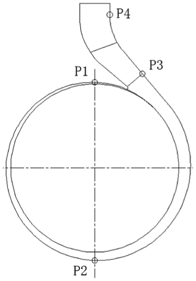
Location of monitoring points.
Frequency domain of eccentric 0-mm pressure fluctuation under different working conditions
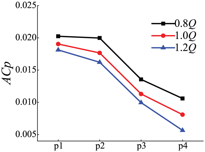
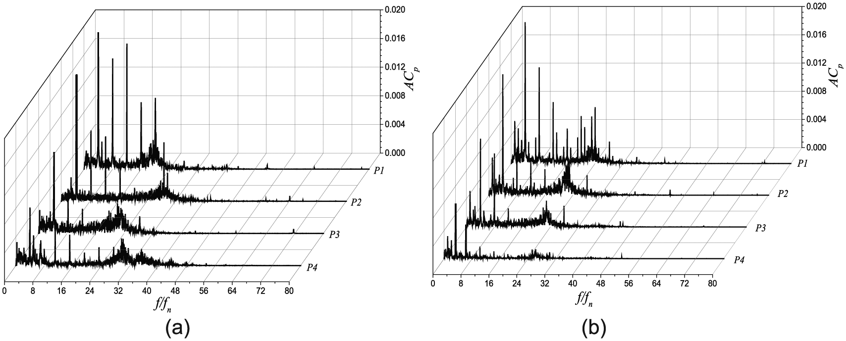
Study the pressure fluctuation of various monitoring points in the 0.8Q, 1.0Q, and 1.2Q conditions for the eccentricity 0-mm scheme. As shown in Figure 12, in the 0.8Q and 1.0Q conditions, the main frequency of P1 is three times of the blade passing frequency, and the main frequency of P1 at 1.2Q is two times of the blade passing frequency. These phenomena also show that the liquid flow near the tongue at P1 is extremely unstable; the pressure fluctuation frequency at P1 has a tendency to the low-frequency region with the increasing of the flow rate. Frequency characteristics at P2, P3, and P4 under other different flow rates are consistent with the design flow rate. It shows in Figure 13 that the pressure fluctuation amplitudes at the monitoring points under different operating conditions gradually decrease along the volute. The pressure fluctuation amplitude at the same monitoring point decreases with the increasing of the flow rate. The minimum pressure fluctuation amplitude of four monitoring points is under the condition of 1.2Q; this may be due to the decline of the head under the condition of large flow rate and the reduction of backflow at the seal ring, and the disturbance of the flow field at the inlet of the impeller reduces.
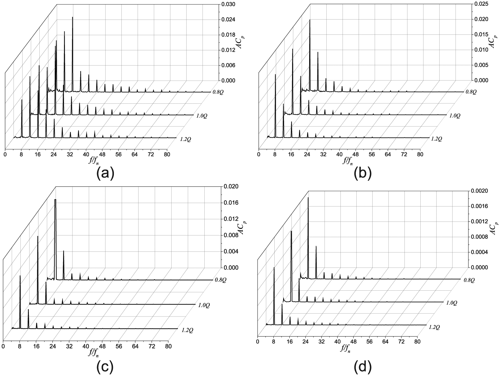
Frequency domain of monitoring points in volute under different flow rates: (a) P1, (b) P2, (c) P3, and (d) P4.

Pressure pulsation amplitude comparison of monitoring points in volute.
Time domain and frequency domain analyses of pressure fluctuation at design flow rate
Pressure fluctuation frequency domains of four schemes at four monitoring points under design flow rate are shown in Figure 14. Similar with the eccentric 0-mm scheme, the main frequency and the second dominant frequency of the other three schemes at P1 are three times and one time of the blade passing frequency, respectively. While the main frequency and the second dominant frequency of the other three schemes at P2, P3, and P4 are one time and two times of the blade passing frequency respectively. This shows that the interference between the impeller and the volute as the pulsating source influences on the flow field. Compared to the eccentric 0-mm scheme, the shaft frequency and its harmonic frequencies for the eccentric 1-, 3-, and 5-mm schemes have obvious amplitudes, and the frequency components of pressure fluctuation are very complex.
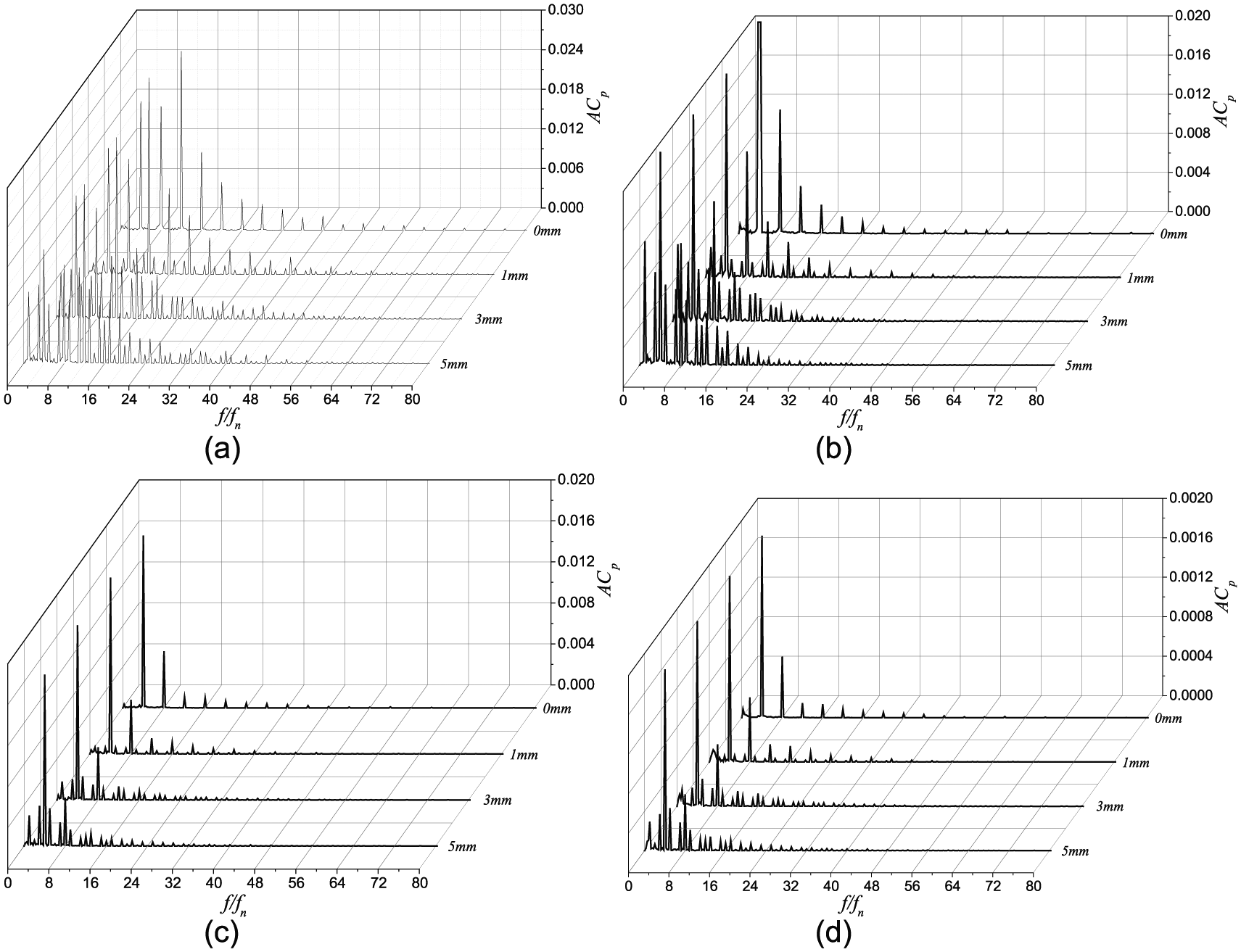
Frequency domain of four schemes in volute at design flow rate: (a) P1, (b) P2, (c) P3, and (d) P4.
Further analysis shows that the amplitude of blade passing frequency and its harmonic frequencies of 0-, 1-, 3-, and 5-mm eccentricity are basically the same size. The amplitude of the shaft frequency and its harmonic frequency (besides the blade passing frequency and its harmonic frequencies) increases in turn. That means, the pressure pulsation characteristics become worse with the increase of the eccentric distance, as shown in Figure 15. This may be due to four different lengths of asymmetrical blades. The interference effect between blades and the volute is not regular, leading the flow field unstable and the frequency composition complicated, and the pressure fluctuation characteristic becomes worse.

Pressure pulsation amplitude comparison of four schemes in volute at design flow rate: (a) one-time blade passing frequency and (b) one-time axis frequency.
Radial force analyses
Radial force of the eccentric 0-mm scheme
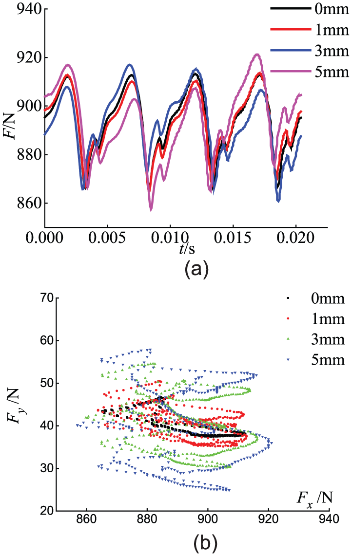
The time domain and vector diagram of the radial force on the impeller of the eccentric 0-mm scheme under different flow rates are shown in Figure 16, and the radial force acting on the impeller is periodic. Under the 0.8Q condition, the radial force is the largest, and the force of 1.2Q is the smallest. It is because of adopting the method of enlarging flow rate to design the impeller. The best operating point is not the design flow rate but the large flow rate. As shown in Figure 16(b), the vector coordinates of any point in the graph represents the magnitude and direction of the radial force at a certain time. In one cycle, the radial force on the impeller is changed in the magnitude and direction, and the distribution is symmetrical about the axis.

Time domain and vector diagram of radial forces in impeller under different conditions: (a) time domain and (b) vector diagram.
The time domain and vector diagrams of the radial force on the volute of the eccentric 0-mm scheme under different flow rates are shown in Figure 17, and the radial force acting on the volute is periodic and consistent with the change rule of that acting on the impeller. It shows that the radial force is related to the interference of the impeller and the volute. The radial force on the volute decreases with the increase of the flow rate, which also reflects that the best working condition is under large flow rate. Under the same condition, the radial force on the impeller is much smaller than that on the volute, which is mainly due to asymmetric structure of the volute, leading to the uneven distribution of velocity and pressure on the cross section and resulting in large radial force. As can be seen from Figure 17(b), in a rotating cycle, the radial force on the volute under different flow rates changes, and its distribution is mainly in the first quadrant.

Time domain and vector diagram of radial forces in volute: (a) time domain and (b) vector.
Radial force analysis of four schemes under design flow rate
The time domain and vector diagrams of the radial force on the impeller for the four schemes under the design flow rates are shown in Figure 18. The radial force of the eccentric 0-mm scheme is periodic, and the radial force fluctuation amplitude shows sharp and irregular when the impeller with the 1-, 3-, 5-mm eccentricity. That means the radial force characteristics become worse with the increase of the eccentricity distance. It is mainly due to the asymmetry of the structure, leading to uneven distributions of velocity and pressure around and in the impeller. As shown in Figure 18(b), in a cycle, the radial force on the impeller changes, and its distribution is around the axis of y = x.

Time domain and vector diagram of radial force on impeller of four schemes: (a) time domain and (b) vector diagram.
Figure 19 is the time domain and vector diagram of the radial force on the volute for the four schemes under the design flow rates. The radial force on the volute has obvious periodicity. There is a little difference between the amplitudes of the waves, and the difference increases with the increasing of the eccentricity distance. This also accounts that the eccentric radial force characteristics become worse. In Figure 19(b), during a rotation period, the magnitude and direction of the radial force on the volute change in different working conditions. The greater the eccentric distance is, the more dispersed the radial force distribution is, and the distribution is in the first quadrant.
Time domain and vector of radial forces on volute of four schemes: (a) time domain and (b) vector.
Experimental studies
External characteristic test
This experiment was conducted in the open experimental platform of national pump and system research center, and the equipment is shown in Figure 20(a). The original models with the 0- and 3-mm eccentric impeller had been experimented, respectively. The impellers are shown in Figure 20(b) and (c).

Experiment facilities and impellers: (a) experiment device, (b) eccentric 0-mm impeller, and (c) eccentric 3-mm impeller.
The predicted and the tested head, as well as efficiency, have been compared in Figure 21 for the eccentric 0- and 3-mm impeller. In general, the predicted performance of the two schemes is basically in agreement with the test results. The predicted heads and efficiencies are all larger than the test. The errors of the head at the design flow rate between prediction and test values are 7.54% and 5.52%, respectively, when the eccentricity is 0 and 3 mm, and the errors of the efficiency are 2.73% and 2.32%, respectively. The simulation results are in agreement with the experimental results.
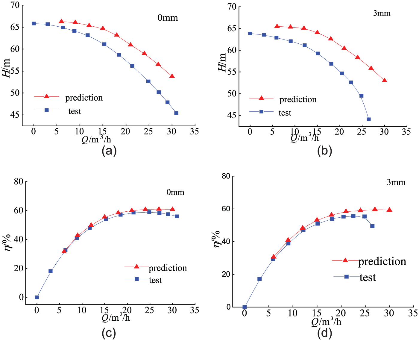
Comparison of prediction and experimental performances: (a) 0 mm, (b) 3 mm, (c) 0 mm, and (d) 3 mm.
Cavitation performance test
When the centrifugal pump cavitation test is carried out, under the condition of keeping constant flow, the pump inlet pressure is reduced to adjust LNPSHa gradually. The critical LNPSHc is chosen when the pump head decreases by 3%, which can effectively reflect the anti-cavitation performance of the pump.
The prediction and experimental curves of cavitation performance for 0- and 3-mm schemes under 0.8Q, 1.0Q, and 1.2Q are shown in Figure 22. It can be found that although the simulation results and the test results have a small amount of deviation, the simulation curve is still a good prediction of the head with the change of LNPSHa. At first, the head did not change significantly with the decrease of LNPSHa; when LNPSHa reduces to a certain value, the pump head appears steep drop. During the early cavitation forming, a small amount of vacuoles have no significant effect on the inner flow field; with the further development of cavitation, when LNPSHa decreases to the critical value LNPSHc, bubbles may block impeller, and the head decreases sharply.
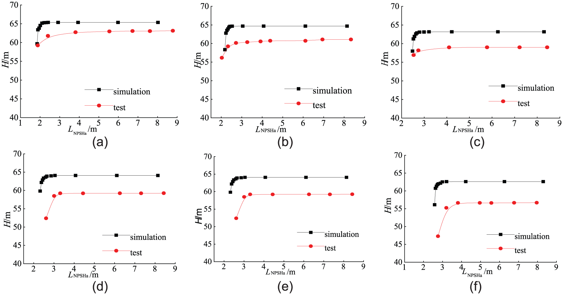
Comparison of cavitation performance between simulation and the test: (a) eccentric 0 mm (Q = 12 m3/h), (b) eccentric 0 mm (Q = 15 m3/h), (c) eccentric 0 mm (Q = 18 m3/h), (d) eccentric 3 mm (Q = 12 m3/h), (e) eccentric 3 mm (Q = 15 m3/h), and (f) eccentric 3 mm (Q = 18 m3/h).
At the same flow rate, the critical value LNPSHc of the eccentric 0-mm scheme is less than that of the eccentric 3-mm scheme. This means that the cavitation performance becomes worse with the increase of eccentric distance. The simulation value is slightly less than the experimental value, and the absolute error is 0.4 m between the test and the experimental value, and the maximum relative deviation is 15.7%.
Experimental study of pressure fluctuation
In order to monitor the circumferential pressure fluctuation characteristics in the volute, four measuring points were arranged in the circumferential position of the inner wall of the volute. The positions of these points are the same as P1, P2, P3, and P4; the high-frequency pressure sensor and testing instrument are shown in Figure 23.

Pressure fluctuation experiment facilities: (a) high-frequency pressure sensor and (b) HSJ-2010 hydraulic mechanical comprehensive testing instrument.
Figures 24 and 25 list the frequency domain of the pressure fluctuation and maximum amplitude of the eccentric 0-mm scheme at different flow rate. The main frequency of the four monitoring points in the volute is four times of the axis frequency, and the results are consistent with the simulation results (except for the monitoring point P1). It also shows that the blade passing frequency is the main frequency component of the pressure pulsation in the volute. The pressure fluctuation amplitudes of the four monitoring points at three different flow rates change almost consistently. The amplitudes of pressure fluctuation along the flow direction in the volute gradually reduce, and the pressure fluctuation amplitude at the same monitoring point decreases with the increase of the flow rate. There is a certain deviation between the experimental values with the simulation values, on the one hand, maybe due to the four pressure measuring holes on the wall of the volute which have a certain effect on the internal flow, on the other hand, the experimental points are not exactly at the same position of the simulation points.
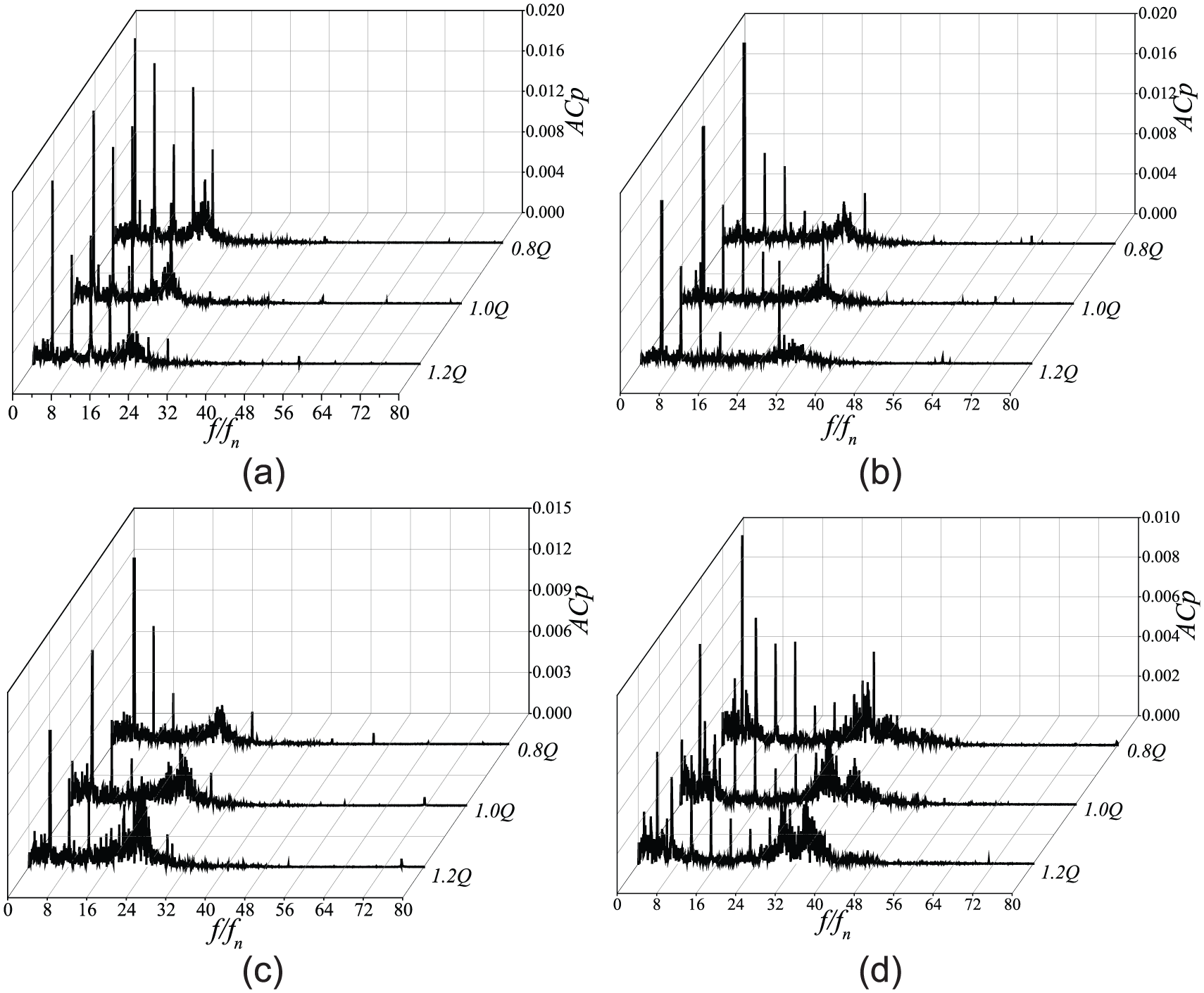
Frequency domain of monitoring points in volute under different conditions: (a) P1, (b) P2, (c) P3, and (d) P4.
Pressure pulsation amplitude of monitoring points in volute.
Figures 26 and 27 list the comparison of frequency domain of pressure fluctuation and maximum amplitude at four monitoring points for the two schemes at the design flow rate. It can be found that, consistent with the eccentric 0-mm scheme, the main frequency of pressure fluctuation at four monitoring points of eccentric 3-mm scheme is one time of the blade passing frequency. For the same monitoring point, the main frequency amplitude of the two schemes is basically consistent. But, the eccentric 3-mm scheme has significant amplitude at one time of the axis frequency. It is consistent with the simulation results. At the same time, it also shows that the pressure fluctuation characteristic of the model pump becomes worse with the eccentric.
Frequency domain of two schemes in volute: (a) 0 mm and (b) 3 mm.

Pressure pulsation amplitude comparison of four schemes in volute.
Conclusion
With the increase of the eccentric distance for the impeller, the head and efficiency of the pump becomes smaller, but the influence of eccentric distance on the head and efficiency is limited.
At the design flow rate, with the increase of the impeller eccentric distance, the low-pressure area at the suction side of the short blade inlet gradually becomes smaller and that at the suction side of the long blade inlet becomes larger; the low-speed area near the impeller inlet and the tongue has increased.
Under the same flow rate, the cavitation performance of the centrifugal pump becomes worse with the increase of the eccentric distance. Cavitation first appears at the suction side of the blades. As the inlet pressure of the pump gradually decreases, the cavity gradually spreads to the center of the impeller channel.
The main frequency of the four schemes at the monitoring point P1 is three times of the axis frequency, and the main frequency of the P2, P3, P4 is the blade frequency. Compared to the eccentric 0-mm scheme, with the increasing of the eccentric distance of the impeller, the frequency component of the pressure pulsation is more complex.
Under different flow rates, the radial force on the impeller and the volute in the eccentric 0-mm scheme shows obvious periodicity. The radial force on the impeller and the volute gradually gets worse with the increase of the eccentricity distance of the impeller.
Footnotes
Academic Editor: Roslinda Nazar
Declaration of conflicting interests
The author(s) declared no potential conflicts of interest with respect to the research, authorship, and/or publication of this article.
Funding
The author(s) disclosed receipt of the following financial support for the research, authorship, and/or publication of this article: The paper is supported by the Natural Science Funds of Jiangsu Province (BK20131256).