
Abstract
The complex three-dimensional turbulent flow field in a centrifugal water pump with three asymmetrical diffusers was numerically simulated. The characteristics of pressure and force fluctuations inside the model pump were investigated. Fast Fourier transformation was performed to obtain the spectra of pressure and force fluctuations. It indicates that the dominant frequency of pressure fluctuations is the blade passing frequency in all the sub-domains inside the pump and the first blade passing frequency energy (first order of blade passing frequency) is the most significant. The dominant frequency of pressure fluctuations at the location of diffuser outlet is featured by low frequency (less than 1 Hz), which may be due to the locally generated eddy structures. Besides, the dominant frequency force fluctuations on the impeller blades are also the blade passing frequency. The existence of the three asymmetrical diffusers has damping effect on the pressure fluctuation amplitude and energy amplitude of pressure fluctuations in the diffuser domain dramatically, which indicates that the diffusers can effectively control the hydraulically excited vibration in the pump. Besides, the prediction of the dominant frequency of pressure fluctuations inside the pump can help to utilize the pump effectively and to extend the pump life. The main findings of this work can provide prediction of the pump performance and information for further optimal design of centrifugal pumps as well.
Introduction
The centrifugal water pumps, a kind of widely used fluid machinery, play an important role in almost all industrial and agricultural fields. The flow inside a centrifugal pump is three-dimensional (3D) involving secondary flows and even complex vortical flow structures due to the complexity and asymmetry of the volute flow passage configuration. The turbulent flow will lead to vibration of the overall pump unit and alternating stresses of the impeller blades under design condition and even stronger under off-design conditions, which is considered as flow-induced instability. Not only the impeller but also the other components of the unit may suffer from serious damage due to flow-induced vibrations.
Rotor–stator interaction plays an important role in the investigation of the unsteady flow inside the water pump. Dring et al. 1 pointed out that the mechanism of rotor–stator interaction inside the axial turbine can be classified into two categories: potential flow effect transmitted to upstream and downstream and wake effect in the downstream. Potential flow effect, taking no account of viscous effect, is only influenced by the relative motion between rotor and stator. The transmission of potential flow effect dissipates fast, and its effect is obvious only when the space between the blades is small enough. On the other hand, wake effect takes the viscous effect into account, which is produced when the blades in the downstream are impacted by the flow. 2 The periodic effect of wake flow can lead to complicated unsteady flow field and consequently affects the flow downstream. 3 For centrifugal pump with diffusers, the mechanism of rotor–stator interaction is as follows. The twisted blade and wake effect can influence the flow field in the diffusers; meanwhile, the diffusers can also influence the flow field upstream in the rotor. The small space between rotor and diffusers leads to more turbulent flow inside the pump.4–6
Research of flow-induced vibration and alternating forces inside centrifugal pumps has been a key research topic because of the increasing requirements of high reliability, low vibration, and low noise for the pumps. Many investigations have been carried out to study the physical phenomena and mechanisms involved in such complex flow field. The development of modern experimental techniques for fluid dynamics, such as particle image velocimetry and laser Doppler velocimetry, makes it possible to measure the complex flow field inside pumps.7,8 Khalifa et al.
9
demonstrated that the measured pressure fluctuations in the discharge pipe were different from that inside the pump. Pump vibration was related to the internal pressure fluctuations, and the pressure fluctuation in the clearance between the impeller and volute tongues was the major influencing factor contributing to the violent vibration. However, the flow field inside a centrifugal water pump is extremely difficult to be measured by means of experimental techniques due to rotor–stator interaction, which inevitably calls for reliable numerical simulations using computational fluid dynamics (CFD) techniques. Croba and Kueny
10
calculated a two-dimensional (2D) centrifugal pump and analyzed the unsteady and instantaneous flow field. Researchers carrying out CFD calculations usually pay main attentions to the flow (velocity and pressure fields) characteristics. Spence and Amaral-Teixeira
11
investigated the behaviors of pressure fluctuations in a centrifugal pump. It was found that amplitudes of pressure fluctuations were strong at the impeller outlet through measuring the fluctuation levels at various positions. Stickland and Scanlon
12
used sliding mesh technique to take into account the impeller–volute interaction, which made the simulation of flow and pressure fluctuations more accurate. Solis et al.
13
performed numerical simulations on a volute-type centrifugal pump. They studied the characteristics of pressure fluctuation levels at the blade passage frequency (BPF;
As introduced above, numerical simulation approaches can be used to predict the complicated flow field inside a centrifugal water pump and play a guiding role in optimizing structure of centrifugal pumps and improving the hydraulic performance as well. Hence, CFD numerical simulation method has been employed in our previous studies on the complex flow characteristics in different water pumps.19,20 In this study, numerical simulations are performed to investigate the characteristics of unsteady flow and pressure fluctuations in a centrifugal water pump with asymmetrical diffusers. Furthermore, the force fluctuation characteristics of the impeller blades are investigated. Such information is of great importance in further optimal design of the centrifugal water pumps, which is the motivation of this study.
Numerical simulation procedures
Computational domain and mesh system
The simulated object is a single-stage centrifugal water pump with four impeller blades and three asymmetrical space-diffuser vanes. The 3D perspective of the model pump is illustrated in Figure 1. The inlet diameter is 226 mm and the maximum diameter of the rotor is 265 mm. The computational domain covers the entire hydraulic passage of the model centrifugal pump in order to capture the whole flow field and to detect any possible asymmetrical structures in the flow. Appropriate extensions are processed at the inlet and outlet to minimize the effects of boundary conditions and ensure numerical stability. The extended lengths of inlet and outlet pipes are 5 times of impeller inlet hydraulic diameter and 10 times of diffuser outlet hydraulic diameter, respectively. The computational domain is divided into four zones including inlet pipe, impeller, diffuser, and outlet pipe.

(a) 3D perspective of model pump and (b) an enlarged overview of the impeller and the diffuser passage.
Considering the configurational complexity, the mesh generated in diffuser domain is unstructured, and structured mesh systems are used for other parts. The mesh near the boundary is refined, as shown in Figure 2. In order to finalize a proper mesh system for the present numerical simulations, a grid independence analysis is at first performed. Steady-flow regime is chosen for this purpose and the monitoring target is selected as the total water head. The result of grid independence analysis is shown in Figure 3. It can be seen that when the mesh number is larger than

Sketch of the generated mesh system.

Simulated total water head at different numbers of grid nodes (note that the measured value of H in experiment was 3.60 m).
Governing equations and turbulence model
The governing equations for an incompressible fluid flow are solved for the flow field inside the centrifugal pump. The basic equations in a manner of Reynolds-averaged Navier–Stokes (RANS) are the following continuity and momentum equations, respectively

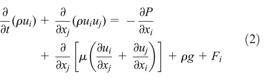
where
In this numerical study, the shear stress transport (SST)
Boundary conditions and numerical methods
The commercial CFD code, ANSYS CFX, was employed to solve the governing equations of flow in the model centrifugal water pump. The boundary conditions are defined as follows. At the inlet, volume flow rate
Discretizations of continuity and momentum equations are conducted by means of the finite volume method in the space region. Advection scheme is set to be in high-resolution option. Turbulence numeric is the first order. The convergence criterion of
Results and discussions
Flow field analysis under steady state
Figure 4 is an overview of the numerically captured streamlines inside the centrifugal pump. It can be seen that the flow in the inlet pipe to impeller is smooth, which proves the necessity of an extension of the inlet pipe. When the liquid flows to the impeller, it begins to rotate with the blade and the magnitude of the velocity increases. In the diffuser part, the flow velocity begins to decrease accompanied with swirling in the flow direction. The condition of rotating sustains to the extended component of pump. In addition, there are low-speed vortices at the region of the tongue.
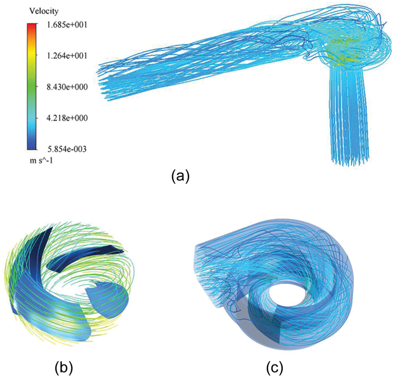
Streamline distributions inside the (a) model pump, (b) impeller (enlarged view), and (c) diffuser (enlarged view).
The kinetic energy of flow in the impeller is converted into pressure by applying the angular momentum to the constant mass flow of liquid going through the impeller passage. The increase in pressure in the rotor passage is clear in the overview of the pressure field inside the pump as shown in Figure 5, which describes the energetic transformation happening in the flow passage.

Pressure distributions in the (a) pump and (b) diffuser (enlarged view).
The pressure distribution on the impeller blades is extracted and illustrated in Figure 6. It can be seen that the pressure level on blades gradually increases from leading edge to trailing edge and presents a belt-shaped distribution. It is noteworthy that at the leading edge, the local pressure is especially high as a result of the impact of water.

Pressure distributions on impeller blades.
From the results shown above, we can see that the performed numerical simulation can accurately predict the total water head of the model pump with a deviation of about 2% compared with the experimental result (Figure 3); meanwhile, the behaviors in the flow field under steady state inside the centrifugal pump are all reasonable, which demonstrates that the numerical procedure in our study is reliable. In the following parts, the transient pressure and force fluctuations can then be analyzed.
Analysis of the characteristics of pressure fluctuations on time domain
In order to determine the transient variation and intensity of pressure fluctuations, a time-dependent non-dimensional pressure coefficient (

Schematics showing the monitoring points located in different regions.

Schematics showing the monitoring points located at the impeller (a) inlet and (b) outlet.
The calculated pressure coefficient

Pressure fluctuation transitions at impeller inlet.

Pressure fluctuation transitions at impeller outlet.
Monitoring points located in the diffuser domain.

Pressure fluctuation transitions monitored in the diffuser region at (a) points P7–P9, (b) points P10–P12, and (c) points P13–P15.
Pressure fluctuation transitions at monitoring points in the volute region.

Monitoring points located at the diffuser outlet.

Pressure fluctuation transition at volute outlet.
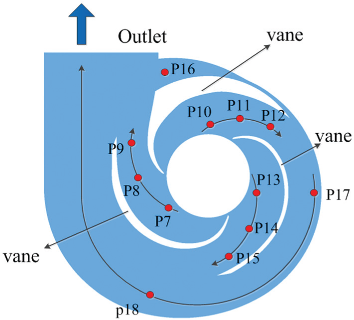
Because the diffuser has three asymmetrical space-diffuser vanes, the flow is divided into three parts from impeller outlet. In order to analyze the respective characteristics in these three different flow passages, three monitoring points are set in every vane passage. Monitoring points P7–P18 located at diffuser domain are set at the middle cross section of volute, and the detailed positions are shown in Figure 11. The viewing direction is from the impeller inlet. Figure 12 shows the time domain of pressure fluctuations at points P7–P15. For convenience in the following discussions, we denominate the passage with points P7–P9 as “Passage 1,” the passage with points P10–P12 as “Passage 2,” and the passage with points P13–P15 as “Passage 3,” respectively. It can be seen that in each flow passage, the largest PFA occurs at diffuser inlet, and along with the flow direction, the pressure fluctuation becomes weakened gradually. In Passage 1, the PFA is significantly larger at point P7 than at points P8 and P9. Note that the points P8 and P9 are located near the outlet of the diffuser, and so the flow is more stable in this region. The PFAs at points P11 and P12 are larger than at points P8, P9, P14, and P15. In consideration of the positions of these monitoring points, points P11 and P12 are nearer to the volute boundary, indicating that the pressure fluctuation is stronger in the region near the boundary.
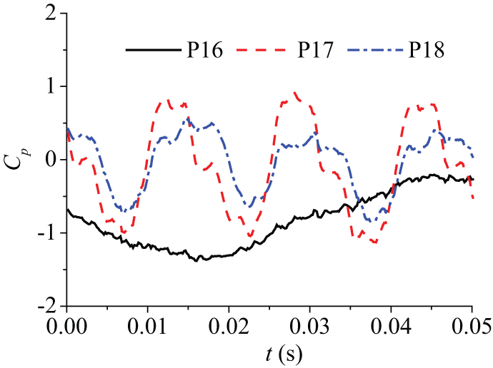
The pressure fluctuations at monitoring points P16–P18 are shown in Figure 13. The PFAs gradually reduce along with the flow direction. The pressure fluctuation at point P16, which is located at tongue, is different from those at other monitoring points: the period of the pressure fluctuation is much longer than other points in diffuser domain because of the existence of vortices having low velocity in this region (as discussed in the following section).
The distribution of monitoring points P19–P21 at the diffuser outlet is shown in Figure 14 schematically. The pressure fluctuations at these locations are demonstrated in Figure 15. We can see that the pressure fluctuation is more stable in this region; among the three monitoring points, the amplitude of P19 located at the center of the passage is the largest.
In the rotating part, the main influencing factor on flow field and consequently flow-induced vibration to the solid structures is the rotor–stator interaction; while in the static part, the influence from the existence of vortex structures will become obvious. In Figure 16, the vortex structures were extracted by means of the so-called Q-criterion.22,23 Here,

Vortex structures extracted in the passage of diffuser: (a) the passage of diffuser and (b) partial enlarged drawing of volute tongue.
Spectrum analysis of pressure fluctuations
The BPF of the presently simulated model pump is calculated by 16.3 Hz (rotation frequency) multiplying by 4 (blade number), which is 65.2 Hz. The spectrum of pressure fluctuations as a function of frequency at each monitoring point is calculated using fast Fourier transformation. Figures 17–21 show the spectra of pressure fluctuations at monitoring points P1–P21 (as designated in Figures 8, 11, and 14). In each figure, the x-coordinate is the relative frequency normalized with the rotation frequency of
The energy distributions in pressure fluctuations at impeller inlet are shown in Figure 17. It can be seen that at impeller inlet, the energy amplitudes of pressure fluctuations at the three monitoring points show the following behavior: the largest at point P2, the smallest at point P3 near the shroud, and in the middle at point P1 near the hub; the pronounced frequency of the pressure fluctuation and its harmonic are four times the BPF and its harmonics, respectively, due to the rotation of the four impeller blades.

Spectra of pressure fluctuations at locations of impeller inlet.
Spectra of pressure fluctuations at locations of impeller outlet.

Spectra of pressure fluctuations at different passages of diffuse domain at (a) points P7–P9, (b) points P10–P12, and (c) points P13–P15.

Spectra of pressure fluctuations at locations of volute region.

Spectra of pressure fluctuations at locations of diffuser outlet.
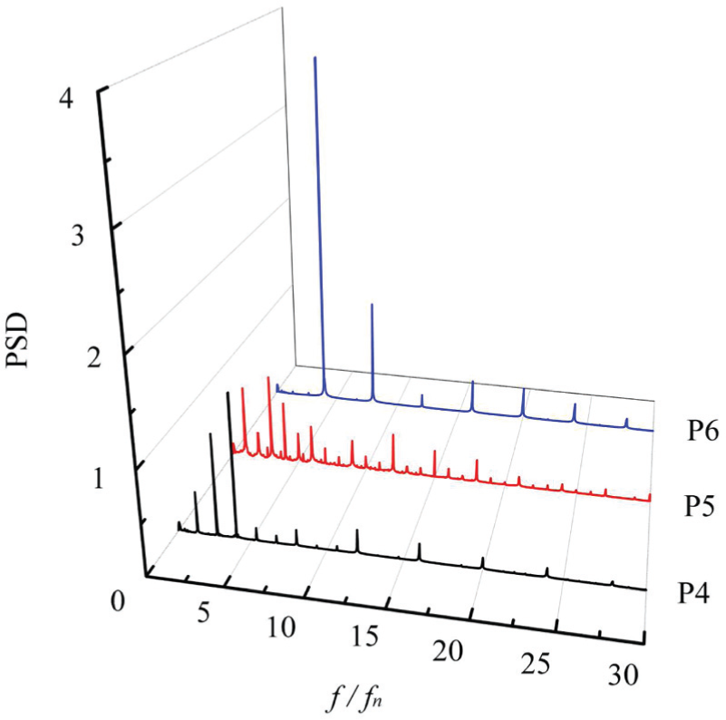
The spectra of pressure fluctuations at impeller outlet are plotted in Figure 18. It is found that at impeller outlet, the energy amplitude of pressure fluctuations is different from that at the impeller inlet: overall, larger in the former than that in the latter. This phenomenon is caused by the rotor–stator interactions. Other different behaviors of the energy amplitudes of pressure fluctuations at the three monitoring points at impeller outlet are as follows: the largest at point P6 near the shroud, the smallest at point P5, and in the middle at point P4 near the hub. Furthermore, although the dominant frequency is still the impeller BPF, the energy distribution at low frequency becomes pronounced at impeller outlet as compared with that at impeller inlet, which should be due to the vortex rotating and vortex shedding behaviors in the diffuser.
The energy distributions in pressure fluctuations at different flow passages of diffuser domain are shown in Figure 19. It can be seen that near the diffuser inlet, the energy amplitude of pressure fluctuations becomes the largest, and it decreases along with the flow direction. The spectrum of pressure fluctuations at diffuse domain is still affected by the BPF transferred from the impeller rotation. Another phenomenon is that the spectrum of the pressure fluctuations at diffuser domain is smaller than that at impeller domain.
Figure 20 shows the spectra of pressure fluctuations at locations of volute region. The dominant frequencies at points P17 and P18 near the volute boundary are still the impeller BPF, indicating that this region is still mainly influenced by the impeller–diffuser interaction. Meanwhile, the energy amplitude of pressure fluctuations in the volute region is lower than that near the diffuser inlet. The dominant frequency at point P16 located at tongue of volute is featured by low frequency (less than 1 Hz) because of the existence of vortices.
Figure 21 shows the spectra of pressure fluctuations at locations of diffuser outlet. In this region, the influence of the rotor–stator interaction becomes negligibly small. The dominant frequency is also featured by low frequency (less than 1 Hz) due to rotating and shedding of vortices. The energy amplitude of pressure fluctuations is the smallest within the whole flow passages.
Analysis of the characteristics of the force fluctuations on impeller blades
Due to the unstable nature of the flow inside the centrifugal water pump, the forces imposed on impeller blades are fluctuant. The non-dimensional force

Time domain of force fluctuations on impeller blades.
Instantaneous force fluctuation transitions on impeller blades.
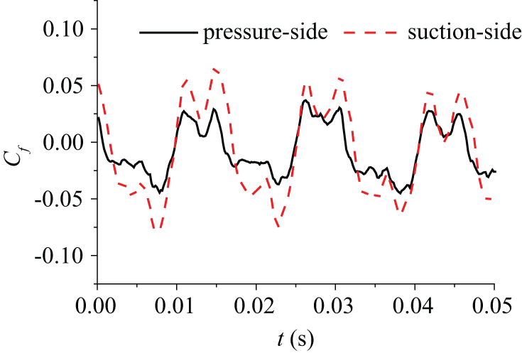
Force fluctuation transitions on pressure and suction surfaces of the impeller blades.
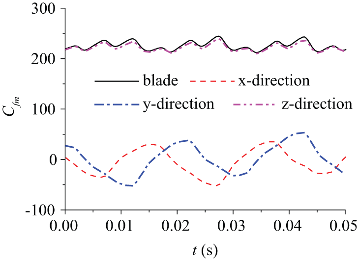
The force fluctuation transitions on impeller blades are shown in Figure 25. It can be seen that the dominant frequency of force fluctuation is the BPF, which is the same as the force fluctuation in the z-direction. In the x- and y-directions, the energy amplitudes of force fluctuations are higher, and there exist low-frequency signals. The spectra of force fluctuations on pressure side and suction side of the impeller blades are shown in Figure 26. On both sides, the dominant frequencies of force fluctuations are the BPF as well and the energy amplitude of suction side is higher than pressure side.

Spectra of force fluctuations on the impeller blades.
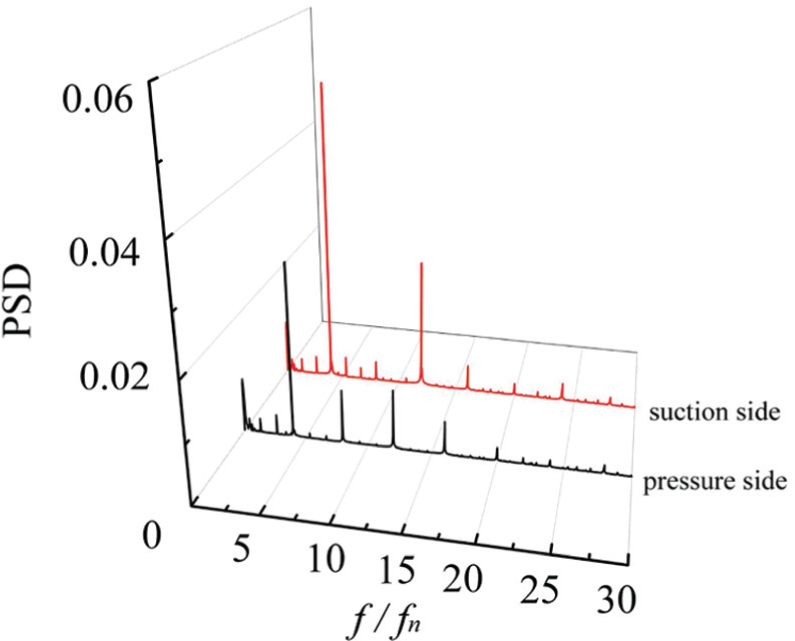
Spectra of force fluctuations on pressure side and suction side of the impeller blades.
Conclusion
The characteristics of the rotating turbulent flow in a centrifugal water pump with three asymmetrical diffusers have been studied through CFD numerical simulations. The behaviors of pressure and force fluctuations at selected monitoring locations of different parts of the pump are particularly analyzed in time domain and frequency domain. The main findings of this study are as follows:
At impeller inlet, the largest PFA locates at center region of flow passage. The PFAs are approximately the same near the hub and shroud walls. At impeller outlet, the largest PFA locates near the shroud. Compared with impeller inlet, the pressure fluctuation at impeller outlet is more unstable, and its amplitude is larger.
In diffuser domain, the largest PFA locates near the diffuser inlet and decreases along with the flow direction. The pressure fluctuation is stronger in the region near the solid boundary. The period of the pressure fluctuation at tongue is much longer than at other regions due to the existence of vortices.
The dominant pressure frequencies in the locations of impeller inlet, impeller outlet, and diffuser (except the region at tongue and diffuser outlet) are all in accordance with the BPF
The existence of the three asymmetrical diffusers has damping effect on the PFA and energy amplitude of pressure fluctuations in the diffuser domain dramatically, which indicates that the diffusers can effectively control the hydraulic exciting vibration in the pump.
The force exerted on the impeller blades is periodic and consists with the z-direction (rotating axis). The dominant frequency of force fluctuations is the BPF, which is the same as the force fluctuations in the z-direction.
Footnotes
Academic Editor: Moran Wang
Declaration of conflicting interests
The author(s) declared no potential conflicts of interest with respect to the research, authorship, and/or publication of this article.
Funding
The author(s) received no financial support for the research, authorship, and/or publication of this article.