
Abstract
To resolve the problems of ink drop tailing, satellite drop, and ink ribbon of piezoelectric ink-jet printing, a fluid dynamic modeling method and an adaptive ink-supply method are proposed. First, based on the volume of fluid method, a fluid dynamic model for the jetting and forming of ink drop is set up. According to this model, the numerical analysis for the states of forming, fracture, and flight of ink drops is performed; referring to different boundary conditions of piezoelectric ink-jet process, the inherent relations between ink characteristics and ink drop motion are analyzed, and an optimal viscosity range for piezoelectric nozzle is confirmed. Then, a fuzzy proportional–integral–derivative–based ink-supply control method is developed to achieve the fast and smooth responses for ink temperature and to obtain the required ink characteristics and ink-supply effects. Finally, a microcontroller-based piezoelectric ink-jetting experiment platform is established, and the experiment results show that the fluid dynamic modeling method can simulate the flow field profiles of piezoelectric ink-jet; the fuzzy proportional–integral–derivative–based ink-supply system can improve the printing quality; the print stripes are decreased obviously, and the softer and cleaner images can be obtained.
Keywords
Introduction
Ink-jet printing1–3 is a type of computer printing that drives ink spray to media surface and form text or image by transforming image information into electrical signal. The image information can be changed dynamically before printing, and it is the so-called variable printing. According to the format width (Od) and linear velocity (Ov), ink-jet systems can be divided into three categories: large-format ink-jet printer (Od > 0.42 m), high-velocity continuous ink-jet printing system (Ov > 1 m/s), and very-large-format ink-jet digital printer (Od > 1.5 m).4,5
With the developments of high-speed and high-precision ink-jet devices, the standards for print nozzle are raised to meet those increasing requirements. Many ink-jet nozzle suppliers including Kodak, Hewlett-Packard, Xaar, and Epson invest lots of resources to make improvement in speed, resolution, and integrations. However, the above studies pay much attention on the nozzle structures and pulse voltage characteristics of piezoelectric ink-jet. For printing industry, ink is consumed greatly but nozzle cost is higher and its service life gets longer. Due to these issues, the integration of nozzle and ink box cannot meet the basic requirements of continuous and effective production. Therefore, ink-supply system is an essential component for the variable information printing.6,7
Related research works4–9 suggested that ink-jet printing is a fluid movement caused by ink movements in pipe under the action of actuator, so the ink characteristics are the key point for high-quality print. Only the parameters of piezoelectric nozzle, amplitude, and period of drive pulse voltage as well as nozzle structure are matched with the ink characteristics, which results in high-quality print. At present, there are many specified inks used for specified nozzles that are supplied by specified manufacturers. For example, the nozzles made by Xaar have their specified ink type also made by Xaar. The non-universality of ink is one of the major barriers which hinder the extension of ink-jet printing. It leads to high cost and restricts the large-scale production. Since ink-supply system is like a buffer to ink characteristics, the appropriate ink can be supplied in time and keep its characteristics in suitable range. Accordingly, for the continuity, reliability, and high quality of ink-jet printing, it plays a practically significant role.
Bruce 10 carried on a liquid sprayed experiment to study the effects of liquid characteristics on the speed, separation distance, and stability. The results proved that the stability of polymer liquid and concentration has an inverse relationship. Pimbley and Lee 11 performed serial tests and researches on drops’ form and satellite drops and adopted Strobolux to measure the break distance of satellite. Bugdayci and Bogy 12 made researches on the relationship between liquid pressure and voltage in extrusion nozzle and concluded that the smaller difference between internal and external diameters will cause lower voltage for ink spraying. Lee 13 concluded that reliable ink injection was related to the parameters of amplitude, shape, and frequency of drive pulse; shape of ink in nozzle; supplied liquid level; and temperature. Wei et al. 14 implemented dynamics analysis on piezoelectric nozzle and found that piezoelectric device amplitude is proportional to the depth of ink cavity. Chen et al. 15 executed numerical simulation on parameters’ design of curved nozzle structure. Then, they found the relationship between volume factor and drop velocity and obtained a series of formulas to design nozzle structure parameters. Link and Semiat 16 adopted laser Doppler tachometer and image visualization system to observe the ink spraying process in large-format printer. And they found that print quality is affected by satellite drops. Then, the relationship between pulse voltage and ink-sprayed pressure was revealed. Wijshoff 17 performed researches on dynamic characteristics of piezoelectric nozzle from piezoelectric sensor, propagation of wave in pipe, and formation of drops. Shin et al. 18 analyzed the influence of temperature and drive pulse on the form of piezoelectric ink and concluded that the increase in temperature will lead to the decrease in liquid viscosity; the decrease in adhesion force will lead to the increase in capillary force in the nozzle; and the lift of temperature and drive voltage will cause the expansion of ink drop. Shin et al. 19 made analysis on the way of how double pulse control the form of low-viscosity ink drop and realized that the single droplet spray was hard to avoid in low-viscosity satellite drop spray. The relationship of drop velocity to interval time of double pulse and voltage amplitude was successfully obtained. Wu 20 built up a three-dimensional (3D) model for extrusion nozzle and made numerical simulation of the droplet form, flight, and strike processes. Then, experiments were carried on and the results were close to the simulations. By the simulation, the influences come from ink characteristics, and length of nozzle and pressure wave were found. Based on the Navier–Stokes (N-S) equations, Yu et al. 21 developed an improved level-set way especially for ink-jetting quadrilateral meshes in simulation and used it to make simulation of the boundary change of gas–liquid two-phase flow under the action of drive pulse. Shi 22 set up a dynamic model for drop size and velocity prediction and concluded the following: for the form of drop, the increase in the viscosity will slow down it; however, the density and surface tension have little effect on it. Shi 23 made researches on dynamic characteristics of ink viscosity, spray velocity, and process of drop landing and found the way to determine the optimum nozzle structure by pressure and velocity.
From the above references, it can be concluded that many scholars had performed studies on the mechanisms, dynamic characteristics, and drop spray processes of piezoelectric nozzle. They modified and collected the photos of ink forming and flying process in nozzle structure through different mathematical models and obtained the relations between nozzle structure, spray velocity, ink size, and the form of satellite drops. Moreover, they put forward a series of calculation formulas of ink-jet parameters and design criterions for nozzle structure to improve the stability and efficiency of ink spraying. However, most of them preferred to the development of piezoelectric nozzle and focused on the nozzle structure and drive pulse voltage. There is still a lack of researches on the dynamic mechanisms of ink drop forming and ink drop flight process, which are affected by the ink characteristics.
To address the issue, this article introduces the computational fluid dynamics (CFD) into piezoelectric ink-jet printing area and puts forward a fluid dynamic modeling method for piezoelectric ink-jetting process, and the variation regulars for the states of forming, fracture, and flight of ink drops will be revealed. In combination with different boundary conditions of piezoelectric ink-jet process, the inherent relations between ink characteristics and ink drop motion are analyzed, and an optimal viscosity range for piezoelectric nozzle is confirmed. Then, two control methods are proposed to increase the stability of ink spraying: adjusting ink characteristics by the temperature and modulating ink-supply pressure according to liquid level. Subsequently, an independent ink-supply subsystem based upon microcontroller is developed to obtain the required ink characteristics for continuous ink-supply. Finally, the comparative experiments are performed to verify the effectiveness of the proposed methods. This research can not only provide theoretical references to modeling–solving of high-speed fluid jetting process involved in the industrial areas of precise machining or micro-chemical reactors, but can also offer universal technical supports for design and optimization of jetting nozzles and fluid medium supply systems.
This article is organized as follows. In section “Fluid dynamic model of piezoelectric ink-jet,” the fluid dynamic model of piezoelectric ink-jet is set up. In section “Numerical simulation of ink-jet,” numerical simulation for the ink-jetting process is performed and the results and discussion are presented. In section “Fuzzy PID-based ink-supply method,” the embedded ink-supply system is developed, and the fuzzy proportional–integral–derivative (PID)-based ink-supply control method is proposed. In section “Experiments and results analysis,” the printing experiments are performed, and the comparative results are analyzed. In section “Conclusion,” the conclusions are presented.
Fluid dynamic model of piezoelectric ink-jet
Physical model of ink-jet
Piezoelectric jet depends on the voltage pulse driving of piezoelectric transition (lead zirconate titanate (PZT)) components, in which the PZT components are controlled by pulse width modulation (PWM)24,25 to perform ink jetting and supply.
Piezoelectric jet transforms energy from electrical pulse signal to mechanical motions. This process can be divided into three stages. (1) The PZT component is turned on and expands, which makes the ink cavity expand and absorb ink. (2) The PZT component is turned off and makes the ink cavity contract, where the contracted force presses the ink to jet through the cavity. (3) Ink being supplied from the nozzle, the negative pressure of ink cavity causes the ink fracture into an ink drop that can fly independently. In these three stages, there is no significant difference between fluid dynamics in pipe and near nozzle. In order to consider the characteristics of ink jetting process better, a simplified physical model for piezoelectric ink-jet is set up, as shown in Figure 1.

Simplified physical model of piezoelectric ink-jet.
From Figure 1, we can find that the left of gas–liquid interface is nozzle connecting with ink cavity, and the right is air which is the flight area of ink. The fluid in ink-jet process belongs to gas–liquid two-phase flow, and it can be described by N-S equations, in which the ink-jet boundary conditions should meet the motion characteristics of fluid interface.26–28 In this study, we focus on the changes in gas–liquid, and the following assumptions should be satisfied: (1) fluid is the incompressible non-Newtonian fluid; (2) fluid flow belongs to laminar flow and ink cavity condition belongs to non-slip boundary condition; (3) the parameters of liquid characteristics are constant; and (4) the pressures on nozzle are uniform.
Dynamic model of ink-jet
It is well known that there are three multiphase-flow models in fluid dynamics: volume of fluid (VOF) model, mixture model, and Eulerian model.29–31 VOF model is a surface-tracking method with Eulerian mesh, in which all fluid components share same momentum equations. During the course of calculation, all volume fractions of each multi-component in every calculation unit should be recorded. This model can be used for the objectives with incompatible fluid interfaces. For the mixture model, there are four features: each phase is treated as a continuum, the mixture is solved by momentum equations, the discrete phase is described by relative velocity, and it can be applied to continuous multiphase-flow model with relatively homogeneous velocity. Eulerian model includes momentum equation and continuity equation and is the most complex multiphase-flow model.32,33 For the ink-jet process, ink acts as incompressible flow and with free boundary interfaces for the drop flight. In this article, we need more care for gas–liquid interface variation and drop-forming process, so the VOF model is a better choice.
By solving the independent momentum equations and the volume fraction of each fluid passing through the region, two or three immiscible fluids can be simulated in VOF model. The sum of volume fraction in each unit is 1, and the governing equations are combined as follows.
Volume fraction equation
In VOF model, the tracking of interface between phases can be accomplished by solving the continuity equation of single-phase or multiphase volume fraction. For the q phase, the equation can be describes as follows

In equation (1), αq is the volume fraction of the q phase and υq is the velocity. The fluid volume function in each unit is the ratio of fluid volume and unit volume. αq = 1 means grid is full of fluid, called fluid grid; αq = 0 means there is no fluid in grid, called void grid; 0 < αq < 1 means there is gas-liquid interface in grid, called surface grid.34–37
Momentum equation
By solving the single momentum equation in the whole area, the velocity obtained from the equation shares the same characteristics in multiphase. Momentum equation depends on the volume fraction of all phases in ρ and μ

In equation (2), ρ is the density, p is the pressure, η is the viscosity, υ is the velocity, and F is the body force. The variation rate of the control body oriented to time is equal to the sum of external force.38–41
Energy equation

In equation (3), ρ is the density, E is the energy, υ is the velocity, p is the pressure, keff is the effective thermal conductivity, T is the temperature, and Sh is the heat source phase. This formula means that the value-added rate is equal to the sum of the net heat flux and the work of body force as well as area force to control body.42–44
Solving methods
Based on the above hypothesis, the flow field solving for ink-jetting process can be described as follows: by finite volume method or other similar method, the computational domain can be discretized into many small elementary volumes and the governing equations in each elementary volume can be solved. For the above-mentioned process, there are coupled method and segregated method that can be used to solve the equations. In this article, we use the pressure correction method to solve fluid equation and temperature field, in which the implementation method is the semi-implicit method for pressure-linked equations (SIMPLE).
The SIMPLE algorithm is for the pressure field, and it can be an assumption value or resulted from iterative calculation. Therefore, we can solve discrete momentum equation to obtain velocity field. Because pressure field is assumptive, the velocity obtained may not satisfy the continuity equation, and thus, we must revise the pressure field. Accordingly, the pressure field and velocity after revision must meet the continuity equation in next iterative calculation. Referring to this rule, the relationship between pressure and velocity can be obtained from discretizing momentum equation. Substituting it into discretizing continuity equation, we can obtain the pressure correction equation, and by this equation, pressure correction value can be obtained. Then, by the new obtained pressure field, new velocity equation can be obtained and it can be made sure whether the velocity is convergent. If unconvergent, the pressure field after revision can be used as the new pressure field and next iterative calculation can be started. Repeat the process until the convergent solution is obtained. To start the iterative process, we need initial and assumptive pressure as well as velocity field. As iterative process begins, the pressure and velocity field improved, so the pressure and velocity will be near to the true solution.
Numerical simulation of ink-jet
Numerical model and boundary conditions
According to the physical model in section “Fluid dynamic model of piezoelectric ink-jet,” the assumptions of numerical model can be described as follows: incompressible fluid, laminar flow, low Reynolds number, and non-slip boundary condition. Based on the above hypothesis, a two-dimensional (2D) single precision solver is selected. Since there is no negative volume, we choose unsteady time model, read profile file, define condition exercises, and set grid update model as smooth spring analogy model and elastic modulus as 0.05. After setting those parameters, the numerical model is initialized for solving the process.
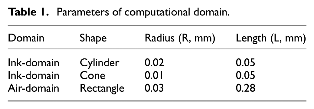
Ink-jet process includes the ink forming and flight process. So, it is necessary to build the model for nozzle and flight zone. According to the geometric parameter of piezoelectric nozzle and the distance between nozzle and substrate, the 2D symmetry computational domain can be confirmed. Generally, the distance between nozzle and substrate is less than 1 mm, and this distance will be shorter in ink form process. Combining the calculating time and effectiveness while simulation, it is better to set air length as 0.28 mm, and the parameters are presented in Table 1.
Parameters of computational domain.
Considering the numerical simulation, grid number has positive relativity on the calculation precision and scale, and the calculation time will increase with the enlargement of scale. Therefore, to improve the effectiveness and keep enough precision, local mesh subdivision, that is, the key part, should be subdivided further. In addition, mesh subdivision is a critical technology that will influence the precision of the simulation results. In this article, we use quadrilateral mesh to devise the model, and 53,838 meshes are obtained, as shown in Figure 2. To perform the repeatability of numerical simulation, we set boundary type as inlet, outlet, and wall and also make independence verification.

Numerical model of piezoelectric ink-jet.
To get enough simulation precision for the drop forming and flight process, we choose 2D double precision solver, and the setting procedures are as follows. (1) Since there are many instantaneous droplet-shape changes in ink-jet process, we choose the pressure solver with non-stationary time solutions. (2) For the micron-size nozzle, ink-jet is influenced greatly by surface tension, which regards the surface tension as continuous force across the surface and equal to body force in momentum equation. It can be used to solve the surface tension problems beyond limiting effects from free surface. Moreover, we should take the action of wall contact angle into consideration. Under the surface tension and negative pressure, ink will form half-moon shape when nozzle is unworked. In this case, the angle between the fluid tangent and horizontal line of nozzle is the contact angle. (3) For the position of reference pressure and gas–liquid interface, the horizontal ordinate is 0.1 mm and the vertical is 0.03 mm.
With respect to the boundary conditions, we use pressure outlet and set reflux 0. In addition, inlet condition is the key factor to numerical simulation. According to the pressure-wave propagation theory, the inlet pressure from PZT will be transformed to the pressure in nozzle and wall boundary condition, as shown in Figure 3. Concerning the viscous flow, non-slip condition is the default condition of wall, but it also can be changed by shear to define the slip wall or define tangential velocity component by the translation or boundary domain rotation. In this study, we use non-slip rigid boundary condition, in which the ejector is static, while liquid moving, and the velocity of liquid in wall is 0.
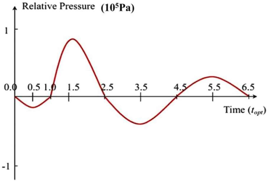
Relative pressure of nozzle inlet.
The ink velocity of inlet is a function about time variable, with the compression and recovery processes in each ink drive process. For the compression, ink is pressed out from nozzle and forms the ink drops. Regarding the recovery process, the driving parameters are initialized and ready for the next jetting, where the drive energy can be shown through velocity and pressure. When the nozzle structural parameter and pulse frequency have been curtained, drive energy increase will lead to voltage amplitude and velocity increase. Thus, we take inlet velocity as the inlet boundary condition. However, related simulation results show that ink-jet is mainly connected to the first group of velocity change, so we simplify the inlet velocity into cosine function with semi-period and define the inlet velocity by user-defined function (UDF).
The function of UDF mainly depends on DEFINE macro. By the DEFINE_PROFILE, the source code is defined to provide the outline information of boundary conditions for the solver. For the ink-jet process, a UDF can be described as follows:
#include "udf.h"/*head file*/
DEFINE_PROFILE(inlet_x_velocity, thread, index)
{
real x[ND_ND];/* position vector */
real y;
float f;
begin_f_loop(f, thread)
{
F_CENTROID(x, f, thread);/*obtain the center coordinate of the unit */
y = x[1];
F_PROFILE(f, thread, index) = 20-y*y/(0.0745*0.0745)*20;/* obtain the velocity*/
}
end_f_loop(f, thread)
}
The parameter inlet_x_velocity in DEFINE_ PROFILE defines the function of inlet velocity. In the boundary domain, all units will be applied to the equation in this function. The parameter thread will be defined automatically when UDF is elected as the boundary conditions in CFD user interface. Subscripts are automatically defined by the begin_f_loop macro, which is applied to the loop through all cell faces in the boundary domain in UDF. For every face, the coordinate of the face centroid can be obtained from F_CENTROID macro. The Y-coordinate is used in parabolic equation and velocity value is obtained from F_PROFILE macro. Besides, begin_f_loop macro and F_PROFILE macro can be obtained from CFD macro group. Finally, by the region adapter-patch, the ink domain is initialized to make the volume ratio of liquid phase to 1.
Numerical results and discussion
Simulation scheme
Ink viscosity and surface tension have critical influences to piezoelectric ink-jet. To obtain the adequate matching relationship between ink viscosity, surface tension, and piezoelectric nozzle, we perform simulations about the two parameters individually.
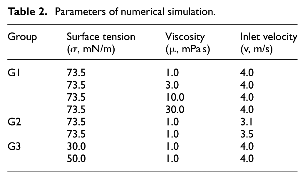
Based on the assumptions in section “Numerical model and boundary conditions,” in combination with the former research works, the physical parameters for piezoelectric ink-jet process simulation are configured as follows: ink viscosity ranges from 1 to 60 mPa s, jet velocity of nozzle changes from 4 to 6 m/s, velocity in inlet varies from 2 to 4 m/s, and surface tension of ink is similar to water surface tension. Consequently, the numerical simulations can be divided into three groups, and the parameters are listed in Table 2.
Parameters of numerical simulation.
Results and discussion
The first group of numerical simulation mainly considers the two-phase volume fractions of ink-jet flow filed, with the variations in surface tension, and the results are shown in Figure 4, where the light region represents the ink phase and the dark region represents the gas phase.

Two-phase volume fractions of ink-jet flow filed with different surface tensions (σ = 73.5 mN/m, v = 4.0 m/s): (a) μ = 1 mPa s, (b) μ = 3 mPa s, (c) μ = 10 mPa s, and (d) μ = 30 mPa s.
From Figure 4, the following conclusions can be obtained. (1) For the ink drop tailing, the tail length is with the maximum value when the ink viscosity is 1 mPa s, as shown in Figure 4(a). There are three satellite drops following the main ink drop, in which two of them are close to the main drop and make the main drop into a larger one; the third satellite drop flies independently. With the increase in ink viscosity, the ink tail length becomes shorter, and there is only one satellite drop formed and it quickly combines to the main drop when viscosity is 10 mPa s, as shown in Figure 4(c). (2) Concerning the satellite drop, with the increase in viscosity, the drop number will decrease and it will be harder to combine to the main droplet. When viscosity is up to 10 mPa s, satellite droplets decrease to one and it will combine to the main droplet; if the viscosity is 30 mPa s, there are no satellite drops, as shown in Figure 4(d). The above results can illustrate that the higher viscosity can restrict the formation of satellite drop. (3) With respect to the velocities of ink drops, they are influenced by the ink viscosity obviously; the higher viscosity can create lager motion resistance, so the velocities of drops will decrease as viscosity increases.
The second group analyzes the two-phase volume fractions of ink-jet flow filed with different inlet velocities, and the results are shown in Figure 5.

Two-phase volume fractions of ink-jet flow filed with different inlet velocities (σ = 73.5 mN/m, μ = 1 mPa s): (a) v = 3.1 m/s and (b) v = 3.5 m/s.
From Figure 5, we can observe the next profile regulars. (1) With the increase in inlet velocity, the initial kinetic energy of ink flow tends to be higher, and the length of the ink tail will increase. (2) The higher velocity is apt to form the satellite drops and can make them exist for longer time. As shown in Figure 5(a), under the condition of v = 3.1 m/s and t = 26 μs, the satellite drop has combined to the main drop; at the same time point, in Figure 5(b), there is an integral satellite drop. (3) Because of the reduction in initial energy, when ink viscosity is small (μ = 1 mPa s), satellite droplets decrease visually, and the form of droplets and the stability of ink flight become well, but ink-jet velocity will decelerate. The third group analyzes the two-phase volume fractions of ink-jet flow filed with different surface tensions, and the results are shown in Figure 6.

Two-phase volume fractions of ink-jet flow filed with different surface tensions (μ = 1 mPa s, v = 4.0 m/s): (a) σ = 30 mN/m and (b) σ = 50 mN/m.
From Figure 6, the following regulars can be inferred. (1) The decrease in surface tension will lead to long drop tailing. (2) The separation time of main drop and satellite drop will increase as the surface tension decreases. (3) With the increase in surface tension, the drop shape tends to be circular; on the contrary, the shape will be close to ellipse. (4) The smaller surface tension is apt to create the main drop and more satellite drops faster.
Fuzzy PID-based ink-supply method
Architecture of ink-supply system
For the objective of this article, the ink-supply system contains primary ink box, secondary ink box, ink pump, filter, and feedback control system, as shown in Figure 7.
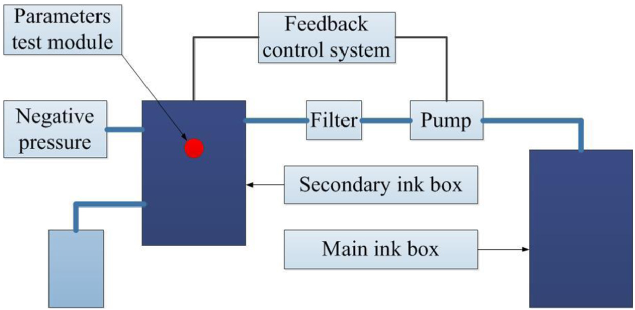
Schematic diagram of ink-supply system.
Primary ink box is the main ink storage device of ink-supply system. There are three holes in the box: ink outlet hole, ink inlet hole, and air hole. Ink-supply system is used to control the ink temperature and liquid level. This function is accomplished in secondary box, thus secondary box is the key part of ink-supply system. There is a change process for temperature, which is a typical time-delay inertial physical process. By thermodynamics formulae, we can obtain the heat energy for temperature change

where Q is the heat energy, C is the specific heat capacity, m is the mass, and T is the temperature.
Since heat energy is positive to the quality and equal to the work done, we can obtain the following

where P is the power consumption and t is the time. According to equations (4) and (5), equation (6) can be obtained as follows

With the same power consumption constant, the time is negative to the quality. Moreover, the following fittings need to be performed: replaceable single-line ink filter to keep the ink flow smooth in pipe, air filter to prevent the air from pollution, and hose to connect each fitting.
Fuzzy PID-based control method for ink supply
Referring to the functional requirements of piezoelectric ink-jet printing, we design an ink-supply control system based on STC12C5628AD microcontroller, 45 as shown in Figure 8. By receiving analog signal from sensors, acquisition circuit, and amplifier, the microcontroller will perform analog/digital (A/D) transformation and PWM generation. Then, by the PWM signal sequence, actuator will make a series of actions and show the system state on the screen. Moreover, a serial port is applied for control panel to implement instruction communication and variable update.46–48
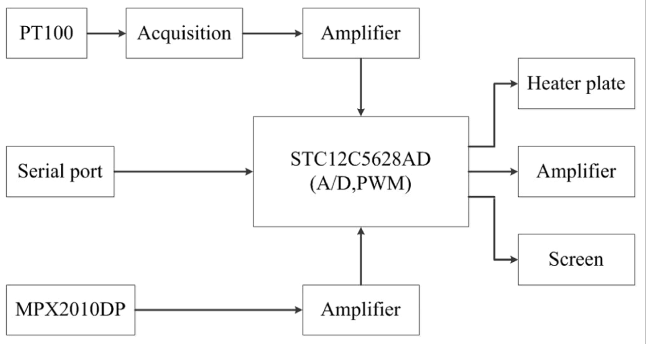
Microcontroller-based ink-supply control system.
In Figure 8, there is a pressure sensor MPX2010DP, which acquires the bottom pressure and regulates the liquid level. With respect to nozzle work frequency, ink velocity, and flow in ink pump, the threshold value for opened pump is 65 mm and for closed pump is 98 mm. Consequently, a control subsystem for liquid level is proposed, as shown in Figure 9.

Flow chart of liquid-level control subsystem.
During sampling period, when liquid level is lower than 65 mm and there is no trend that shows liquid level will raise, it means liquid level in main box is lower than 65 mm. Then, liquid switch will be turned off, the pump will stop working, and warnings will be displayed in screen. If ink liquid level is still down and reaches 62 mm, serial port will send warning signal to control system, and the print task will be stopped.
In the secondary ink box, there are three temperature sensors, and the ink temperature can be calculated by sensor resistance variations. Temperature change process is a large-inertia nonlinear time-varying process. However, temperature is one of the key points to the system, so we need to get real-time temperature response. One of the ways is to divide the temperature rising process into three processes: temperature fast-rising, temperature slow-rising, and temperature maintaining, as shown in Figure 10.

Temperature profile of secondary ink box.
Concerning the complexity of the temperature control for piezoelectric ink-jet, traditional PID algorithms require complicated adjustments and depend too much on empirical data. 49 With respect to the complicated production and control process, it is hard to build an accurate model to perform the required control effects. According to the results in section “Numerical simulation of ink-jet,” the ink-jetting process is with nonlinear characteristics corresponding to the variations in ink temperature.
To address the above issue, a fuzzy PID algorithm for piezoelectric ink-jet is proposed. The algorithm is the organic combination of fuzzy inference and PID control, as shown in Figure 11. It can perform the inference calculation for the objectives with nonlinear time-varying processes, so the optimal PID parameters can be obtained to make the controlled objective be with nice static and dynamic properties.
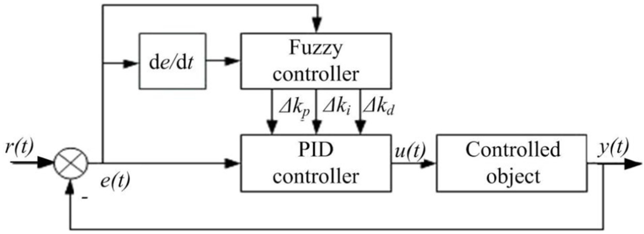
Fuzzy PID controller for piezoelectric ink-jet.
In Figure 11, the system bias e(t) and bias rate de/dt are the inputs of fuzzy control, and the outputs of fuzzy control can respond exactly the inputs of PID control. Then, actuator will perform actions under the control of PID. Based on the algorithm route, the control procedures are presented in Figure 12.

Flow chart of fuzzy PID control algorithm.
Experiments and results’ analysis
Experimental platform
In this study, ink-supply system is an independent mechatronics system which has its own control and it is applicable for different nozzles. Due to negative pressure supply in secondary ink box, its assemblage position must match the nozzle position. According to nozzle characteristics, liquid level in ink box should be 10–50 mm lower than nozzle. Thus, the ink-supply system consists of two parts: secondary ink box and cabinet. The cabinet includes primary ink box, ink pump, filter, control panel, screen, and power. Taking integration and convenience into consideration, the cabinet is 40 cm long, 10 cm wide, and 30 cm high. There are some location poles for control panel, ink pump and power, ink pipe, wire, and screen inlay slot in cabinet, as shown in Figure 13(a).

Experimental platform for piezoelectric ink-jet: (a) ink-supply system and (b) display of temperature and liquid level.
System adjustment includes getting A/D reference voltage and zero compensation procedure of AD620, OP07, and MPX2010DP. In addition, for hysteretic parameters such as liquid level and temperature, we need to adjust control period and make continual adjustments to obtain accuracy and optimum value. The optimum value is presented in Figure 13(b). According to the experimental results, at 18°C with ink box full of ink, after 9′16″, ink-supply system will be steady in 30°C with 0.4°C deviation. In this system, viscosity and fluidity are controlled by temperature adjustment, and the working state parameters will be shown in screen. Moreover, there is RS232 communication interface in control panel, connecting ink-supply system and console.50,51
Experimental results and discussion
It can be observed from the images shot with charge-coupled device (CCD) per 50 μs in an image acquisition system that a complete droplet forming process is obtained, as shown in Figure 14.

The forming process of ink drops: (a) ready state, (b) ink extrusion, (c) t = 0 μs, (d) t = 50 μs, (e) t = 150 μs, (f) t = 200 μs, (g) t = 250 μs, (h) t = 300 μs, (i) t = 350 μs, (j) t = 400 μs, and (k) t = 450 μs.
Figure 14(a) is an image of system ready state, and there is a horizontal line in nozzle. Figure 14(b) represents the moment the system just begins to work. When the system works under the feeding pressure and with the firing pin in nozzle, with the resistance to surface tension and viscosity, fluid will remain as a residue in nozzle. Figure 14(c)–(k) describes the whole forming process of an ink drop. Due to firing pin’s impact, local pressure increases instantly. The balance between surface tension, fluid pressure, and viscosity resistance is broken and the fluid is pressed from nozzle.
Figure 14(c)–(e) shows that the liquid out of nozzle is getting longer and longer. Surface tension makes the droplet to form the spherical shape and local pressure will reduce with the decrease in firing pin’s impact. At that moment, because the speed at droplet front-end is faster than back-end, droplet will be longer, and by surface tension, jet flow rheostriction will appear, as shown in Figure 14(f). Due to prolonged rheostriction, the fluid finally divides into two parts. The front part will be sprayed with a thin tail and the back part cannot overcome the surface tension and viscosity resistance and hence finally returns to the liquid in nozzle. This process can be observed from Figure 14(g) to (k).
From the above results, the inherent relationship between the ink characteristics and the formation of drops can be obtained. Subsequently, to check the effectiveness of the numerical simulation, an observation experiment for the ink-jetting process is performed, and the results are shown in Figure 15.

The actual ink-jet process (μ = 1 mPa s, v = 4.0 m/s, and σ = 50 mN/m): (a) t = 10 μs, (b) t = 16 μs, (c) t = 20 μs, (d) t = 22 μs, (e) t = 24 μs, (f) t = 26 μs, (g) t = 32 μs, and (h) t = 36 μs.
The initial stages of ink-jet are shown in Figure 15(a) and (b), in which the liquid velocity in nozzle changes as the law of one-fourth sine. Due to viscosity resistance and surface tension, the liquid in nozzle forms the crescent shape and then forms cylinder shape gradually. In Figure 15(c), the liquid velocity reduces and rheostriction begins. Then, rheostriction becomes obvious, and the long tail droplet is formed. Figure 15(e) and (f) are the forming stages of satellite droplets. Because of velocity differences and interfering factors, drop tail is broken and satellite droplets are formed. In Figure 15(g), the velocity of satellite droplet near the main droplet is faster than the main droplet and finally combines with main droplet. However, the other satellite droplets fly themselves, as presented in Figure 15(h).
In order to verify the advantage of the proposed fuzzy PID ink-supply control method, a model machine of the piezoelectric ink-jet system is developed, as shown in Figure 16.

Model machine of the piezoelectric ink-jet system: (a) printing device and (b) ink-supply system.
Based on the above model machine, the comparative printing experiments have been performed. The experiments contain two groups: the first group is without the fuzzy PID-based ink-supply system (as shown in Figure 17(a)) and the other is with the proposed control system (as shown in Figure 17(b)). From Figure 17, we can find that the proposed fuzzy PID-based ink-supply system can improve the printing quality, in which the print stripes are decreased obviously and image looks softer.

The results of the comparative printing experiments: (a) without the ink-supply system, (b) using the ink-supply system, (c) amplified characteristics of (a), and (d) amplified characteristics of (b).
For verifying the local detailed differences in the two groups of experiments, two local regions are selected, and the amplified characteristics are shown in Figure 17(c) and Figure 17(d), respectively. By the real-time and continuous adjustments of ink-supply system, ink characteristics are always kept in a suitable range that satellite drops are more difficult reversely to form in ink spray process. Thus, there is no extra drops scatter randomly to the media surface and the image with ink-supply system will look clearer.
Conclusion
Current piezoelectric ink-jet printing systems have the problems of ink drop tailing, satellite drop, and ink ribbon. This article addresses the issues by presenting a fluid dynamic modeling method and an adaptive ink-supply method. For the above research target, the corresponding research works have been performed, and the main conclusions are as follows:
According to the working principle, a simplified physical model for piezoelectric ink-jet printing is set up. In combination with the VOF method, a fluid dynamic model for the jetting and forming of ink drop is developed. Based on this model, the numerical analysis for the states of forming, fracture, and flight of ink drops is performed; the inherent relations between ink characteristics and ink drop motion are analyzed, and an optimal viscosity range for piezoelectric nozzle is confirmed. The simulated results show that the ink tail length becomes shorter with the increase in the ink viscosity; the higher viscosity can create larger motion resistance, so the velocities of drops will decrease as viscosity increases; the higher velocity is apt to form the satellite drops and can make them exist for longer time; the decrease in surface tension will lead to obvious long drop tailing.
A fuzzy PID-based ink-supply control method is developed to achieve the fast and smooth responses for ink temperature and to obtain the required ink characteristics and ink-supply effects. Finally, a microcontroller-based piezoelectric ink-jetting experiment platform is established, and the experimental results show that the proposed fluid dynamic modeling method can simulate the flow field profiles of piezoelectric ink-jet; the proposed fuzzy PID-based ink-supply system can improve the printing quality, in which the print stripes are decreased obviously, and the softer and cleaner images can be obtained.
In general, the main scientific contribution of this article is introducing the CFD methods into piezoelectric ink-jet printing area and proposing a fluid dynamic modeling method for piezoelectric ink-jetting process. This research can not only provide theoretical references to modeling–solving of high-speed fluid jetting process involved in the industrial areas of precise machining or micro-chemical reactors, but can also offer universal technical supports for design and optimization of jetting nozzles and fluid medium supply systems. The future research works will be performed on the facets of mesoscopic scale modeling and particle image velocimetry.
Footnotes
Academic Editor: Nima Mahmoodi
Declaration of conflicting interests
The author(s) declared no potential conflicts of interest with respect to the research, authorship, and/or publication of this article.
Funding
The author(s) disclosed receipt of the following financial support for the research, authorship, and/or publication of this article: This research was supported by the NSFC-Zhejiang Joint Fund for The Integration of Industrialization and Informatization (U1509212), the Zhejiang Provincial Key Innovation Team (2011R50011), and the Key Program for International S&T Cooperation Projects of China (2014DFE60020). This financial support is gratefully acknowledged.