
Abstract
Vapor-compression systems are still the most widely used type of automotive cooling systems despite their high energy consumption and negative environmental effects. This article gives a review of the carried out developments and the future trends for this type of automotive air-conditioning systems which have served vehicle occupants for more than 50 years. After going over a brief historical progression of the system, the circulating refrigerant developments were presented. Only few refrigerants meet the imposed attributes (e.g. zero ozone depletion potential, low global warming potential), and CO2 as well as R1234yf have a big potential to be the future refrigerants. Then, the developments related to the other major system components were outlined. In this context, the future trends show that the scroll compressor besides the evaporator and the condenser having parallel flow and micro-channels are the most promising for the next generation of (air-conditioning) systems. Concerning the control of the compressor and the expansion device, the advanced electronic control is the most attractive for the future systems. This is due to its provision to better improvement for the air-conditioning system performance. The present vapor-compression air-conditioning systems still have some weaknesses despite their eminent achieved improvements. Models developed for air-conditioning systems still have some shortcomings (e.g. low accuracy). Also, the test procedures for air-conditioning extra fuel consumption are still not worldwide in all aspects. Therefore, more efforts should be made to solve these problems.
Keywords
Introduction
Transportation vehicles, the horse of the modern societies, are one of the biggest energy consumers. The world fleet of automobiles is about 1 billion, 1 projected to double by 2035, and it consumes hundreds of billions of fuel gallons per year. In this context, transportation accounts for about 30% of all energy consumption worldwide, 2 and more than 90% of this energy comes from fossil fuels.
The high dependence of vehicles on fossil fuels has produced serious negative impacts on the environment. Also the extended use of their air-conditioning (A/C) systems, due to climate changes, has led to a significant increase in the energy consumption. In fact, the United States alone consumes approximately 7.1 billion gallons of gasoline each year for vehicles (A/C) systems. 3 This remarkable increase in consumption has placed vehicle (A/C) as the second largest consumer of the fossil energy after the vehicle propulsion. Furthermore, the automotive consumption of energy and their environmental impact will increase more in the near future as about 3 billion vehicles are predicted to be used. Based on the previous considerations, significant research efforts are devoted during the last 50 years to improve the automotive vapor-compression systems. In this article, the developments related to the vapor-compression (A/C) components and refrigerant (classification, evolution improvement, comparison) are reviewed and the future trends are presented. Also the different modeling approaches for these cooling systems are discussed. Furthermore, the development related to A/C test procedures is outlined.
Typical vapor-compression A/C system for automobiles
The automotive A/C systems are designed to control the temperature, humidity, and air circulation within the vehicular cabin for producing comfortable conditions. This task is accomplished by a number of major components (compressor, condenser, evaporator, expansion valve, and dryer) and secondary ones such as fans and sensors. A refrigerant circulates and experiences a series of processes along the refrigeration cycle. A typical vapor-compression A/C system is shown in Figure 1.
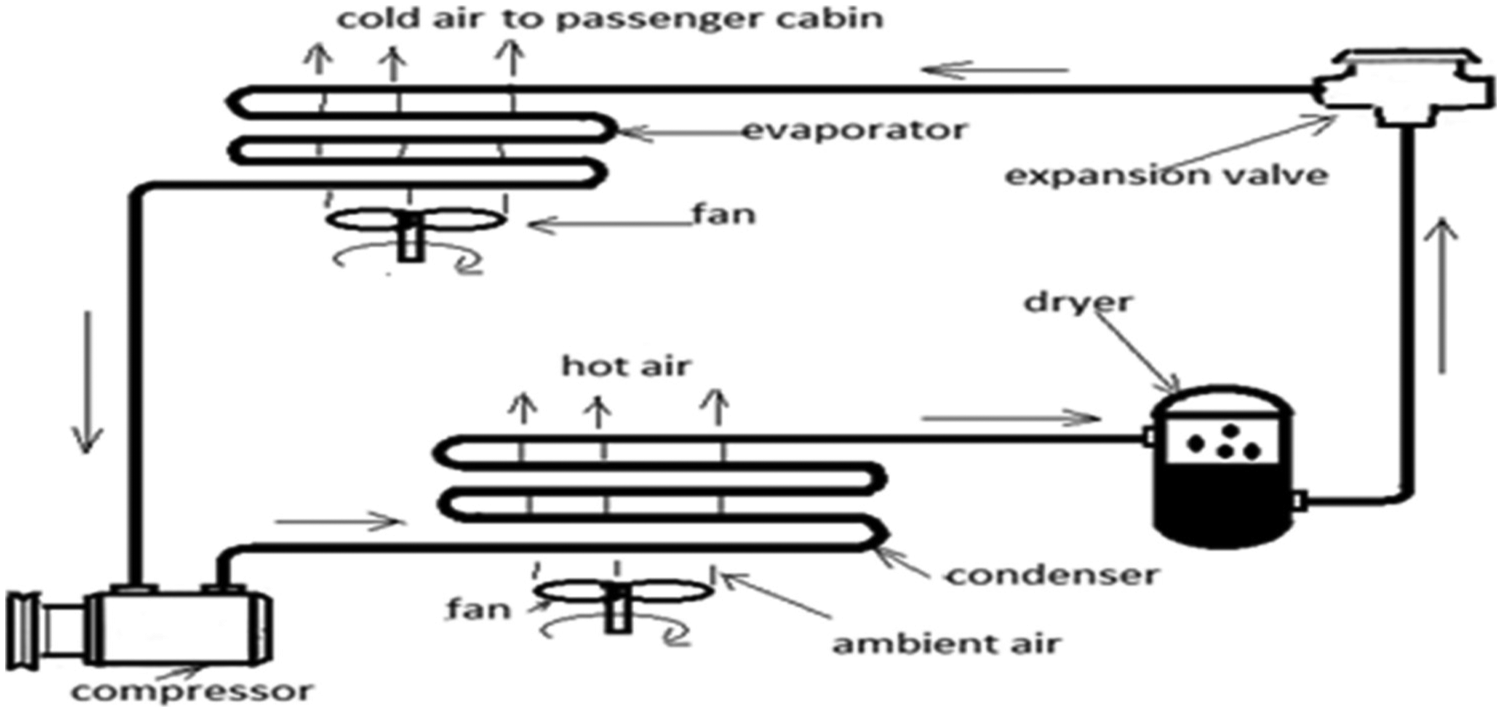
Components of a typical conventional A/C system for automobiles.
Brief historical review of automotive A/C systems
Since the advent of automotive air-conditioner in the 1940s, many improvements have been introduced in the first prototype of these cooling systems, in addition to the design of numerous alternative ones which are still unable to compete with the vapor-compression systems. In fact, significant advances can be distinguished between the oldest automotive A/C system which is composed of just a simple ventilator and air vents at the windscreen base. The sophisticated recent A/C system has reached a stage in which the desired cooling temperature as well as the other variables can be set by a computerized automatic temperature control. Based on a number of studies,4,5 the remarkable historical advances of automotive A/C systems can be outlined as follows:
The first factory A/C system was installed on Packard car in 1940. But it had many problems and the most affecting one is the absence of compressor clutch. Therefore, the driver has to remove the engine belt from the compressor pulley each time he wants to stop the A/C.
A significant vehicular expansion of A/C systems in the United States was in 1969. Indeed, 50% of all new cars sold were equipped with A/C systems.
For other industrialized countries such as European Union and Japan, A/C expansion took more time and 50% of new cars were not conditioned until 2000.
The most worldwide expansion of A/C systems was in 2010 and more than 99% of new cars were conditioned in the United States, Europe, and other countries.
Now let us go over the developments made for the main components of vapor-compression A/C systems.
Developments related to the circulating refrigerant
During the 100 years that have followed the advent of refrigerants in 1830, the cooling systems were not yet introduced in vehicles, thus the primitive refrigerants of that time, which were some solvents and volatile fluids, were not used for automotive cooling. A comprehensive study 6 has presented different types of refrigerants (not devoted to automotive cooling) from their advent to the future trends. In the last century, automotive refrigerants have been introduced and have undergone many developments.7–9 Based on the previous studies, the following milestones in succeeding decades can be specified:
In the 1930s, the first category of automotive refrigerants (fluoro-chemical type such as R-12 and R-22) has been employed for the first time in automotive A/C systems. These refrigerants have been used for about a half of that century because of their satisfaction to some essential requirements (e.g. safety and durability).
In the 1970s, environmental concerns have been raised and scientists have found that chlorofluorocarbons (CFCs) have links to the ozone layer depletion. Hence, a new category of refrigerants for automotive cooling systems was invented and the predominant one was R-134a. These alternatives must have zero ozone depletion potential (ODP).
Starting from 1990, massive changeover of R-12 to R-134a has taken place in the United States, Europe, and Japan. This replacement process has been completed by 1994. However, in the rest of the world, the transition to R-134a was not as fast as in the industrial countries. Figure 2 shows the successive developments of the automotive A/C refrigerants.
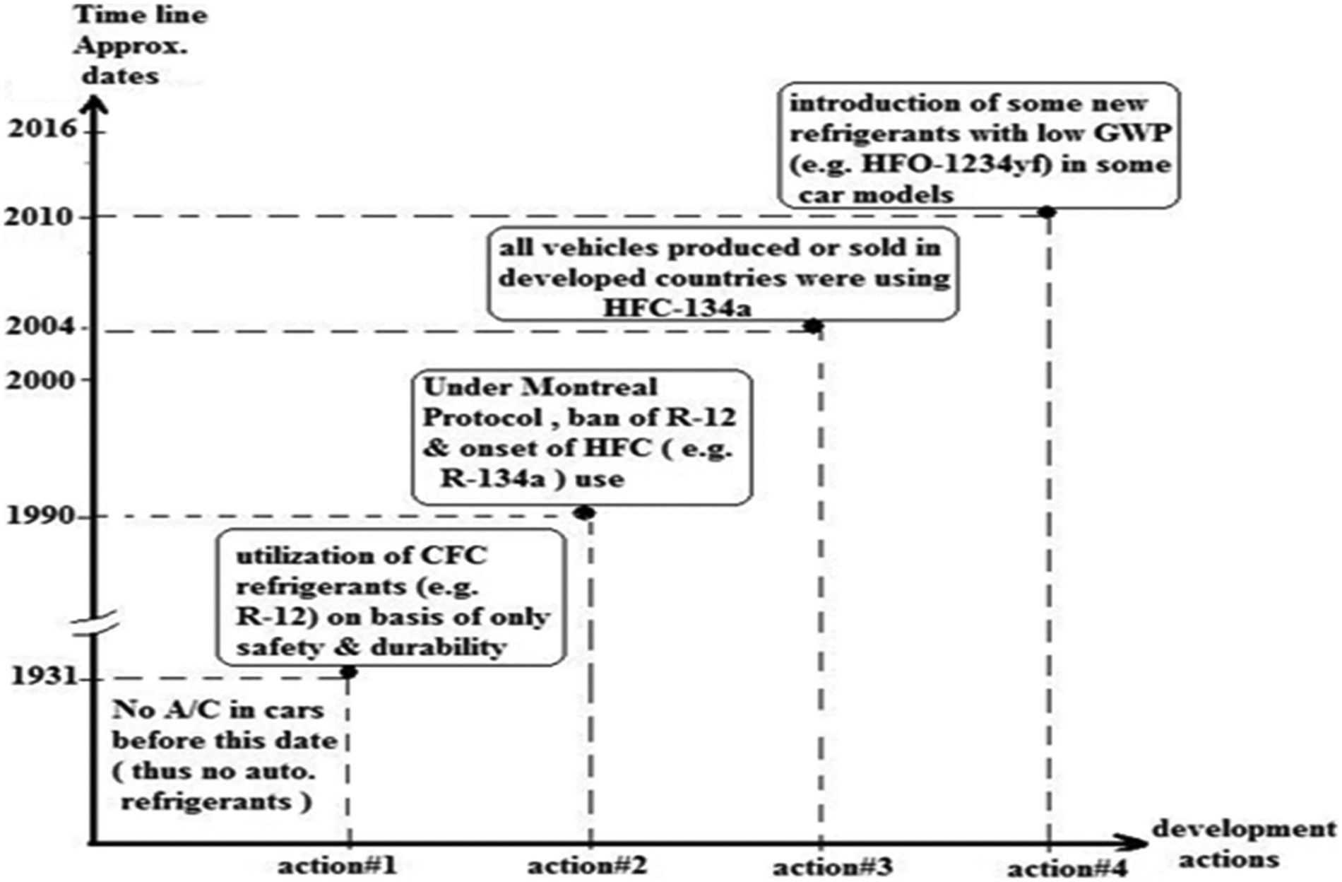
Development progression of automotive A/C refrigerants.
Although the new set of refrigerants was not harmful to the Earth’s ozone shield, it had to comply with global warming potential (GWP) condition which has become an essential environmental issue. According to European Union F-gas regulation, the GWP of any refrigerant must be equal or less than 150. Therefore, R-134a does not fulfill this criterion because its GWP is equal to 1300.
Consequently, deep concern for transitioning to low-GWP alternative refrigerants has spurred on considerable research effort and a third category of automotive refrigerants is developed. A number of candidates such as (DP-1, R-152a, R-744, and HFO-1234yf) are suggested to replace R-134a, but the candidature of CO2 (which is R-744) and HFO-1234yf has more potential.10,11 Indeed some auto makers have started the introduction of these refrigerants in special models of their cars. A technical assessment of alternatives to R-134a has been presented in a number of studies.9,12,13 Also the evaluation of the alternatives HFO-1234yf and R-152a has been performed by some investigators14,15 who have found that, with small modifications on the AC systems of current automobiles, the two previous refrigerants can replace R-134a.
For the candidate R-744, another study 16 has explained the important trends and characteristics in the development of CO2 technology, and it is concluded that some barriers have to be overcome before its commercialization. Based on the previous studies, the relative merits as well as the remaining problems to be solved for the above-mentioned future refrigerants are included in Table 1. Therefore, further work is still required to overcome many obstacles for commercial production and widespread utilization of the previous alternative refrigerants.
Relative merits and remaining problems for the most attractive alternative refrigerants.
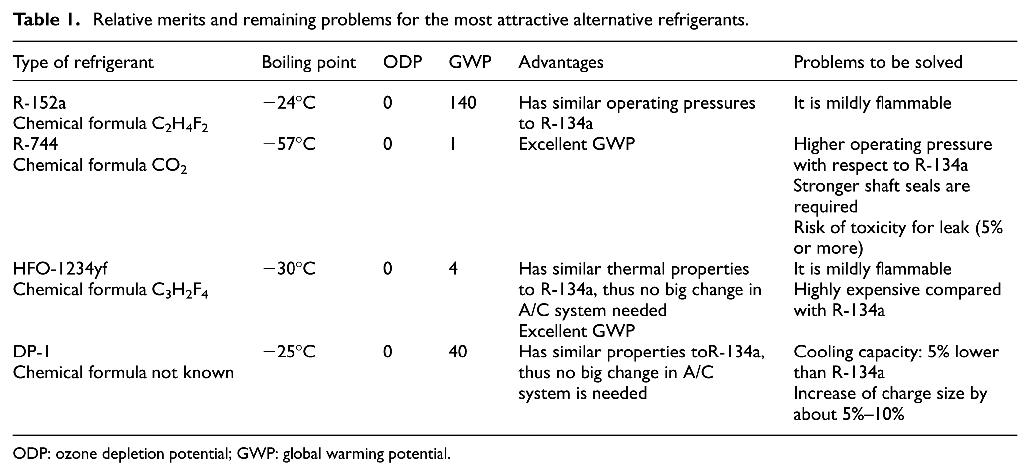
ODP: ozone depletion potential; GWP: global warming potential.
Developments related to the compressor
The compressor, which is the heart of the system, compresses the refrigerant sufficiently to raise its temperature above the ambient one and forces heat to transfer out of the condenser. Therefore, considerable research efforts have been carried out to develop a better successor of this A/C component. The compressor improvements can be divided as follows.
Design improvements
The primitive design of A/C compressor was of reciprocating piston and crank type. The piston(s) is connected to a crankshaft which is rotated by an engine pulley. The arrangements were in-line or V-shape. 4 This initial design has been discontinued due to its heavy weight and poor performance. To solve these problems, many new designs have been developed but the most successful ones are as follows.
Swash plate design
The first generation of this design is a reciprocating axial piston type which is characterized by a swash plate and fixed capacity, whereas the second generation has a design that enables the compressor to vary its capacity. This improved type of compressors still dominates the automotive A/C market because its technology is mature and its reliability is high.
Rotating van design
It is mainly characterized by its compactness, quietness, and low frictional losses. Also it produces the greatest cooling capacity per unit mass of the compressor.
Rotating scroll design
It has begun to spread out in the market because of its distinguished aspects such as quietness, weight lightness, and ability to reach 100% volumetric efficiency. The most common compressor designs that are used in automotive A/C systems are included in the classification diagram of Figure 3.

Design categories of automotive A/C compressors.
Regarding the development progression of the three designs that we have mentioned above, the various types and the approximated dates of eminent developments 17 are shown in Figure 4.
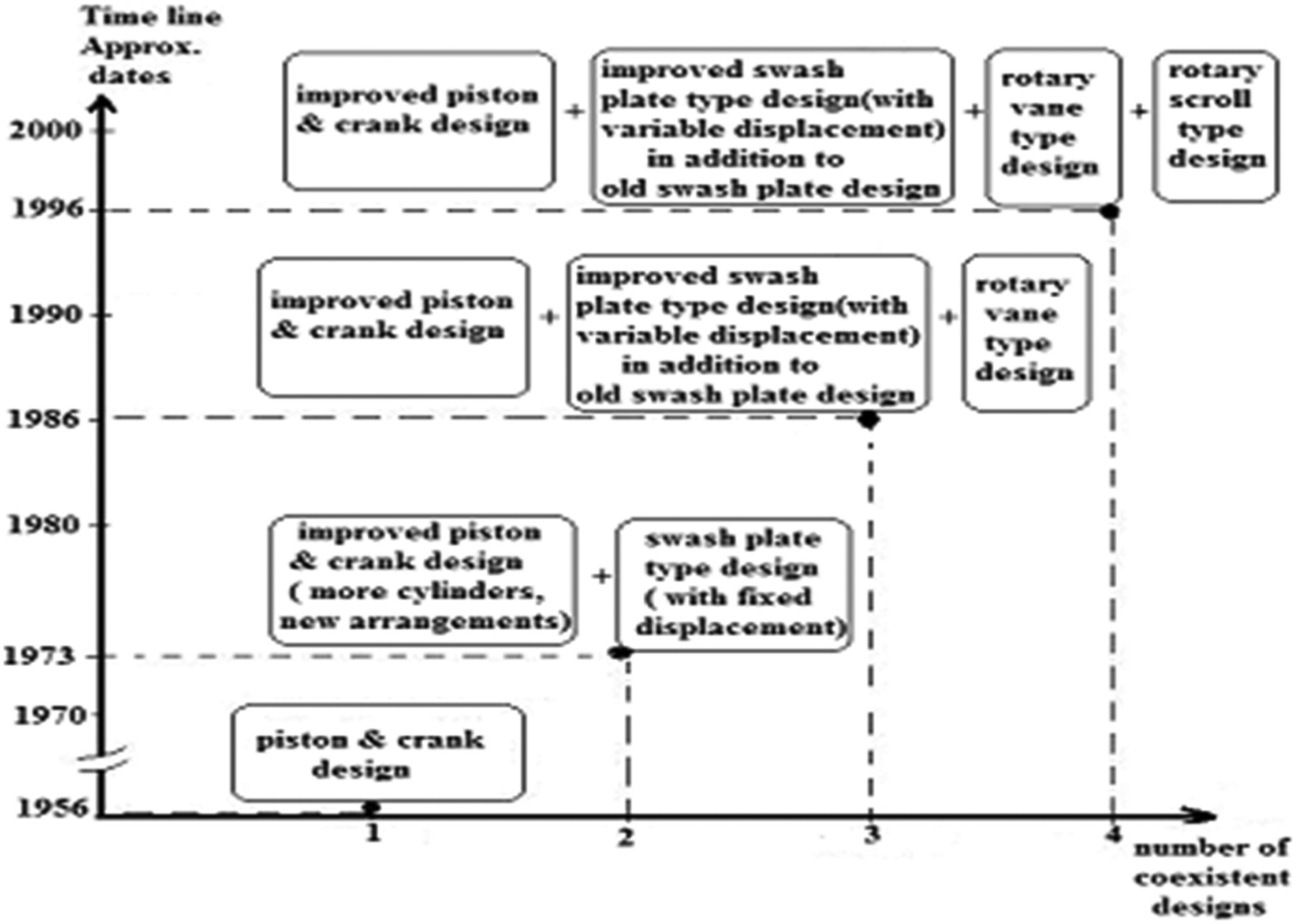
Development progression of different designs for automotive A/C compressor.
Also it has to emphasize that each new design was developed to satisfy new attributes which were not performed by the previous ones. Finally, it is important to mention that the development of hybrid cars has introduced a new type of compressors called hybrid compressor. This terminology is actually related to the compressor driving means (engine belt or electric motor) not to the compressor itself.
The increase in number of attributes required for new compressor design is illustrated in Figure 5.

Increase in the number of required attributes for newer designs as A/C system evolved.
Despite the benefits achieved by the three eminent developed designs (reciprocating swash plate type, rotary vane type, and rotary scroll type), there is still some design limitations. The important studies that have been conducted to address these limitations and improve each type of the above compressors are discussed below:
For the compressor with swash plate type design, it is noticed that one of its design limitations is the leakage through the valves. A group of researchers 18 have studied this problem and investigated the effect of the valve assembly on the efficiency of the compressor. According to the results obtained from a developed new design of the suction valve, the compressor performance has been improved and the coefficient of performance has increased by 12.7%. Also in another study, 19 a model for a fixed displacement swash plate compressor has been developed and an established method can be used to predict the volumetric efficiency and power of compressor. Furthermore, the investigators have used experimental data to validate the model and indicated that the method is very helpful for designers at early design stages. To compare the performances of fixed and variable capacity compressors, another team of investigators 20 have carried out a research work for these two types and found that the variable capacity compressor has usually a higher coefficient of performance (COP). Also an important study 21 has been performed for this type of compressors but with variable speed. The author has used an experimental analysis to determine the effects of compressor speed and condensing temperature on the thermal characteristics of automotive A/C. Furthermore, the researcher has extended the investigation to cover more alternatives of the current refrigerant R-134a.
Regarding the compressor with rotary vane design, leakage and friction losses associated with the contact between vane tips and inner surface of other components are two main design problems of this type of compressors. Therefore, a number of studies have been carried out to improve its design. In this context, a simulation model has been developed for rotary vane compressors, 22 and it is found that losses produced by leakage and vane tips friction are the dominant factor influencing the cooling capacity of the compressor. Also some improvement means (e.g. the reduction of the pressure in papilionaceous oil chamber) have been presented. Another team of researchers 23 have analyzed the forces that act on vanes using a numerical model and reported how these forces vary. They found for example that the contact force between vanes ant rotor in compression chamber become maximum near the discharge starting. Another research effort is conducted 24 to study a novel rotary compressor named “swing vane compressor.” The previous investigation has shown that this type of compressor has a number of characteristics which are better than their corresponding ones in a sliding vane compressor.
One more design limitation which affects both of the previous compressor designs (reciprocating swash plate type and rotary vane type) is noise and vibration. An investigation 25 has pointed out that the important causes of noise for swash plate type are the reciprocating frequency, number of pistons, valve dynamics, and acoustical and structural resonances. Whereas the noise in rotary types is mainly due to rotational frequency and multiples, numbers of rotating elements, and flow capacity. The researcher also indicated that some measures (e.g. use of dumping materials) can be applied to reduce the noise in these compressors.
3. Concerning the compressor with scroll type design, leakage and non optimization of design are still two main limitations that prevent the design as well as performance improvement. For this purpose, a simulation model is developed 26 to predict the performance of this important component and optimize its design. Also the effects of different losses such as leakage loss and mechanical loss on power consumption and how the efficiency improves, especially at high speeds, are investigated through the development of a prototype CO2 scroll compressor by Mitsubishi Heavy Industries. 27 According to the company findings, application of tip contact mechanism and thrust rolling bearing technology can reduce the above-mentioned losses. Finally, it is important to mention that CO2 is among the most promising future refrigerants because of its positive impact on environment. Another team of researchers 28 has studied the internal leakage and proposed an axial-compliant mechanism to solve that problem.
Noise is another design limitation, an essential study 29 has presented a number of solutions to prevent the possible causes of noise which come from the compressor (e.g. enlarging the shaft around 15 cm).
Finally, based on many studies30–33 and for comparison purpose, the important distinguishing data for each type of compressors are presented in Table 2.
Important information for compressors used in automotive A/C systems.

COP: coefficient of performance.
For the market share of each compressor type, Figure 6 shows the shares of the three world spread types.
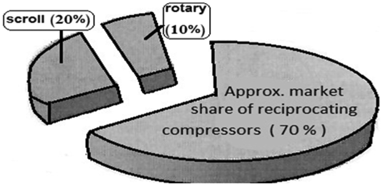
Market shares of auto A/C compressors.
Control improvements
Before 1985, all A/C compressors are of fixed displacement type. For that early generation, the system control was performed by switching the compressor on and off through an electro-mechanical clutch. As A/C systems were introduced in small size cars, this cycling clutch type of control has caused problems because of its sudden increase in engine load. To overcome these problems, internally controlled compressors have been developed. In this type of control, the compressor contains a number of axially oriented pistons which are driven by a variable-angle swash plate. A control valve changes the angle and produces an automatic adjustment of the compressor displacement that meets the automotive A/C demand. This development has made A/C system operation more quiet and with less energy consumption. To improve the compressor performance more, an electronic (external) control of the compressor has been introduced about 15 years ago. This new type of control consists of a control unit that changes the compressor displacement using inputs from many sensors such as temperature sensors of evaporator and air as well as the refrigerant pressure sensor. Certainly, the electronic systems can perform the control better as long as their sensors work perfectly. The previous types of control and the approximated dates of their eminent developments34,35 are shown in Figure 7.

Development progression of different control types for automotive A/C compressor.
In the last two types of compressor control, valves play an essential role in the process; consequently, many studies are conducted for improving their performance. One of the investigators 36 has developed a performance simulation program that can be executed to find out the most suitable stopper height of suction valve for swash plate angle controllability.
Weight and size improvements
Expansion of small size cars for the sake of energy saving and environment protection has put more limitation on installation space of automotive air-condition system. Therefore, considerable research efforts have been spent to reduce the size and weight of each component, including the compressor. Weight and size improvements are due to many factors, especially developments of tighter seals, lightweight materials (e.g. use of composites for pistons and plastic for pulleys), novel designs (e.g. clutch-less compressors), electronic monitoring (e.g. external compressor control), and application of computer-aided engineering to optimize dimensions of each component (e.g. use of flow analysis and shape optimization software).
To realize the extent to which the compressor weight has been reduced since 1950s, it is pointed out 5 that some models of the compressors, produced at that time, weighed nearly 27 kg. Whereas the average weight of today compressors is 5.5 kg. However, despite the big reduction achieved in the compressor weight and size, research efforts are continuous to develop lighter and smaller compressors. Many studies have been conducted about scroll compressors which are more attractive to be used in the future. In this regard, a new scroll compressor model with an improved efficiency and size reduction of 33% and 13%, respectively, has been developed. 37 Now let us move to the investigation of the two important heat exchangers used in automotive A/C systems (the condensers and evaporators). Figure 8 shows their classification on the construction basis.

Classification of heat exchangers used in automotive air-conditioning systems.
Concerning the improvements of condensers and evaporators, they are explained in the following order.
Developments related to the condenser
The condenser in A/C system acts as a heat exchanger and it transfers the heat loaded in the refrigerant to the surroundings. The severe conditions, imposed on automotive air-conditioners, imply that the condenser design must provide high efficiency and compactness for this important element. Therefore, A/C condensers have experienced considerable development during the last 50 years. Older condensers have a serpentine design, whereas newer ones have a parallel flow design. The condenser improvements can be divided as follows.
Design improvements
The design of earliest style of condensers (made of copper and composed of series of straight finned tubes with ends connected together by loops) has been significantly improved as many studies have been indicated. One of the studies 38 has presented a diagram that shows how the condenser efficiency has improved with the design evolution (1980–2010) from the serpentine type, passing by the multi-flow type, to the sub-cool type. Another one 39 has included a simulation model with a new sub-cool control and found that it has more energy-saving benefits compared to a conventional control design. The improvement gained in modern condensers performance is due to the following factors: using the aluminum (instead of copper) in tubes and fins manufacturing, increasing the number of fins per meter, and changing the condenser design as well as structure such that refrigerant flow allows better heat removal (better cooling). Consequently, the developed condensers have changed from the tube and fin style to the integral parallel flow/receiver–dryer style passing by serpentine and parallel flow types.
An important design limitation that can affect the condenser performance is its fouling. This drawback is investigated through the development of different simulation models. 40 The findings have shown that the fouling effects are severest for the refrigerant R1234yf with respect to R-134a and R1234ze. Thus, as alternative for R-134a, R1234ze is better.
Also blockage of micro-channels and repair problems of the condenser are two more design limitations that should be overcome.
Weight and size improvements
Wide spread of small size cars has enhanced research for developing more efficient and smaller condensers that can fit in the reduced frontal space of engine compartment. Using parallel flow design and aluminum alloy in building the new condensers has reduced their weight and size and improved their efficiency. In this context, a new type of condensers 41 has been developed, and it is smaller by 30% in size and lighter by 20% in weight with respect to previous models. Indeed, the application of the new design for tubes and fins and use of smaller sizes and thicknesses for the previous components have considerably improved the condenser performance. In an important performance analysis 42 for an A/C condenser and based on material and parametric design optimization, it is found that the use of a fin thickness of 1 mm and fin material aluminum alloy Al99 for the designed condenser gives better results. For the different aspects of each type of the automotive A/C condensers, a number of studies43,44 have included such valuable information and Table 3 presents the most important ones.
Important information for condensers used in automotive A/C systems.

Developments related to the evaporator
The evaporator function is to cool the inside of the vehicle by removing heat from warm air passing through its fins and transferring it to the refrigerant for boiling. The evaporator design is similar to that of a condenser. As for condenser developments (which enabled the passage from tube-fin and serpentine types to parallel flow type), evaporators have also undergone similar changes which led to the production of a newer type (drawn cup evaporators) besides the old ones (serpentine tube and corrugated fin types). In this regard, a comprehensive investigation 18 has indicated that several evaporator designs were developed between 1954 and 1980 and most of them had a ribbed plate and corrugated split bump lower fin design. Also, they were characterized by deep core and single-pass flow.
By the end of the 1980s, the previous core style was largely replaced by the plate–fin evaporator type. Later on, the U-channel single-tank vertical tube plate design was introduced to solve the problem of condensate drainage present in the previous evaporator types. Also the effects of different design parameters on the evaporator cooling capacity have be examined in another study. 45 According to the author simulation results, as the length of refrigerant channels increases an improvement of 19% in cooling capacity can be reached. In addition to the design limitation mentioned for the condenser, another design limitation that often happens in the evaporator is frosting and a group of investigators 46 have developed a mathematical model to find out the causes of this problem. Also they have used a test system to validate it, and their results have shown that higher air temperature at the condenser’s inlet can produce this problem of frosting.
Developments related to refrigerant controller
It regulates the amount of liquid refrigerant flowing through the evaporator and contains mainly an orifice tube or expansion valve. Through these devices (the orifice tube or expansion valve), the control takes place allowing the refrigerant to expand and the pressure to be lowered before the liquid refrigerant enters the evaporator. It is important to mention that orifice tubes have been developed before thermostatic expansion valves and their first generation were of fixed orifice. After that their performance has been improved using a variable orifice in them. Also thermostatic expansion valves are improved later on to become electronically controlled (electronic expansion valves (EEVs)). The choice of an expansion device that satisfies both cost and performance constraints for A/C systems with alternative refrigerants for R-134a (e.g. R-744) is still an open issue. In this context, an important study 47 has investigated different designs with a controllable expansion valve and a two-stage bypass orifice for a prototype of a R-744 automotive system. It is found that the controllable valve increases the COP by 15% better than the two-stage valve. Also a comparative study 48 between capillary tube, constant expansion valve, and thermostatic expansion valve has found that the last device offers maximum efficiency over a wide temperature and load range. Chocking flow in expansion valves has an important effect on their performance. A research team 49 has developed a model to investigate the chocking flow characteristics in EEVs and the investigators have found that the range of relative deviation between results predicted by their model and the experimental data presented in literature is from −5% to 6%. Another study 50 has treated the influence of the operating characteristics of an EEV on the operational stability of an A/C system, and it is found that the EEV–evaporator control loop becomes unstable when there is a larger proportional or integral gain.
Developments related to modeling methods of automobile A/C systems
One of the challenges that automotive air-conditioners face is the reduction of their energy consumption without decreasing the system performance or losing the quality of the thermal conditions inside the vehicle cabin. The development of effective models for A/C systems is one of the strategy components applied to overcome this problem. In fact, modeling of these systems, with its involvement of various software tools, is very helpful in designing highly efficient A/C systems.
Over the progression stages of A/C systems, different types of modeling approaches have been developed. Due to many factors (e.g. computer evolution), the early simple models of A/C systems were evolved to become more advanced with varying degree of complexity and efficiency. Considerable research efforts have been spent to produce a large number of modeling approaches for automotive A/C systems. These approaches can be classified to three categories. 51
Physical-based modeling approach
In this category, modeling of a system (or its components) is based on detailed physical relations for the sake of predicting the system performance.
This type of approach is characterized by its good capability of generalization, but it suffers from low accuracy.
Data-driven modeling approach
In this category, modeling of a system is based on the employment of its performance data and the application of some techniques (e.g. statistical regression) to predict the system performance. The approachability for generalization is very limited, but its accuracy is higher compared with the physical-based modeling approach.
Hybrid modeling approach
In this category, the physical-based modeling approach is applied to obtain the fundamental structure of a model, whereas the model parameters are estimated through some developed algorithms which are based on system data.
This approach type tries to have better characteristics by combining the two previous modeling approaches.
Based on the overview of a great deal of automotive A/C modeling literature, most of the models are physical-based approaches with incorporation of varying degrees of empirical parameters. The models can be devoted for the whole A/C system or to one to its components:
Models developed for the whole A/C system. In an important study, 52 a model is developed for steady-state and transient operational modes of a mobile A/C system. The model has been validated based on steady-state and transient data which were collected from a test facility. Also it is found that the model prediction for most of the system parameters was within ±15% in steady-state mode, and its prediction to the behavior of the city driving cycle as well as other transient component modes was good. Another comprehensive model to estimate a vehicle A/C loads has been reported in an SAE paper. 53 The model has applied the heat balance method, as well as the lumped-body approach. According to the developers, the model can predict the pattern of upcoming changes in the comfort level for producing reduction in the overall AC power consumption. A third model has been presented in the study. 54 It is found that the predicted model results had a deviation from the experimental ones of about 20%.
Models developed for the individual A/C system components. In this context, a model has been developed in the study 55 for predicting the steady-state performance of a reciprocating automotive A/C compressor. The investigators have reported that the model is based on experimental data and it can predict the discharge refrigerant enthalpy, the required compressor power, and the refrigerant mass flow rate with reasonable accuracy. Another model has been developed by FS Yi et al. 56 for a scroll compressor of an automotive A/C system. According to the researchers, all processes that the refrigerant experiences through the compressor are considered in the modeling, which enables the model to predict the compressor performance and optimize the design of future scroll compressors.
Concerning the modeling of A/C condensers and evaporators, in the study by Saiz Jabardo and Mamani, 57 a developed model for micro-channel/louvered fin condensers has been presented. It is indicated that for the chosen tested condenser, the model results compare very well with the experimental data within an acceptable range of deviations. In another important study, 58 a model for automotive A/C evaporators has been reported. It is mentioned that the model can predict the evaporator performance within a 5% range.
From the previous models, it can be concluded that the models’ accuracy needs more improvement. Therefore, more research work is required.
Developments related to international standard test procedure for additional fuel consumption of automotive A/C use
Fuel consumption is an important operational parameter to assess a vehicle performance. This indicator is usually measured through laboratory tests. During these tests, the vehicle driving is performed on a chassis dynamometer (which simulates the different resistances that oppose the vehicle on roads) to follow a predefined test cycle. Also all required conditions for test running must comply with the specified test procedure.
Over the past half century, many drive cycles and test procedures were developed. The most common ones (for light-duty vehicles) are as follows:
Test procedures based on the European test cycle (NEDC);
Test procedures based on the American test cycle (FTP-75);
Test procedures based on the Japanese test cycle (JC08).
Unfortunately, up to recent years, the additional fuel consumption, which is due to automotive A/C use, was not taken into account in test procedures of vehicle energy efficiency although its share can reach 30% of the overall fuel consumption. Therefore, it is very important to develop an international standard test procedure that considers the extra fuel consumption and emissions of A/C use. Also it has to be characterized by distinguished aspects that ensure its internationality and standardization such as high accuracy and repeatability, inclusion of all necessary parameters, and clear discrimination of different systems.
To achieve this goal, many test procedures have been developed, but they still have some drawbacks. An important test cycle and procedure is presented by M Tutuianu et al. 59 According to the authors, this worldwide harmonized light-duty test cycle (WLTC) is based on “real world” driving data from five different regions: EU, USA, India, Korea, and Japan. It covers a wide range of vehicle categories (M1, N1 and M2 vehicles, various engine capacities, power-to-mass ratios, manufacturers, etc.). Also it considers different road types (urban, rural, motorway) and driving conditions (peak, off-peak, weekend). From the stated regions, the test cycle is limited in regions representation (e.g. Gulf area which has become very hot, dusty, and humid is not included). Another interesting study about test procedure for measuring the percentage of A/C fuel consumption is included in progress update report. 60 Although the test has considered many parameters, again it is limited to Europe climates (which weakens its repeatability). A third test procedure for assessing the additional fuel consumption of A/C use has been presented by RJ Vermeulen et al., 61 but the investigators have found that the results show limited repeatability and reproducibility in addition to other drawbacks.
Other test procedures for evaluating A/C emissions and A/C pull-down period have been reported in the studies,62,63 but they still need more improvement.
In order to ensure that all tests are performed in a comparable way and have worldwide aspects on one hand, and to reduce, as much as possible, the difference between the results of laboratory tests and the real-world tests on the other hand, a road map was presented in 2009 for developing a WLTC and a worldwide harmonized light-duty test procedure (WLTP). 64 This road map includes three phases, and the second phase (2014–2018) addresses among other issues the energy efficiency of automotive A/C systems. However, more research work is needed to develop worldwide harmonized test procedures that have international aspects regarding repeatability, reproducibility, and so on.
Conclusion
Invention of automotive air-conditioners has transformed the vehicle cabins from oven conditions to comfortable ones during the traveling in hot seasons. However, this vital system was initially very bulky, non efficient, and without control, then it has experienced many advances that this article has highlighted. First, brief historical developments of the automotive (A/C) system are presented. After that the evolution of the automotive refrigerant since 1930s up to the future candidates for R-134a replacement is provided.
Because of severe restrictions related to safety, energy efficiency, and environment protection, only few refrigerants meet the imposed attributes such as zero ODP and low GWP. According to research findings, CO2 and R1234yf have a big potential to be the future refrigerants.
For the major components of a standard vehicular (A/C) system, the development progression of each of them is outlined. The improvement achieved for each element is mainly due to the advances in the design, control, and weight. The compressor (heart of the system) has changed from the early piston and crank design to several new types, and the future trends indicate that the scroll compressor is the most promising in the future. Concerning the condenser, the parallel flow, micro-channel, and integrated receiver condensers have significant advantages compared with the primitive finned tube ones. Consequently, they have more potential for the dominant use in the future. Similar aspects are required for next-generation evaporators. For the control evolution, the future trends in this domain show that the advanced electronic type is the most attractive because it provides better improvement for the performance of the A/C system. Despite the dominant improvements made, the present conventional A/C system still has some weaknesses such as high energy consumption, pollution, and performance decrease at certain speeds. Models developed for A/C systems still have some shortcomings (e.g. low accuracy). Also, the test procedures for A/C system extra fuel consumption are still not worldwide in all aspects. Therefore, more efforts should be made to solve these problems.
Footnotes
Academic Editor: Bo Yu
Declaration of conflicting interests
The author(s) declared no potential conflicts of interest with respect to the research, authorship, and/or publication of this article.
Funding
The author(s) disclosed receipt of the following financial support for the research, authorship, and/or publication of this article: The authors would like to acknowledge the funding and support from the National Science, Technology and Innovation Plan (NSTP), Qassim University, Saudi Arabia, through the research project No. 12-ENV2330-09.