
Abstract
The condensing and evaporating characteristics of an auto-refrigerating cascade cycle employing ternary zeotropic mixture R600a/R23/R14 are studied in this article. When the outlet temperature of condenser is 300 K, the composition ratio of R600a/R23/R14 in liquid mixture is 78.04/12.62/9.34, respectively. In the liquid mixture, the R600a is the dominating component. The separation mass fraction of R23 by phase separators I and II is 12.62% and 30.27%, respectively; 78.04% refrigerant R600a can be separated by phase separator I, and 9.34% refrigerant R14 is liquid. In evaporator, the composition ratio of R600a occupies 6.31%, while the low-boiling-point refrigerant R14 accounts for 45.64%. The changing of composition ratio could significantly influence the cooling loads while had a little influence on the changing of the evaporating temperature. The maximum cooling load is 85 and 50 W for composition 35/35/30 and composition 35/30/35, respectively, and the maximum coefficients of performance are 14.4% and 8.5%, respectively.
Keywords
Introduction
Mixed refrigerant Joule–Thomson cryocoolers have unique advantages for small refrigeration systems for 70–230 K applications. 1 They are widely used in the fields of gas chillers, infrared sensors, semiconductor fabrication systems, liquefaction plants, and cryosurgery devices. 2 The system requires only one compressor without moving equipment at the low-temperature part. Two types of mixed refrigerant Joule–Thomson cryocoolers have been developed and can achieve lower than 230 K refrigeration requirement with relatively high efficiency. Among them, one is known as the Linde–Hampson refrigerator (LHR) and the other is the auto-refrigerating cascade (ARC) system, which is also referenced as Kleemenko’s cycle. The ARC system includes phase separators, which removes the liquid from the stream at various junctions along the high-pressure channel, throttle valves, and corresponding heat exchangers. Since the liquid is enriched with higher boiling point components, the removal of some parts means altering the composition of the mixture. In contrast to the LHR, which maintains a constant composition, the ARC cycle has a composition gradient along the heat exchangers.3,4
Many theoretical and experimental studies on zeotropic mixture condensing characteristics of ARC system have been conducted in recent years. For instance, Ghorbani et al. 5 studied the liquefied refrigerant by passing through the condenser. Condensed refrigerant was entered to an expansion valve, and its pressure was decreased to the operation pressure of evaporator. By comparing the ethane recovery, Mehrpooya et al. 6 investigated that ethane recovery in the self-refrigeration process was higher. Increasing integration of the process decreases the operating costs and increases the natural gas liquid (NGL) recovery. Asgari et al. 7 found that the condenser inlet temperature growth improves the total avoidable exergy destruction within 88.19%, the total avoidable investment cost rate increases by about 126.92% and 3.68% as compressor inlet mass and refrigerator evaporator inlet temperature rise, respectively, and the increment of refrigerator evaporator inlet temperature shows a positive effect on the total avoidable exergy destruction cost rate. Boyaghchi and Asgari 8 chose compressor mass flow rate, condenser inlet temperature, refrigeration evaporator inlet temperature, and freezer evaporator inlet temperature as substantial design parameters to evaluate the performance of both proposed systems.
Although there are many researches about condensing and evaporating characteristics of ARC system, the liquid and vapor composition of zeotropic mixture in circular double-tube condenser has not been reported. The theoretical investigation of ARC circular for double-tube condenser could optimize the composition of multi-component mixture working in low-temperature ARC system. And this composition would influence the system performance of the ARC cryocooler.
In recent years, an increasing investigation of the evaporating characteristics and influential parameters on ARC system has been done. Among those, Missimer 9 presented a brief history of the mixtures for ARC systems. Moderate ARC systems had been successfully converted from the use of chlorofluorocarbons (CFCs) components to completely CFC-free refrigerant mixtures. Kim et al. 10 investigated the performance of an ARC system using zeotropic refrigerant mixtures of R744/R134a and R744/R290. One advantage of this system was the possibility of keeping the maximum system pressure by selecting appropriate refrigerant mixture composition. An ARC system for achieving ultra low temperature was also developed, though it has low coefficient of performance (COP) values. 11 Wang et al. 12 proposed a new approach, which was not only applicable for binary refrigerants, but also applicable for multi-component mixtures, to investigate the performance of a single-stage ARC operating with two vapor–liquid separators and environmentally friendly binary refrigerants.
The research of the optimism performance for ARC cycle cryocooler is still on the going. Transient cycle characteristics of condenser and evaporator are important performance characteristics for ARC systems. And no report on the cycle features of ARC systems employing ternary refrigerants of R600a/R23/R14 was published. This work aims to conduct a theoretical analysis at condenser and two-phase separators, as well as experimental comparison at evaporator of a ternary refrigerant R600a/R23/R14.
Condensing characteristics of zeotropic mixed refrigerant
A schematic diagram of a three-stage ARC system with bypass is displayed in Figure 1. This refrigerating plant has two phase separators. The high-pressure recuperating stream of the mixed vapor is interrupted by the phase separators, each one removing the entire liquid fraction that is enriched with the higher boiling point components. The liquid portion at each stage is throttled and mixed into the channel of the returning low-pressure stream. The remaining high-pressure vapor stream flows to the next phase separator. The phase separators alter the mixture composition because coexisting liquid and vapor of a multi-component refrigerant have different compositions. After being separated, the liquid is throttled and sent into the low-pressure returning stream part of the heat exchanger. At each stage, the liquid is separated from the remaining vapor flow and is then throttled by capillary and mixed with the returning vapor flow.

Schematic diagram of the ARC system.
As the performance of the refrigeration system is heavily influenced by the compositions of the ternary system, it is essential to identify an appropriate composition ratio. In the experiment, five different ratios of the refrigerant were examined, namely, 35/35/30, 35/30/35, 30/35/35, 30/30/40, and 35/25/40 for mixed refrigerant R600a, R23, and R14, where the numbers refer to the mass ratio of each refrigerant. According to the preliminary study, the composition of ternary refrigerants R600a/R23/R14 of three-stage ARC system should be 35/35/30; the analysis of condensing process is carried out based on this proportion. The suction and discharge pressure are 0.2 and 2.0 MPa, the ambient temperature is 300 K, the evaporating temperature is 180 K, and the cooling capacity is 60 W.
The condensing temperature decreases for zeotropic mixed refrigerant at constant pressure; the mass fraction in vapor and liquid changes with the condensing temperature. Table 1 presents the condensing characteristics calculated by software NIST refprop8.0; in Table 1, the condensing pressure is 2.0 MPa, and temperature reduces gradually from 380 K which is the compressor discharge temperature. When the temperature reduces to 300 K similar to the condenser outlet temperature, the vapor mass fraction is 0.72, and the condensed liquid mixture accounts for only about 28%. The high-pressure and high-temperature vapor mixture is condensed by cooling water, when the temperature reduces to 324.54 K. The mass fraction of R600a in liquid droplet is 86.55%, while R23 and R14 occupy 7.43% and 6.02%, respectively. With the decrease in cooling temperature, the vapor mixed refrigerant is condensed into liquid gradually. At the same time, the mass fraction of R23 and R14 in vapor mixed refrigerant increases and the mass fraction of R600a decreases gradually in condensed liquid mixture. The vapor mixed refrigerant is condensed into liquid totally when the cooling temperature reaches 249.49 K. In the finally condensed mixture droplet, R600a, R23, and R14 occupy 2.68%, 32.73%, and 64.59%, respectively, in mass fraction. In the final liquid mixed refrigerant, the mass fraction is 35%, 35%, and 30%, respectively, for R600a/R23/R14, which is completely consistent with the vapor composition before condensation.
Characteristics of mixed refrigerant at 2.0 MPa.

Figure 2 is the bubble point lines and dew point lines, respectively, for the condensing pressure 2.0 MPa and evaporating pressure 0.2 MPa when mixed refrigerant is R600a and R23. The vapor–liquid equilibrium relationship of two mixed refrigerants is shown in Figure 2. When the mixture is cooled, liquid begins to form at the dew point temperature, which does not complete until the temperature reaches the bubble point temperature. The temperature difference between the dew and bubble point lines is known as a temperature glide. The concentrations of the liquid and the vapor phase are never equal. This creates a temperature glide during phase change. The concentrations of the vapor and the liquid continuously change at phase change point. As it can be seen in Figure 2, the bubble and dew point line do not meet at any point.

Bubble and dew point temperature at 2.0 and 0.2 MPa.
The mixed refrigerant becomes high-temperature and high-pressure vapor after passing through the compressor, and then, it is cooled and condensed by condenser. Double-pipe condenser consists of two pipes or tubes, which are arranged in a way that one is inside the other. Water is piped through the inner tube, while the mixture flows through in an opposite direction in the space between the inner and outer tubes. With this arrangement, mixture is cooled not only by the inner tube water, but also by the natural air convection. Double-pipe condenser increases the heat transfer coefficient of mixed refrigerant and then reduces the cooling water flow. And the counter-flow arrangement gives the highest rate of heat transfer and reduces the required size. The mixture cooling section in condenser can be divided into cooling section and condensing section. In cooling section, the mass fractions of mixed refrigerant do not change for vapor mixture, and the temperature is reduced to the dew point from the outlet of compressor. The temperature is reduced continually from dew point to 300 K to condenser outlet temperature, and the mass fractions of vapor and liquid mixture change with the decrease in temperature. When the temperature is reduced to 324.54 K, mixture has liquid droplet precipitation, and the mass fractions of three kinds of vapor refrigerant gradually change, as is shown in Figure 3.

Vapor composition ratio of phase separator I.
The outlet temperature of condenser is always between 280 and 300 K, and the temperature of phase separator I is the same to the outlet temperature of condenser. The mass fraction of R600a in vapor mixture decreases monotonically from the beginning composition ratio 35% when the condensing temperature reduces. R600a is not fully condensed into liquid in the condenser, and the mass fraction of R600a in vapor mixture is 18.25% at 300 K. The mass fraction of R600a in vapor mixture has 9.8% at 280 K. Even if the vapor refrigerant R600a still has mass fraction 2.7% at the bubble point temperature 249.49 K, the vapor refrigerant R23 increases first and then decreases with the cut-down of condensing temperature. Because the condensing speeds of R600a are faster in the early stage, R23 and R14 condense less and its mass fraction in vapor mixture increases. Along with the further condensation, the amount of R600a which can be condensed is little, while the condensed amount of R23 increases gradually. R14 is a non-condensable gas compared to R600a and R23, and it occupies a very small proportion in the liquid, and the mass fraction in vapor mixture increases monotonically. R14 is one of the low-temperature refrigerants with stable performance, R23 is currently one of the best refrigerants at 200 K for cascade refrigeration systems, and R600a is the most commonly used refrigerant in household refrigerators. The mass fractions of phase separator I at temperature 290 K and pressure 2.0 MPa are 13.56%, 45.81%, and 40.63% for refrigerant R600a/R23/R14.
As is shown in Figure 4, the temperature of phase separator II is determined by outlet temperature of high-pressure channel of heat exchanger I, and it changes between 240 and 260 K. R600a is not fully condensed into liquid after flowing out of heat exchanger I. For example, the mass fraction of R600a in vapor mixture has 2.5% at 250 K, and the residual R600a still has 0.9% at bubble point temperature 233.93 K. With the gradual decrease in condensing temperature, R23 increases slightly in vapor mixture and then decreases slightly. R600a decreases quickly so that the mass fraction of R23 increases relatively in vapor mixture. With the further decrease in condensing temperature, R23 becomes the main condensed refrigerant, making the mass fraction of R23 decrease quickly in vapor mixture. Compared to R600a and R23, R14 is still the non-condensable gas. When the condensing temperature arrives at 260 K, turning points for vapor mass fraction of R23 and R14 exist. The condensing speed of R23 increases after this point, and the mass fraction of R23 decreases significantly, while the mass fraction of R14 increases significantly in vapor mixture.

Vapor composition ratio of phase separator II.
The mass fraction changes of vapor mixture through two phase separators are shown in Figure 5. In the abscissa, 1 is the mixture composition of condenser and 2 and 3 are vapor composition of phase separator I and phase separator II, respectively. Phase separator I cannot completely separate refrigerant R600a. The vapor mixture has 18.25% mass fraction of R600a after flowing out of phase separator I, and the vapor mixture still has 6.31% mass fraction of R600a after coming out of phase separator II. Only 30.27% mass fraction of R23 is removed by phase separator II, 12.62% is removed by phase separator I, and the rest R23 component is brought into evaporator. The proportion of mixed refrigerant R600a/R23/R14 in evaporator is 6.31/48.05/45.64, rather than pure refrigerant R14.
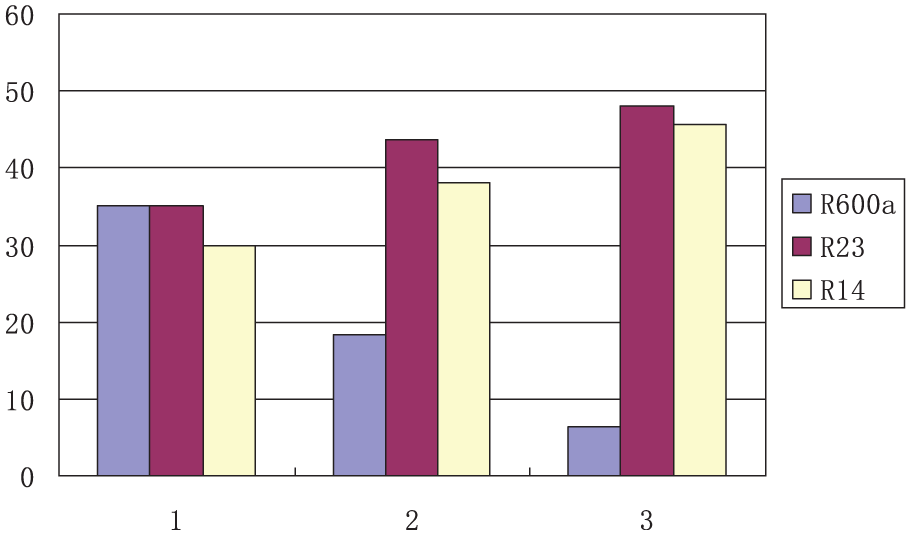
Mass fraction changes of mixture.
Evaporating characteristics of zeotropic mixed refrigerant
Experiment system
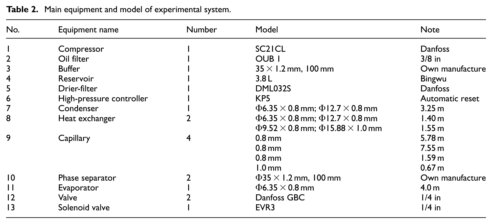
The ARC cycle shows a staging-like effect by changing the composition of the single pressurized stream of mixed vapor and liquid. The compressor is SC21CL of Danfoss; the suction and discharge pipe sizes are Φ9.52 × 0.8 mm and Φ6.35 × 0.8 mm, respectively. The compressor speed was calculated according to the nominal speed 2800 r/min and displacement 20.95 cm3. The discharge temperature is controlled within 390 K; otherwise, higher temperature can easily cause the lubricating oil decomposition, carbonization phenomena, and so on. As a result, the preliminary discharge temperature is determined as 380 K. The suction temperature is determined by the discharge temperature range and pressure ratio of the compressor. Compression process is usually assumed to be isentropic process (reversible adiabatic process), ignoring the heat exchange of compressor. The main equipment and model of experimental systems are listed in Table 2.
Main equipment and model of experimental system.
Temperature and pressure data were logged and processed in the data collection system through Data Acquisition Instrument Agilent 34970A, including real-time display, calculation, and control output print. There are 28 temperature measuring points’ layout along the pipeline in system and 2 pressure measuring points (shown in Figure 1). Copper–constantan T thermocouple (Chino of Japan) was used to measure the temperature. The measure accuracy is ±0.5 K and the diameter is 0.3 mm. They were made by DC welding method and determined by calibrating in thermostatic bath through level 2 standard thermometers. The temperature value of thermocouple could be read directly from 34970A, which has inner thermal resistor to perceive the environment temperature. The pressure sensors were NS-I1 (Shanghai Tianmu Automation Instrument Co., Ltd). The range of high- and low-pressure sensor measurement was 0–4.0 MPa (absolute pressure) and 0–2.0 MPa (absolute pressure). The supply power is 24VDC, and output signal is 4–20 mA (precision grade is 0.25 level). Pressure measured was the compressor suction and discharge pressure.
The main cryogenic heat exchangers are concentrated in cryostat, including two heat exchangers, two phase separators, three capillaries, an evaporator, and the connecting pipeline. The cryostat is a stainless steel barrel with a diameter of 350 mm and a height of 750 mm. Each part of inner cryostat was polished precisely in order to reduce the radiation heat transfer. Heat preservation processing was needed as the whole cryostat was in the low-temperature condition. After the system installment was completed, three important processes such as leakage testing, vacuum pumping, and charging refrigerant have been done, and then, the system debugging could be carried on.
The examination method mainly was the 2.2 MPa dry nitrogen for high-pressure holding and the low vacuum for vacuum holding guaranteeing the strict tightness of inner laboratory system. The suction and discharge pressure, the suction and discharge temperature, frosting condition on the copper pipeline, and the power of compressor were observed at any time, and these parameters reflect the compressor running state directly and the security condition of compressor. Observing the change of system parameters at the starting up process, the important parameters mainly were the temperature and pressure of compressor and the evaporating temperature. The initial stage of experiment mainly aimed at the debugging of component and composition for mixture; refrigerants R600a, R23, and R14 charged to the system were not enough for recording the charging component and composition separately. According to the running situation, the amount of mixed refrigerant R600a, R23, and R14 would increase gradually, and then, the charge of refrigerant would stop while the discharge pressure was about 2.2 MPa. The refrigerant charge method adopted the weight filling method; the charge quantity was in the range of 340–380 g, and 360 g was the optimal refrigerant charge quantity. Experimental ambient temperature was 285–290 K in the spring of Shanghai. Figure 6 shows a snapshot of the experiment system.

Photograph of the experiment system.
Cooling process of composition 35/30/35 and 35/35/30
The evaporating temperature of different cold loads for mixture R600a/R23/R14 at composition 35/30/35 is shown in Figure 7. The trends of evaporating temperature were generally similar to the increase in cold load, and the cooling process can be divided into three parts: rapid cooling, fluctuation, and constant. The difference in the five cold loads has two aspects: (1) Different cooling speed—the colder the load, the slower the cooling rate: at 25 min, it could be reduced to the lowest temperature at zero loads, 40 min at 30 W, 60 min at 40 W, and 70 min at 50 W. (2) Different final evaporating temperature. The higher the cooling load, the higher the evaporating temperature: the final evaporating temperature at zero load, 30 W, and 40 W was about 175 K, and at 50 W, it was near 188 K. And the evaporating temperature did not reach to the lowest value after 90 min at the cold load 60 W. The mixed refrigerant, which mainly relies on refrigerant latent heat in the evaporator, absorbs heat from the surrounding environment constantly. The colder load needs more evaporating transition mixture. The cooling capacity of the evaporator is mainly with the flow of low-temperature liquid mixture, and the liquid flow rate is greater and the cooling capacity is larger, and vice versa.
Evaporating temperature of composition 35/30/35.
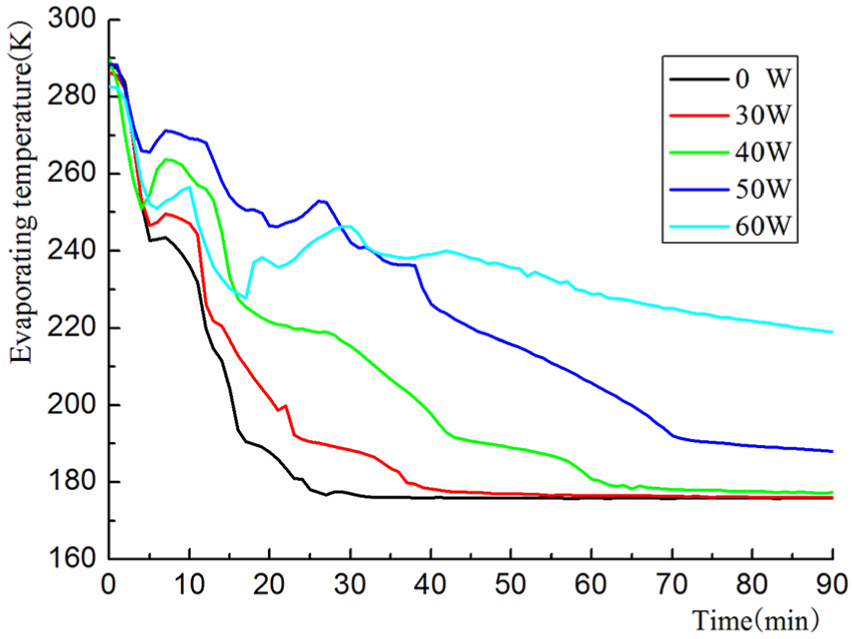
The cooling capacity of evaporator was initially identified as 60 W, and the evaporating temperature was identified as 180 K. Figure 8 is the evaporating temperature change in different cold loads for mixture R600a/R23/R14 at composition 35/35/30. Compared with composition 35/30/35, the changing trends of evaporating temperature have the same trend; the cooling rate of evaporator decreases with the increase in loads. The stable equilibrium temperature was 175 K; also, the change trends of evaporating temperature differ, and the cooling rate was not the same at equal cooling loads of evaporator. For example, when the cooling capacity of evaporator was 60 W, the evaporating temperature of composition 35/35/30 reduced to 175 K after 60 min, but the evaporating temperature of composition 35/30/35 only reduced to 220 K after 90 min. The evaporating temperatures of composition 35/35/30 reduced to the lowest temperature after 20 min at zero loads, while this process will cost about 80 min when the cooling capacity of evaporator was 80 W and 85 W, and the evaporating temperature did not reach the lowest temperature after 120 min at the cold load of 90 W.

Evaporating temperature of composition 35/35/30.
Refrigerating capacity of compositions 35/30/35 and 35/35/30
The evaporating process of vapor-liquid pure refrigerant in evaporator is a constant pressure and constant temperature process. The evaporating temperature is the saturated temperature corresponding to the saturated pressure. The pressure of mixed refrigerant in evaporator is constant, but the evaporating temperature, the vapor, and liquid composition change continuously. Figure 9 shows the evaporating temperature of different cold loads with different evaporator lengths for mixture R600a/R23/R14 at composition 35/30/35. There were five temperature measuring points evenly installed along the length of evaporator; the evaporating temperature and vapor-liquid component were changed with the flow of mixture in evaporator. The evaporating temperature changed little when the vapor-liquid mixture flowed into evaporator at the cooling load of 60 W, and the evaporating temperature increased faster passing through the one-fourth length of evaporator and ran up to 240 K at the outlet. The evaporating temperature of the cooling load 60 W was basically similar to pure refrigerant, because the cooling load was larger and mixture was evaporating faster. The evaporating temperature trends in other cooling load conditions were similar; the temperature of mixed refrigerant, which flowed into the evaporator, decreased first and then increased, and the lowest evaporating temperature 175 K could be achieved. Because the cooling loads were small, the pressure decreased when mixed refrigerant flowed into evaporator from capillary. The space of capillary was narrow, mixed refrigerant diffused rapidly when it flowed into the evaporator, and the temperature was reduced to about 10 K. With the absorbing of external heat by mixed refrigerant, the evaporating temperature increased constantly. The evaporating temperature increased from 1/4 to 1/2 length of evaporator because the vaporizing refrigerant was mainly R600a and R23 components, and a large number of R14 vaporized at the end of evaporating process, thus making the evaporating temperature relatively gentle.

Evaporating temperature of composition 35/30/35 along the length.
The mixture temperature increased from bubble point temperature to dew point temperature gradually along with the evaporating process continued, and there was a temperature slip for phase change of zeotropic mixture. The vapor-liquid mixture was flowing into the evaporator and absorbing heat, and bubbles would be formed when the tube wall temperature is higher than the bubble point temperature. The evaporating temperature of different cold loads along the length of evaporator for mixture R600a/R23/R14 at composition 35/35/30 is shown in Figure 10. Five temperature measuring points were evenly installed along the evaporator, and the evaporating temperature and vapor-liquid component changed with the flow of mixture in evaporator. The evaporating temperature was constant probably when the vapor-liquid mixture flowed into evaporator at the cold load of 90 W, and the evaporating temperature increased quite quickly when the fluid passed through a quarter of evaporator length. The evaporating temperatures of other loads were almost the same, and the temperature of mixed refrigerant in evaporator first decreased and then increased. Compared with Figure 9, the variations in evaporating temperature while the cooling load was 90 W were similar to those while the cooling load was 60 W at composition 35/30/35.

Evaporating temperature of composition 35/35/30 along the length.
According to Figure 10, the trends of evaporating temperature were slightly the same when the cold load was below 85 W, and the temperature difference was little. The evaporating temperature increased significantly when cold load was more than 85 W. So, the maximum cooling load could be considered as 85 W for composition 35/35/30, and the maximum cooling load could be considered as 50 W for composition 35/30/35 from Figure 9. According to the nominal power 590 W of Danfoss SC21CL compressor and the maximum cooling load, the maximum refrigeration coefficient COP was 14.4% for composition 35/35/30 and 8.5% for composition 35/30/35. The COP of ARC system depended on the cooling load at the constant compressor power conditions, while the cooling load was influenced by many factors. The mass flow rate of low-boiling-point refrigerant in evaporator should increase as far as possible under the mixed refrigerant component determined, reducing other component refrigerant and non-condensable gas. The more liquid mixed refrigerant, the more vaporized refrigerant, so the increase in the component of low-boiling-point refrigerant and the flow rate of liquid mixed refrigerant can improve the COP of ARC system.
Conclusion
The separation mass fraction of R23 by phase separator I and phase separator II is 12.62% and 30.27%, respectively. The rest of the R23 goes into the evaporator. Phase separator I can separate 78.04% high-boiling-point refrigerant R600a and 9.34% low-boiling-point refrigerant R14. The composition ratio of R600a in evaporator still occupies 6.31%. The low-boiling-point refrigerant R14 only accounts for 45.64%.
The final evaporating temperatures of zero load, 30 W, and 40 W for mixture R600a/R23/R14 at composition 35/35/30 and composition 35/30/35 were about 175 K. The composition ratio change could significantly influence the cooling load and just had a little effect on the lowest evaporating temperature. The maximum cooling load was 85 and 50 W for composition 35/35/30 and composition 35/30/35, respectively, and the maximum COP was 14.4% and 8.5%, respectively.
Footnotes
Handling Editor: Jiin-Yuh Jang
Declaration of conflicting interests
The author(s) declared no potential conflicts of interest with respect to the research, authorship, and/or publication of this article.
Funding
The author(s) disclosed receipt of the following financial support for the research, authorship, and/or publication of this article: This work is supported by the Science and Technology Program of Henan Province, China (172102410026).