
Abstract
Estimate of the hydrodynamic force exerting on the frog is a key factor in design of mechanical structure and control system. To research propulsion generation mechanism during frog swimming, computational fluid dynamics–based method was performed. From the propulsive force results, drag and lift components of hydrodynamic forces were decomposed in terms of the palm motion. The thrust in the aquatic swimming trial turned to involve the lift propulsion, while drag component contributed almost the whole thrust in the terrestrial swimming trial. The hydrodynamic results were analyzed and compared to reveal the propulsion generation mechanism. The lift thrust characterized a U-shaped vortex ring around the palm to symbolize the lift mechanism.
Introduction
Frog as the famous amphibious creature has the excellent abilities of swimming and jumping. 1 The thrust estimation is the basis to derive motion equation, performance evaluation, and control strategy. The generation mechanism and thrust estimation in propulsion2,3 are key problems for further tasks in the design of mechanical structure and control system. Several researchers proposed their methods to calculate frogs’ hydrodynamic propulsion. In those works, thrust calculation played an important role.4–6
Gal and Blake 7 proposed blade element approach (BEA) based on the empirical hydrodynamic coefficients to calculate hydrodynamic forces of an aquatic frog, Hymenochirus. According to the propulsion lack near the end of leg extension compared with the swimming frog’s observation data, Gal and Blake 8 proposed the hypothesis that a complementary central propulsive jet was formed when frog limbs moved toward each other during the end part of leg extension. To understand the relationship between palm thrusts and kinematic patterns, Richards 9 performed the observation experiments with four kinds of frogs: the aquatic frogs, Xenopus laevis and Hymenochirus boettgeri, and the terrestrial frogs, Rana pipiens and Bufo americanus. The modified BEA10,11 was used to calculate hydrodynamic forces according to kinematic data recorded from the observation experiments. The results showed that aquatic and terrestrial frogs were characterized by translation-based motion modes and/or rotation-based mode. Hydrodynamic contributions from translational and rotational movements varied with different species and kinematic patterns.
Digital particle image velocimetry (DPIV) 12 is an experimental method which can display the flow around feet and in the wake of swimming frogs. Stamhuis and Nauwelaerts 13 studied and discussed frog swimming propulsion problems by DPIV method. The average propulsive force was solved from the calculation of flow momentum around the feet. 14 Johansson and Lauder 15 studied propulsion mechanism using DPIV method to test hypotheses regarding thrust hydrodynamics. They compared the flow field generated by frog and swimming bird and concluded that frog swimming was based on drag and acceleration reaction forces. 16 Although lift mechanism in frog propulsion has not been concluded, extended frog species should be analyzed since different swimming patterns may influence the propulsion generation.
To improve the thrust calculation and research on propulsion mechanism, computational fluid dynamics (CFD) 17 was introduced in this article to solve problems. The self-propulsion swimming was simulated to perform a natural process.18–20 Then, hydrodynamic results were analyzed to assess the thrust calculation methods and research generation mechanism differences in terrestrial and aquatic swimming patterns.
Materials and methods
Frog model
The kinematic data of two typical frogs, Rana nigromaculata and Xenopus laevis, were used for CFD calculation. First, according to the morphology of real frogs, the body model was built by the merge of two ellipsoids with different parameters. The limb model was simplified as elliptic cylinders. The palms were modeled as delta planes with round edges which can be modified into different aspect ratios (AR = fin span2/fin area) 21 to mimic both species as shown in Figure 1. Frog’s forelegs were relatively small compared with the thick and strong hind legs and contributed slightly to swimming propulsion, so the forelegs were ignored in propulsion mechanism analysis. Second, considering that all the limbs almost moved in a planar space, the frog joints were modeled as planar rotational joints. The whole frog model consists of body, thigh, crus, and webbed foot (palm) connected by the joints of hip, knee, ankle, and tarsometatarsal (TM) joint. The specific parameters of the model are shown in Table 1. The world coordinate frame was built as shown in Figure 1. The frog swims along the x axis of the world coordinate. This article focused on the straight swimming with symmetric leg extension, so the body has no lateral displacement.

Frog model and palm configuration.
Parameters of the frog model.

Hydrodynamic force calculations
The joint trajectories were extracted from frog observation experiments, 20 as shown in Figure 2. With the joint trajectories and body velocity, hydrodynamic forces could be computed by CFD simulations in the commercial software FLUENT. The body velocities were solved and embedded in the simulation to perform a self-propulsion swimming process. In the CFD simulation, the fluid field results were solved directly from fluid control equations by FLUENT. The body and limbs were set as inner boundary walls which could be moved by redrawing the mesh. The hydrodynamic forces acted on the walls were considered as the external forces on frog. To solve the interaction between solid dynamics and hydrodynamics, the hydrodynamic forces on frog model are first calculated by FLUENT. Then, the body velocity is calculated by solving the dynamic equation. Therefore, the motion of the frog is determined, and the frog model mesh will be redrawn automatically by FLUENT to present the motion of next movement. Finally, the new hydrodynamic forces on the frog model are solved, and the swimming simulation is conducted by repeating the above process (see details in Fan et al. 22 ). The pressure force and viscous force can be calculated directly, but viscous forces were too small that they could be neglected. That made propulsive force on the palm almost perpendicular to the surface.
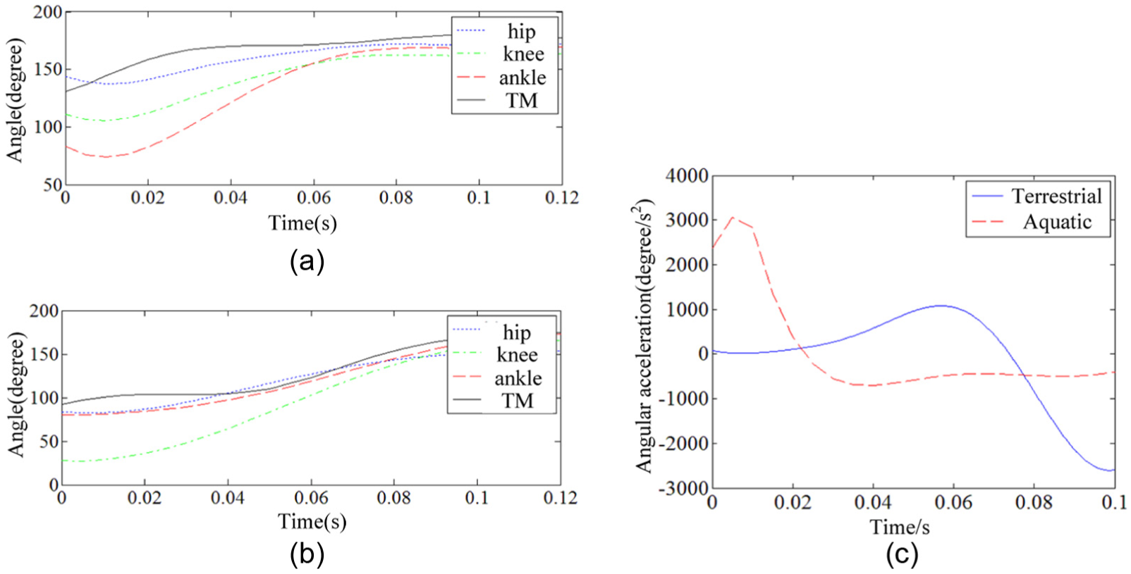
Joint trajectories of the frogs: (a) aquatic frog, (b) terrestrial frog, and (c) palm angular acceleration.
To explain the relationship between hydrodynamic forces and swimming patterns, the hydrodynamic force on the palm can be divided into drag component (force opposing to velocity) and lift component (force perpendicular to velocity) according to equation (1)

where Fdrag is the drag force on the palm, Flift is the lift force,
Given the complex palm motion, force, and velocity distributions are nonuniform, the acting points of palm velocity and hydrodynamic force were centralized at a selected point p (xp, yp) on the palm, which was 11 mm away from TM joint. This point was near the largest spanwise length to evaluate resultant force and velocity, which is denoted as equation (2)

where (xp, yp) is the position of the point p, θ4 denotes the angle of TM joint, and rp is the distance from TM joint to point p. The unit vectors regarding calculating velocity could be obtained as equation (3)

Results
Hydrodynamic propulsion from CFD
Both frogs’ palm thrusts (hydrodynamic forces in negative x axis) and body resistant forces solved from CFD simulations are shown in Figure 3. Xenopus laevis’ maximum thrust was 0.044 N and the resistant force was 0.007 N, while for Rana nigromaculata were 0.022 and 0.004 N, respectively. That illustrated quite an unsteady process of the frog swimming. Palm propulsive force became the decisive factor for swimming performance. The propulsive force was large before 0.03 s for Xenopus laevis. While for Rana nigromaculata, the propulsive force increased slowly and reached the peak in the late of propulsion phase. Then, propulsion dropped and kept a relative low propulsive force. From the motion pattern displayed in Figure 2, the joints rotated fast before 0.04 s, especially for the palm rotation in the aquatic frog, and the terrestrial frog joints intensely rotated after 0.04 s. Therefore, the peak of the motion is consistent with that of the thrust force, which caused the different thrust in the frogs. The extremely high thrust at the start point of propulsion was considered from the CFD method, which is sensitive to initial condition.

Force results from CFD calculation.
Lift and drag components in the thrust
To illustrate the propulsion generation mechanism, palm results were integrated in Figure 4. The bold green segments represent the palms sliding on the end tracks of hind legs. The representative results of hydrodynamic forces were extracted from the CFD results, and the velocity vectors were calculated by equation (2) in MATLAB. The angles between hydrodynamic force and velocity (force–velocity angle) were different from aquatic and terrestrial frogs. The force was almost opposite to the palm velocity in Rana nigromaculata, while in Xenopus laevis, the minimum force–velocity angle was about 118° during the second part of propulsive phase, which represented the lift component in propulsion. Furthermore, hydrodynamic forces were decomposed into drag and lift to analyze the hydrodynamic variations from aquatic mode to terrestrial one.
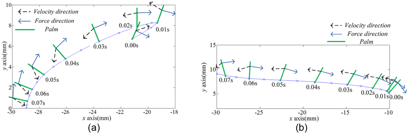
Palm motion and hydrodynamic force vectors: (a) results of the aquatic frog and (b) results of the terrestrial frog.
Figure 5 shows the hydrodynamic forces on the palm, and the lift and drag components were solved according to equation (1) in MATLAB. The results showed both drag and lift components in Xenopus laevis (Figure 5(a)). Drag force had a high magnitude and was the major propulsion during the first half in Xenopus laevis. However, drag component became negative after 0.044 s. This means that the palm movement directed opposite to swimming axis no longer provided effective thrust. Lift component became the major propulsion during the second half. The propulsive phase was divided into drag stage and lift stage by the time 0.036 s when the lift component began to exceed the drag. Therefore, for the selected swimming trial of Xenopus laevis, the propulsion generation mechanism was based on both drag and lift. While, in Rana nigromaculata, Figure 5(b) clearly shows that lift force barely contributed to propulsion. Therefore, its propulsion mechanism was drag-based.

Propulsive components on the palm: (a) results of the aquatic frog and (b) results of the terrestrial frog.
Flow field results
Flow field analysis could assist to understand how kinematic difference caused drag and lift propulsive forces. The CFD method could obtain not only the results of forces exerted on frog but also results of flow field data. Figure 6 shows the vortices distributions of the two swimming trials in coronal plane.
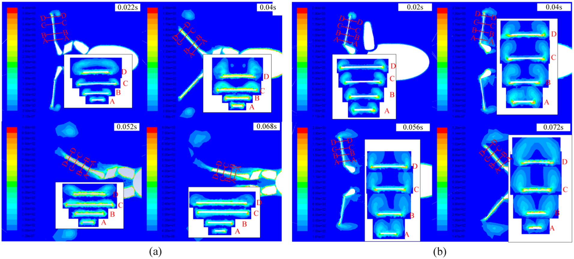
The shedding process of the vortex ring around the palm: (a) Xenopus laevis and (b) Rana nigromaculata.
The inserted figures show distributions in transverse plane in the cross sections A to D on the frog palm. Leading edge vortex could be observed in section D and the coronal plane, while side edge vortex could be observed along sections A to C. Both kinds of frogs produced apparently different flow structures. In Rana nigromaculata’s swimming trial, no significant lift effect was found. The frog palm showed a large initial angle of attack at the beginning of propulsive phase with little rotation, causing the pressure to be distributed uniformly on the suction face. The edge vortices were initially formed by the palm acceleration. Forming and shedding of edge vortices on leading (the distal edge) and side edges were almost synchronous, as shown in Figure 6. The vortex loop was about parallel to the palm and oriented in swimming axis. That indicated a thrust in swimming direction just as the denoted force in Figure 4(b). Therefore, the flow field results were in accord with the calculated hydrodynamic forces. From those results, it concludes that the swimming process of Rana nigromaculata in this article utilized drag-based propulsion, which was consistent with Johansson and Lauder’s 15 results.
For Xenopus laevis, it intensely accelerated translationally and rotationally at the beginning of swimming, and the edge vortices were generated and attached around the edges. In the early stage, the attack angle of palm maintained about 90°, and velocity in x direction was dominant (0–0.022 s, as shown in Figure 4). In this period, edge vortices were fully developed and bounded around palm edges. With palm rotation, velocity distribution was linear along the palm length (the distal got fast), this velocity variation caused pressure gradient, and thus leads to edge vortex shedding asynchronously. The leading edge vortex developed and shed faster than the proximal side. Therefore, the side edge vortices shed gradually from the distal to the proximal following the leading edge vortex shedding. The shedding vortices formed a loop from the middle side edges, which is a U-shaped vortex loop, moving slowly toward downstream (Figure 6(b)) as described in the diving bird. 16
Discussion
Palm thrusts from BEA and CFD results
To analyze the aquatic frog thrust, we conducted the BEA according to Richards 10 and obtained BEA thrust results as shown in Figure 7. BEA computes the thrust by dividing it into added mass force, which is the function of acceleration, and quasi-steady force, which is the function of velocity. The added mass force is palm’s reactive inertia force from the added fluid mass which is accelerated by palm movement. The palm in a steady flow will be acted with the resistant force from the flow, and the quasi-steady force can denote that force neglecting the dynamic effect of the flow. In the terrestrial frog swimming, the large thrust was generated in the late of propulsion by the palm rotation. However, the large thrust was generated in the early of Xenopus laevis’ propulsion by the accelerating motion, and it was reflected with the results from BEA. Then, the BEA results showed significant drop from CFD results when the thrust was generated from the fully developed flow field and were barely influenced by the initial condition interferences. The quasi-steady force was calculated with the largest coefficient extracted from plate experiments, and it matched but still had a little drop with the CFD results in the period of 0.025–0.065 s. Along with the added mass component, the resultant hydrodynamic force showed a big gap. Therefore, the added mass force may not be formed as much resistant force as in the period of 0.025–0.065 s.
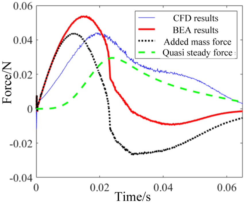
Results from CFD and BEA calculations for Xenopus laevis.
In the terrestrial swimming trial, the palms in water experienced similar hydrodynamic loads as the plate in water facing a certain inflow that means little relative rotation for the plate. Therefore, the BEA method based on the coefficients from plate experiments could achieve reasonable results in drag-based mechanism as in Rana nigromaculata’s swimming trial. As to the aquatic swimming process which contains remarkable palm rotation, thrust results from BEA were computed as shown in Figure 7. The palm acceleration was in the early period (0–0.02 s), and the thrust in that period was dominated by the acceleration reacting force. The thrust generated by palm motion in the following period was insufficient compared with the results from CFD.
Based on the components of BEA results, it is reasonable to consider the reason for the propulsion lack as two reasons. First, the negative added mass force was supposed to be overestimated, because the added mass is hypothetical such that the added mass will not as fixed as the solid mass and may not drag the palm during decelerating backward motion. Second, lift mechanism may generate higher force than expected from BEA calculation where the coefficient was set as the largest value 2. Even the quasi-steady thrust (the possible max thrust when ignoring the negative added mass force) was still lower than CFD thrust, the coefficient used in BEA, which was extracted from plate experiments as previously described, may be improper to describe the hydrodynamic situation.
Palm kinematics and the propulsion generation mechanism
Drag thrust is generated by the palm vertically moving backward in the swimming axis, but with the swimming velocity increase, the palm backward velocity will finally come to zero when the drag force no longer generated. However, the lift thrust is still generated by the palm rotation, though the palm moves forward. Therefore, the angle of attack, palm rotation and translational trajectory are decisive for thrust generation. The curved palm trajectory contributes more to the palm rotation than the straight trajectory in terrestrial frog. The palm rotation is consistent with the thrust as previously described. From Figure 4, the palm of the terrestrial frog maintained a large angle of attack during the whole propulsion, and the similar angle of attack was detected in the early phase of the aquatic swimming when the drag thrust was dominating. However, during the lift-dominant phase, the aquatic frog showed a small angle of attack. Therefore, the various motions determine the thrust generation mechanism.
The lift propulsion mechanism complicated the thrust calculation, especially the method based on the regular drag flow field, but the lift thrust could benefit frog swimming. The results described in section “Flow field results” explained the lift mechanism in terms of the flow structure around the palm. Those results imply that rotation is a key factor for generating the low-pressure centers with the symbol of the U-shaped vortex ring. Johansson and Norberg also studied frog propulsion mechanism by DPIV method14,15 which can provide the flow structure results, but the study object was the terrestrial frog, Rana pipiens, whose motion mode was similar to Rana nigromaculata in this article. Johansson analyzed the flow field and found that the orientation of the vortex rings generated by the frog feet was almost perpendicular to the swimming direction and there was only a slight asynchrony of the shedding of the distal and proximal vortex rings, which was different from the lift-dominant mechanism. Those results were consistent with the CFD results in our article in Rana nigromaculata (Figure 6(b)). However, the lift mechanism was detected in the aquatic swimming trial, so, it can be concluded that the lift thrust can be involved with different palm kinematics, and therefore, correction on the propulsive force calculation should be considered.
Thrust in the late propulsive period
From the hydrodynamic force analysis and flow field results, lift mechanism was detected in Xenopus laevis in the lift stage of propulsive phase, which was distinctly different from Rana nigromaculata. In some other researches, the calculated thrusts were always smaller than the expected propulsion in the late of propulsive phase. Gal and Blake7,8 calculated frog propulsion via BEA, and propulsion lack problem showed up in the late of propulsive phase. They used the kinematic data from an aquatic frog, Hymenochirus. Our results in drag stage of propulsive phase have a similar trend toward their propulsion results. As to the propulsion lack in the late of propulsive phase (corresponding to the lift stage in our results), Gal and Blake proposed the hypothesis of jet effect from interaction of the concentrating palms, while we think that the lift mechanism may work in this stage as was in Xenopus laevis’ swimming trial in this article. From the results of the flow field in Figure 6(a), the vortices forming, developing and shedding were bound on the back face of the palms. The vortex rings shed in the downstream were also moving backward and outward, so no sign showed the interaction of the concentrating palms.
Although the propulsive phases of the two swimming trials were analyzed, CFD method consumes a large amount of calculation such that simulations were conducted with a very short period. Therefore, more simulations should be calculated to provide diverse results for thrust analyses.
Conclusion
This article calculated the thrusts from an aquatic frog and a terrestrial frog by CFD method, and the thrust was divided in terms of palm movement to research the thrust generation mechanisms for both frogs. The distinct movement patterns caused different hydrodynamic results that the early part of the aquatic frog’s swimming is similar to the whole swimming phase in terrestrial frog when the drag component contributed the majority of the thrust, while lift component contributed to propulsion in the late of propulsive phase in the aquatic swimming trial. In the aquatic frog, the vortex ring shed gradually from the distal to proximal palm during the palm rotation, formed a U-shaped vortex ring which refers to a lift involve mechanism. However, in the terrestrial frog, the vortex ring shed almost synchronically, and drag component makes the majority of the thrust. CFD method could extend the way to analyze thrust in frog swimming and further reveal the relation between palm kinematics and propulsion mechanisms.
Footnotes
Academic Editor: Chuanzeng Zhang
Declaration of conflicting interests
The author(s) declared no potential conflicts of interest with respect to the research, authorship, and/or publication of this article.
Funding
The author(s) disclosed receipt of the following financial support for the research, authorship, and/or publication of this article: This work was supported by the National Natural Science Foundation of China (51675124).