
Abstract
Wind energy plays a significant role in the energy consumption reduction of the sail-assisted vessels. During the navigation process, how to select the ideal airfoil sails is crucial for the vessel safety and wind energy conversion efficiency. We resolve the airfoil sails selection problem by utilizing computational fluid dynamics simulation. Within the computational fluid dynamics simulation approach, with shear-stress transport k–ω turbulence model, we analyze the performance of the three typical airfoil sails including NACA23012, NACA0012, and NACA0018 in the wind field from the perspective of force condition, lift and drag coefficients, and lift–drag ratio under generous wind speeds and angles of attack. And we investigate the pressure contours of the airfoil sails. Then, we can determine the aerodynamic performance of the airfoil sails promptly and identify suitable sails for the sail-assisted vessels under the given wind field.
Introduction
With the globalization of the world economy, the seaborne trade grows steadily and accounts for
The sail has been employed in aid of the vessel navigation for quite a long history. 9 There are more than 10 kinds of mainstream sails with different shapes, operating principles, and aerodynamic characteristics. 10 Generous sails including flying jib, 11 square sails, Princeton sails, 12 Magnus roll sails 13 and wing sails have been adopted for sail-assist propulsion of vessels. 14 Flying jib is often used in sailboats for recreation and competition.11,15 Mainly relying on drag force, 16 wind energy utilization efficiency of square sails is low. Because the canvas is around the mast, the maintenance costs of Princeton sails are quite high. 14 Within the principle of Magnus sail, its cylinder rotates vertically around the rotary axis on deck, and the workload can be regulated by varying drum speeds. The reliability of Magnus sail is relatively high, while it consumes additional energy. 17
The ideal sails for sail-assisted vessel are characterized by excellent aerodynamic performance and economical maintenance cost. Structure of wing sail is similar to an airplane wing with airfoil cross-section. 18 Featured by much better lift-to-drag ratio than conventional sails, wing sails have been extensively adopted in contemporary sail-assisted vessels.3,8,16,18 The most representative wing sail can be the series of the NACA airfoil developed by the National Advisory Committee for Aeronautics (NACA). 19 NACA has constructed a considerable database for airfoils. Referring to NACA airfoil, its aerodynamic performance precedes other sails and it has been employed in aviation and navigation for many years. In the field of sail-assisted vessel navigation, the airfoils amounted on the vessel can be treated as the wings of an airplane. Consequently, we select three classical airfoils named NACA23012, NACA0012, and NACA0018 from NACA database and present the way to compare and select the feasible airfoils for vessel under certain navigation environment from the perspective of aerodynamic performance.
Generally, the wind tunnel test is often employed to identify the airfoil performance.3,16 Li et al. 3 tested the performance of cascade hard sails under the scale wind tunnel environment and found that the performance of the cascade sails closely linked to the distance between sails. He et al. 16 was primarily concerned with the aerodynamic performance of a sail by employing the wind tunnel test, and the stability of sail-assisted vessels from the perspective of stability criteria calculation. However, confined to the expensive experiment expenditure and unstable results, the wind tunnel test is generally replaced by computational fluid dynamics (CFD) simulation20–23 when selecting hard airfoil sails. Consequently, we tend to conduct fluid simulation modeling of the airfoil hard sail for the sail-assisted vessel by adopting CFD.
Some highlights of our paper are as follows: (1) CFD is applied for fluid simulation modeling of the airfoils mounted on the sail-assisted vessels; (2) and performance of the NACA airfoil sails are analyzed in detail including lift and drag coefficients under generous angles of attack and wind conditions, the pressure contours are analyzed in detail. Finally, new sights into the airfoil hard sail selection for the sail-assisted vessel are presented using our developed approach.
Airfoil hard sail modeling and force analysis
Airfoil hard sail modeling in the wind field
Figure 1 shows the two-dimensional diagram of three NACA sails, NACA0012, NACA0018 and NACA23012. It can be found that the structure of the first two sails is symmetrical, and that of the third sail is asymmetrical. The corresponding part drawings of the airfoil hard sails are presented in Figure 2.

Two-dimensional diagram of three NACA sails: (a) NACA0012, (b) NACA0018, and (c) NACA23012.

Part drawing of the airfoil hard sails (a) NACA0012, (b) NACA0018, and (c) NACA230012 with CATIA.
The airfoil hard sail modeling in airfoil field is illustrated below. First, export the data from the airfoil hard sail database in the form of a txt file and set the value of the Z-axis to 0 mm. Then, import the txt file into the software SolidWorks and transform the airfoil data into an entity reference. And connect the tail of the airfoil as shown in Figure 3.

Tail connection.
Following that, after connecting the fore and aft of the airfoil using a straight line, the reached line can be treated as the airfoil center line. The determined center line is presented in Figure 4.

Center line determination.
Third, stretch the two-dimensional (2D) airfoil and convert it into a three-dimensional (3D) model and then save the 3D model as the part drawing of the airfoil hard sails. Figure 5 shows the 3D model of the airfoil hard sail.

Three-dimensional model of airfoil hard sail.
By modifying the shape of the airfoil hard sail in the air flow field and rotating the airfoil model as shown in Figure 6, we can adjust the angle of attack of sails correspondingly.

Rotation of airfoil model.
Finally, suppose the airfoil material is smooth, and check the closure of the airfoil. Based on the airfoil hard sail modeling process, we can develop the airfoil model for numerical simulation accordingly.
Force analysis of airfoil hard sail
Figure 7 demonstrates the force analysis of the airfoil hard sails that mounted on the sail-assisted vessel. Within the
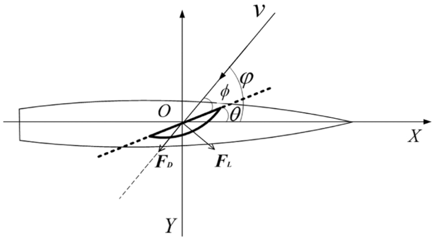
Force analysis of the airfoil hard sail.
The force of the airfoil hard sail can be divided into the drag force


The thrust


Suppose


Numerical simulation approach
Governing equations Shear-stress transport k–ω model
Referring to the shear-stress transport (SST)

And momentum equation is

Details of the model can be referred to Menter, 24 Mao et al., 25 and Wilcox. 26
Simulation flow for airfoil hard sail
By employing our constructed airfoil sail model, with the aid of the software SolidWorks, we can calculate the lift and drag coefficients
Import the sail model into flow simulation of SolidWorks, and suppose the flow field is the external flow field of the airfoil hard sails.
Referring to the selection of flow medium, we choose air as the external flow field of the airfoil hard sails.
Set the velocity and the turbulence intensity of the air flow field.
Select the 2D computational domain for airfoil hard sails, and the domain should be large enough to contain the airfoils.
Present the global variables, and set the variables, including
Start the calculation with the solver embedded in the software and obtain the results.
Simulation results and discussions
To probe into the insights of the airfoil hard sails that adopted for sail-assisted vessel, we carry out several numerical simulations under generous scenarios. Suppose the relative wind speed
Results of
and
Tables 1, 3 and 5 show the drag force coefficient
Drag force coefficient

Lift force coefficient

Figures 8–10 demonstrate the drag force coefficient

(a)

(a)

(a)
In Table 1, the minimum
In Table 3, the minimum
Drag force coefficient

Lift force coefficient

In Table 5, the minimum
Drag force coefficient

Lift force coefficient

Results of contours of statistic pressure
Figures 11–13 plot the pressure contours of NACA23012, NACA0012, and NACA0018 under varied angles of attack
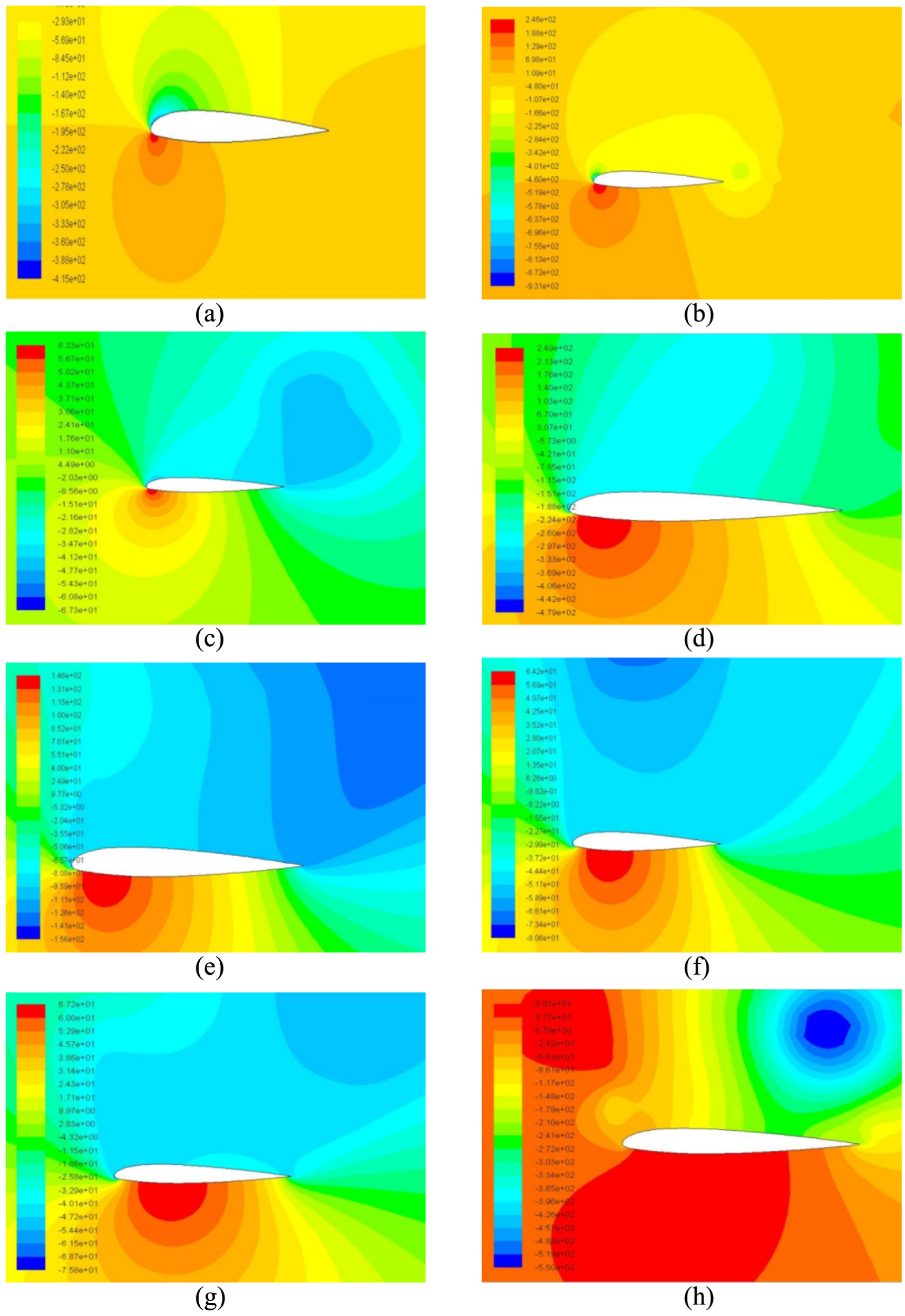
Pressure contours of the airfoil hard sail NACA23012 under varied angles of attack

Pressure contours of the airfoil hard sail NACA0012 under varied angles of attack

Pressure contours of the airfoil hard sail NACA0018 under varied angles of attack
The vertical bar scale with different colors on the left part in Figures 11–13 indicates the pressure value. Red color of the bar means the pressure of this part is markedly higher than standard atmospheric pressure, and the airfoil hard sail would encounter a large wind pressure under which condition the sail is prone to damage. The blue part signifies that its pressure is navigate and significantly lower than standard atmospheric pressure, and stall phenomenon would be generated when sail located in this region. Green color implies that the pressure of this part is close to standard atmospheric pressure, and the sail would experience a relative small force in the wind field corresponding to the green color.
New insights into airfoil hard sail selection for sail-assisted vessel
Generally, referring to
When the relative wind speed
Referring to
Consequently, when we probe into the phenomenon in Figures 8–10, new insights can be achieved as follows: (1)
From the perspective of the pressure contours of the airfoil hard sails, we find the following new insights from in Figures 11–13. (1) For one certain airfoil hard sail operating at the given relative wind velocity
Since the pressure value in the deep blue region is below 0, the energy saving efficiency by employing the airfoil hard sails is low. Therefore, it is all utterly senseless and pointless using the sails for sail-assisted vessel under those similar situations. Correspondingly, to ensure the performance of the airfoil hard sails in the wind field, it is necessary to enhance the structural strength of the sails especially on the part of its leading edge. Furthermore, to fulfill the ideal energy saving efficiency for the sail-assisted vessel, it is significant to equip with flexible gears on the vessel in order to drive the sails to the reasonable angle of attack
Conclusion
By employing the CFD simulation approach, several new insights have been found referring to the ideal airfoil hard sail selection for the sail-assisted vessel. Within our proposed approach, the critical factors including lift and drag coefficients, lift–drag ratio, and pressure contour of the candidate sails are investigated thoroughly. The performance of the airfoil hard sails has been demonstrated in detail. Numerical simulations under multiple scenarios have been developed. Accordingly, we present the deep new insights, including ways to select the ideal sails for the sail-assisted vessel, the appropriate time to use the sails, and the damage-avoidance instructions during sail operation. In the near future, with the aid of techniques including energy big data and path planning,27–29 we would develop the operational intelligent sail selection system for the shipping industry application.
Footnotes
Handling editor: Zhixiong Li
Declaration of conflicting interests
The author(s) declared no potential conflicts of interest with respect to the research, authorship, and/or publication of this article.
Funding
The author(s) disclosed receipt of the following financial support for the research, authorship, and/or publication of this article: The authors are partially supported by the National Science Foundation of China (51579202, 51309186, 61673223, 71501151, 61773401) and China Postdoctoral Science Foundation Funded Project (2015T80848 and 2014M560633).