
Abstract
High-speed switching valves have been widely studied as pilot valves because of their advantages on easy digital control, low power loss, and non-sensitive to oil pollution. However, there are still lots of difficulties and problems between discrete flow and response time. In this article, two high-speed switching valves are used to pilot a three-way main stage valve. By adjusting the duty ratio of pulse width modulation control signals, the main stage can output continuous flow and pressure. The control performances of two pilot stage methods, which are high-speed switching valve and proportional valve, are compared through the theoretical analysis and the dynamic simulation. It is found that three factors directly affect the response time of the main stage, which are the control signal, the operating frequency of high-speed switching valve, and the pressure of the control chamber. The main valve can achieve better performance if optimized parameters are applied.
Introduction
The high-speed switching valve has been under active research for decades. The idea to replace continuously adjustable proportional valves by a certain number of simple on/off valves is known as digital hydraulics. 1 For conventional hydraulic valves, the volume flow is controlled by opening or closing an orifice by means of a spool. For digital valves, the volume flow is controlled by on/off fluid. 2 Compared with servo or proportional valves, high-speed valves have benefits of easy digital control, low power loss, and non-sensitive to oil pollutions. Recently, the research on high-speed valves focuses on improving the dynamic performance of high-speed electrical–mechanical actuator, flow force compensation, digital signal for rapid switching, and control performance.
T Lantela et al. 3 studied the performance of a solenoid actuator with five kinds of soft magnetic material as well as the number of coil turns, the size of coil on the response time, and the energy consumption of the actuator. Xiaowu Kong and Shizhen Li investigated a new scheme of parallel coils to increase the magnetic force of armature and the slew rate of coil current. Both the delay time and the switching time of solenoid valves can be decreased greatly by adopting the parallel coil scheme. 4 M Linjama et al. 5 used a certain number of high-speed switching valves to implement parallel connected digital hydraulic system called digital hydraulic valve system (DVS), in which the control method, the reduction of pressure peaks, fault detection and compensation were considered. Feng Wang studied a hydraulic pressure converter utilizing high-speed switching valves to output continuous pressure by changing the duty ratio of the pulse width modulation (PWM) signal. The results also showed that the output pressure fluctuation is greatly influenced by the PWM signal frequency. 6
Besides, some types of high-speed switching valves have already been manufactured for industrial use. Linz center of mechatronics developed a kind of digital valve called fast switching valve with integrated electronics (FSVi). It can control the solenoid current instead of voltage and protect the electronic device with the help of a microcontroller and an integrated controller area network (CAN) interface. The FSVi had a nominal flow rate of 10 L/min at a pressure drop of 5 bar with maximum frequency up to 100 Hz. 7 The NACHI in Japan designed a two-way high-speed valve with poppet valve structure. The rated frequency can reach 50 Hz, with pressure at 7 MPa and flow at 8 L/min. 8 The high-speed switching valves were widely used in antilock brake system (ABS) and fuel injection of vehicles. 9 The Kelsey-Hayes developed a special step-shape armature valve applied in ABS. The advantages were fast respond time (<3 ms) and high pressure (<21 MPa). 10 Caterpillar Inc. invested a new diesel engine fuel system using high-speed switching valve. The high-speed switching valve was driven by 110 v and can acquire an extremely opening time about 1 ms. However, the difficulty of component processing limited its applications. 11
Most of the researches concentrated on direct-driven high-speed switching valves. Due to the limitations of the valve stroke and magnetic force, it is hard to achieve high pressure and large flow simultaneously. Therefore, high-speed switching valves are used as pilot valves, which is an important way to realize wider applications. Based on this, Sauer-Danfoss Inc. developed an electrical actuation unit for hydraulic proportional valves. It contained four high-speed switching valves used as pilot. The control pressure was 1.35 MPa with max 5 L/min. 12 Parker Inc. also launched a kind of multi-directional valve with two high-speed switching pilot valves. The PWM signal was used as pilot control signal whose frequency is 33 Hz. 13 In C Wen et al., 14 the mathematical model was established on the basis of cartridge valves controlled by high-speed on/off valves. The spool displacement of cartridge valve and outlet flow were analyzed. Jinyuan Qian analyzed the pressure difference of pilot valve under different static pressures, inlet velocities, and different orifice diameters. The opening and closing characteristics of main valve were studied. 15 B Xu et al. 16 built a detailed dead-band model describing the relationship between pilot valve spool and the flow rate. A simple and effective method was proposed to detect the varying dead-band values in the pilot stage. It can be used for online detection without affecting the hydraulic system where the two-stage valve was involved.
This article focuses on high-speed switching valves used as pilot valves. Multiple parameters of pilot high-speed switching valve system are considered in experiments, including frequency of pilot valves, control pressure of main stage chambers, pilot flow capacity, and control signals. The basic idea is that a three-way main stage valve is controlled by two high-speed switching valves in each chamber, as shown in Figure 1. By adjusting the duty ratio of PWM control signal, the main stage can output continuous flow and pressure. The key difficulty is using discrete flow to equalize the effect of continuous control performance. Both theoretical analysis and the dynamic simulation have shown the control performance of high-speed switching pilot valves and proportional pilot valves. The results confirm that high-speed switching valves are a good solution as pilot valves if with optimized parameters.

Diagram of pilot high-speed switching valve system.
Working principle
The pilot high-speed switching valve system is shown in Figure 1. The system consists of four parts: PWM signal and high-speed solenoid, pilot high-speed switching valves, control chamber, and main stage valve.
The electrical part contains a control system (controller, data acquisition card, PWM signal generator, and CAN bus interface) and electrical–mechanical actuators. The controller gives the duty ratio according to the feedback of pressure sensor at the outlet of the main stage valve as well as the feedback of displacement sensor which measures the main stage spool. High-speed solenoids receive PWM signals and export corresponding forces. The pilot high-speed switching valves flow capacities are set on the basis of binary PWM sequences. There are two control chambers at each side of the spool. Since the delay of response time and the effect of the chamber volume, the main stage spool will get a constant force. Consequently, the main stage can output continuous flow depending on the control signal and provide the displacement of the spool feedback.
PWM signal and high-speed solenoid
The controller generates PWM signals. By adjusting the duty ratio, the high-speed solenoid gets different on/off time, bringing corresponding flow. Since the switching time is fast enough and the flow is not a transient value, the high-speed switching valve will output a delay flow. Figure 2 demonstrates the PWM signal, the current in high-speed solenoid, and the action of the high-speed switching valve in a same timeline.
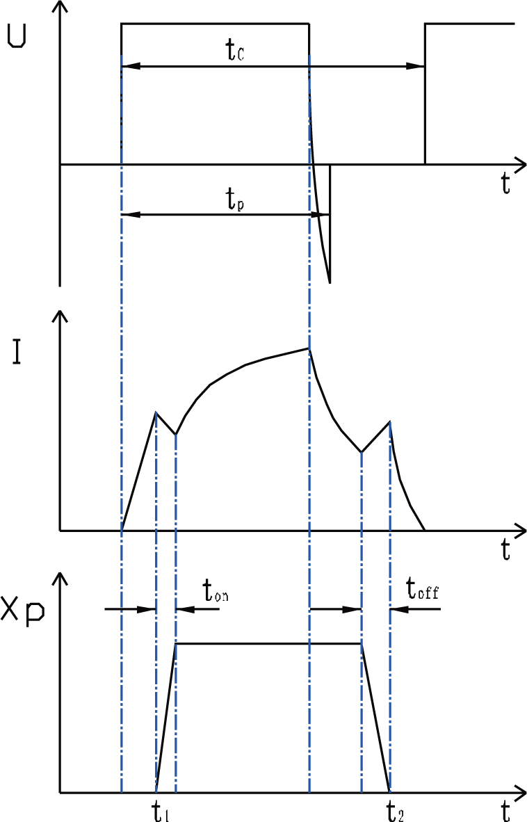
The PWM signal and action of the high-speed switching valve.
When the high-speed switching valve is fully open, the current in solenoid will keep on rising due to the high level voltage. This leads to longer closing time than opening time. In this article, a transient reverse voltage at the start of the closing time is given in order to have a preferable closing time.
In the PWM control mode, the periodic carrier wave
The dynamic of the high-speed solenoid can be written as

where U is the driving voltage, R is the equivalent resistance, I is the current of coil, and L is the equivalent inductance.
Based on electromagnetic theory, the force given by high-speed solenoid can be written as 17
where

For a whole cycle, the output force of the electromagnetic is the average value.
Pilot high-speed switching valve
The pilot high-speed switching valve is the key component of this system. A fast-response three-way valve with two-position is designed. The three ports of the high-speed on/off valve are the high-pressure flow port P, the control pressure flow port A, and the return flow port T, as shown in Figure 3.

Structure of the high-speed switching valve.
In general, there are three types of high-speed switching valves: ball valves, slide valves, and poppet valves. Slide valves have advantages such as easy pressure balance implementation and friendly to processing, but large flow leakage in pilot valve is intolerable. Poppet valves are well sealed, whereas it is hard to ensure concentricity. Besides, when it is used in high-speed on–off situation, abrasion is unbearable. For ball valves, they are approved comprehensively for less mass with lower leakage.
The rated pressure and rated flow of the pilot valve are 2 MPa and 2 L/min, respectively. The parameters of the pilot high-speed switching valve are shown in Table 1.
Parameters of pilot high-speed switching valve.

The spool dynamics of the pilot high-speed valve can be obtained

where
As the flow area of ball valve can be expressed as

The flow equations of pilot high-speed valve are


where
Chamber pressure dynamics
The chamber pressure dynamics is determined by the compressibility of the fluid between the pilot stage and the main stage in the chambers. 18 The basic formulas used in terms of the flow rate and volume are as follows

where
Main stage valve
The main stage valve is a traditional proportional valve with overlap for reducing leakage. A linear variable differential transformer (LVDT) displacement sensor attaches to the spool which gets feedback from spool displacement to data acquisition and control system. If the transient flow forces can be neglected, the spool dynamics is expressed as follows
where

For a particular valve,
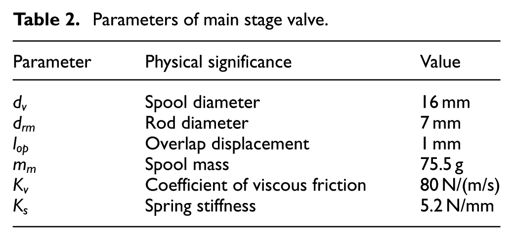
Parameters of main stage valve.
When the load force

where
Effect of pilot high-speed switching valve system
The pilot high-speed switching valve system is manufactured. It contains two high-speed switching valves, pilot valve block, main stage block, main spool, LVDT displacement sensor, and two pressure sensors, as shown in Figure 4.

The pilot high-speed switching valve system.
The performance of high-speed switching valve system is studied by experiments. The opening time and the closing time are important indexes.
Figure 5 demonstrates the opening time and the closing time of the pilot high-speed switching valve. The red line is the ordinary PWM signal with duty ratio of 0.5 and frequency of 100 Hz. It could be seen that the delay time is 1.65 ms at valve open and 2.8 ms at valve closed. The time of valve closing is much longer than that of valve open.
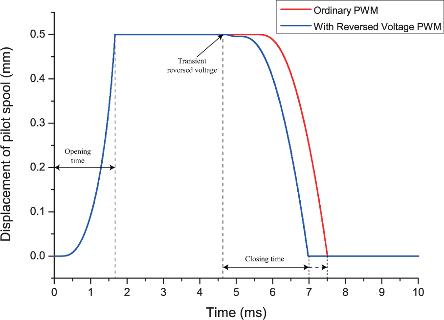
Opening time and closing time of pilot high-speed switching valve.
As described in Figure 2, a transient reverse voltage at the start of the closing time is adopted. The transient reverse voltage is inflicted at 4.6 ms, so that the current in coil of pilot high-speed switching valve descends immediately. Thus, the ball valve closes more quickly by the hydraulic force. The closing time can decrease by 0.5 ms. The blue line is the result after the method is used. The performance of pilot valve with different frequencies is studied, as shown in Figure 6.

Main stage valve flow at different frequencies.
From Figure 6, it is obvious that the flow rate of main stage is more stable as the frequency of the pilot high-speed switching valve increases. When using 10 Hz, the main stage valve cannot output continuous flow. The high frequency also reduces the overshoot of valve flow. That is because the higher the frequency of the high-speed switching valve, the faster the frequency of control adjustment. Through the displacement feedback signal of main stage valve, it can also be confirmed, as illustrated in Figure 7.

Main stage spool displacement at different frequencies.
From the pilot high-speed switching valve to the main stage valve, there are two control chambers at each side of spool. The pressure in chamber, which is also called the pilot pressure, directly influences the main stage performance. Figure 8 shows the main stage spool opening time with pilot pressure at 0.5, 1, and 2 MPa.

Influence of control pressure.
The results show that with the pilot pressure increasing, the main stage valve spool can have a faster dynamic performance. Nonetheless, the control pressure should be balanced with the high-speed solenoid force
Comparison of the switching valve and the proportional valve
In order to assess the quality of the pilot high-speed switching system, the simulation which is based on the theory and equations above for tracking main stage valve spool displacement of sine function is carried out. The high-speed switching pilot valve and the proportional pilot valve are compared. The simulation models are built with the parameters in Table 3.
Parameters of simulation.

The displacement of main stage valve spool is ±4 mm. The setting sine wave has the amplitude of 4 mm with the frequency of 1 Hz. Figure 9 shows the comparison between the proportional pilot valve (left) and the high-speed pilot valve (right).

Displacement of main spool using proportional pilot valve (left) and high-speed valve (right).
From the result, it can be seen that the displacement of main stage valve can also track the sine signal but with vibration using pilot high-speed switching valve. The reason is that the pilot high-speed switching valve is always in the state of on/off during working.
For the sake of comparing the control performance between pilot high-speed switching valve and pilot proportional valve, two methods are used to control the displacement of a hydraulic cylinder, as shown in Figure 10. It is affirmed that two methods for pilot valve can have nearly the same performance. The displacement error is not more than ±0.15 mm.

Comparison of hydraulic cylinder’s displacement between high-speed switching pilot valve and proportional pilot valve.
Conclusion
In this article, the idea of using high-speed switching valves as pilot valves is discussed. A three-way main stage valve is controlled by two high-speed switching valves in each control chamber. The model includes four parts: PWM signal and high-speed solenoid, pilot high-speed switching valves, control chamber, and main stage valve. The main stage can output continuous flow and pressure by adjusting the duty ratio of PWM control signals. Theoretical analysis of pilot helps to acquire dynamics, pressure and flow regulation, so that an experiment and a simulation are designed.
The key parameters which greatly influence the performance of pilot high-speed switching valve system are studied. There are three factors directly affect the response time of the main stage: the PWM control signal, the frequency of pilot high-speed switching valves, and the pressure of the control chamber. For a better PWM control, a transient reverse voltage at the start of the closing time is adopted; thus, the response of high-speed switching valve can be improved. The frequency of high-speed switching valve shows the faster the pilot valve moves, the more excellent flow rate characteristic is. As to main stage, it is shown that if the control pressure in chamber is properly improved, the displacement of main stage spool would get a balance position faster.
The differences of control performance between high-speed switching valve and proportional valve used as pilot valve are compared in this article. Simulation models of two systems valve are established. With the same external parameters, the results show that the main stage can work well if the continuous pilot components are replaced by high-speed switching valves. Although the displacement of main stage with high-speed switching valve has vibration, the displacement tracking simulation of hydraulic cylinder has only largest error in ±0.15 mm. Therefore, with the advantages of high performance, good control properties, and low power cost, the pilot high-speed switching valves are very promising for two-stage valves system.
Footnotes
Appendix 1
Academic Editor: Jianqiao Ye
Declaration of conflicting interests
The author(s) declared no potential conflicts of interest with respect to the research, authorship, and/or publication of this article.
Funding
The author(s) disclosed receipt of the following financial support for the research, authorship, and/or publication of this article: This work is funded by the “Twelfth Five-Year” National Science and Technology Support Program of China (no. 2014BAF02B00) and the Strengthening Industrial Base Project (TC150B5C0-29).