
Abstract
This paper proposes a new type of damped multi-mode switching damper based on a high-speed switching solenoid valve. The structural design of the damper is completed, and its working principle of realizing different damping modes is analyzed. A damping characteristic model of the damper is constructed, and the change rule of the damping characteristic of the multi-mode switching damper is analyzed. The seat suspension of a wheel loader is equipped with a damper that is controlled by a damping strategy. A 10-degree-of-freedom mixed-logic dynamic model of the seat suspension system is established using HYSDEL, and a multi-mode switching damper is employed. The weight coefficients are adjusted using a self-immunity control strategy, and the hybrid model predictive control method is used to complete the damping control strategy. Simulation results show that, compared with the fuzzy control strategy, the designed wheel loader seat suspension damping active disturbance rejection control (ADRC) strategy not only effectively reduces the root-mean-square (RMS) value of the driver’s vertical vibration acceleration up to more than 40% at different speeds and shock conditions, but also effectively reduces the driver’s vertical vibration acceleration. The ADRC strategy is a robust approach that achieves the desired control objective of the system.
Keywords
Introduction
As a rapidly developing integral part of construction machinery, wheel loaders not only hold a significant position in market sales but also play a crucial role in reducing work intensity, accelerating construction speed, and ensuring the quality of construction.1–3 However, during operation, wheel loaders frequently face the dual challenges of extreme vibrations and harsh operating environments, which inevitably transmit to the operator, causing physical and mental fatigue, thus affecting operational efficiency and safety.4–7
In recent years, research on the vibration control of wheel loaders has primarily focused on the design improvement of suspension seats, including passive suspension seats, semi-active suspension seats, and active suspension seats. 8 Passive suspension seats are widely used due to their simple structure and low cost. For example, Papaioannou et al. applied Pareto optimization theory to improve the structure of passive suspension seats by minimizing the resonance frequency to improve driver comfort. 9 Palomares et al. studied viscoelastic passive suspension seats and optimized their vibration isolation performance by adjusting the force characteristics of air springs and dampers. 10 However, once passive suspension seats are designed, their structure and damping values cannot be adjusted to adapt to changing road conditions and complex work environments.
In contrast, although active suspension seats provide more precise vibration isolation, their application is limited due to high cost, complex mechanical structures, and bulky actuators. For example, Sun et al. proposed a novel shock absorber that can adjust damping characteristics simply by changing the states of two solenoid valves. 11 Sinan Basaran and Basaran developed a Lyapunov-based backstepping control design for the active suspension system of tri-axial heavy vehicles to improve driving comfort. 12 Chunyu Wei et al. investigated an optimal design method for a novel output feedback H∞ controller used in active suspension seats to improve vehicle ride comfort. 13
In light of this, semi-active suspension seats are increasingly being valued for their benefits in between passive and active systems. Semi-active suspension seats maintain a simple structure and low cost, while providing a more flexible response through an adjustable damping mechanism. Recent studies have shown that the use of advanced control algorithms can significantly improve the performance of semi-active suspension systems. For example, Zhang et al. investigated a semi-active suspension seat system based on a Takagi-Sugeno fuzzy controller and demonstrated its advantages in dynamic performance. 14 Bingül and Yıldız performed multi-objective optimization on a nonlinear active suspension system for 4 × 4 wheel motor-driven electric vehicles to improve driving comfort and health standards while considering driving safety, and achieved good performance with fuzzy logic and PID controllers. 15 Qiang Chen et al. proposed a semi-active seat suspension sky-hook control method to reduce vibrations in commercial truck seats, thereby improving ride comfort. 16
Based on these studies, semi-active suspension seats utilize adjustable damping characteristics and advanced control algorithms to enhance driver comfort, but they have deficiencies in the continuity of damping adjustability. Simultaneously, semi-active suspension seat systems require measurement of seat vibration signals for control. These studies do not estimate and compensate for internal and external disturbances, and some control algorithms require precise mathematical models to achieve desired control performance. One of the primary contributions of this paper is the improvement of adjustable dampers, designing a new type of damping multi-mode adjustable damper based on high-speed switching solenoid valves, and applying it to the seat suspension of wheel loaders. Another contribution is the integration of ADRC strategies into the control and optimization algorithms of semi-active suspension seats. Initially, a 10 degrees-of-freedom hybrid logic dynamics model of the wheel loader seat suspension system is established. The ADRC control strategy is used to adaptively adjust the damping of the hybrid model, completing the design of the damping control strategy for the wheel loader seat suspension. Subsequently, the Class D of ISO road profiles is used as the excitation to verify the feasibility of the ADRC control strategy. Through random impact vibration experiments, it is demonstrated that the design has excellent robustness, can estimate and compensate for internal and external disturbances, provide a faster system response, and maximize the comfort of the semi-active suspension system of wheel loader seats.
Damping adjustable damper structure design and damping characteristic modeling
Structure and principle of the adjustable damper
Figure 1 shows the schematic structure of the adjustable damping damper designed in this paper, which is capable of switching between multiple damping modes. As can be seen from the figure, the damper is based on the conventional hydraulic damper with an external damping control device consisting of four check valves and two high-speed switching solenoid valves, and the device can change the flow path of the damping fluid in the damping control device by controlling the switching modes of the two high-speed switching solenoid valves. The device mainly controls the on/off mode of the two high-speed switching solenoid valves to change the flow path of the damper fluid in the damping control device. 17

Schematic diagram of damping adjustable damper structure.
The damping mode of the adjustable damper at different working strokes is mainly determined by the opening pressures of the four check valves, so another main feature of the damper damping adjustment device is that the opening pressures of the four check valves are different, and the specific opening pressures can be adjusted according to the requirements of the damping adjustment range. The preceding analysis has led to the identification of four damping modes that can be realized by the damper. These are presented in Table 1, which also includes the on-off state of the solenoid valve and the damping characteristics of the four modes. As the damping characteristic models and damping coefficients in different damping modes have already been studied in the literature, 18 this paper will not repeat these contents. Instead, it will focus on the establishment of the vibration model of the wheel loader cab and the design of the damping control strategy.
Switching state and high-speed solenoid condition in different damping modes.

Damping characteristics modeling of damping adjustable damper
In this paper, we take the damping mode 3 compression stroke as an example, and establish the damping characteristics of the damping adjustable damper before and after the opening of the compression valve, and the modeling process of other damping modes and different strokes is similar to this one, which is limited by the length of the paper, so it will not be repeated. 19
Before opening the compression valve
When the speed of the damper piston is low, the compression valve is not open, at this time, the damper compression damping force is mainly produced by the damping adjustment device in the check valve c, the switching valve s1, the piston assembly on the circulation valve and the bottom valve assembly on the constant through the opening, the damper oil flow model as Figure 2.

Oil flow in the damper before the compression valve opens.
In Figure 2, P1, P2 and P3 are the oil pressures in the recovery, compression and equalizing chambers respectively, and the air pressure in the air chamber is P4. According to the design principle of the cartridge damper, the total flow rate of oil from the compression chamber to the recovery chamber before the compression valve opens, Q1, can be expressed as follows:

In equation (1),

In the case of check valve c, the flow of oil

In equation (3),

In equation (4),
Since the valve plate deforms under the oil pressure to form a throttling gap, the oil flow rate through the flow valve at

In equation (5),
According to the damper oil flow shown in Figure 2, there is a relationship between the pressure difference

By combining the above equations, the specific expression for
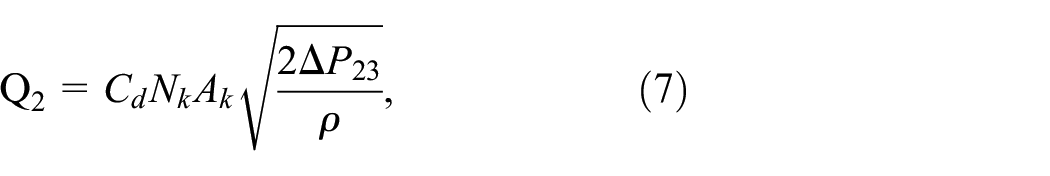
In equation (7),

In equation (8),

The force analysis of the damper piston gives an expression for the damping force

Associative equations (9) and (10), can be obtained:

When the compression valve opens
When the damper piston moves faster, the compression valve opens, and at this time, the damper compression damping force is mainly generated by the check valve c, the switching valve

Analysis of change rule of damping characteristics of damping adjustable damper
Based on the mathematical model of the damper, we can simulate and analyze the change rule of the damping characteristics of the damper with the main structural parameters of the damping adjustment device. Figures 3 and 4 show that when the other structural parameters of the damper are determined, the damping force of the damper varies with the speed of the piston under different nominal pressure losses of the check valves

Variation of damper damping force with rated pressure of check valve

Variation of damper damping force with rated pressure of check valve
From the above simulation results, it can be seen that by adjusting the nominal pressure loss of check valves a, b, c and d, the damping characteristics of the damper can be realized in different damping modes, which can effectively meet the requirements of the semi-active seat suspension of wheel loaders for a wide range of damper damping adjustment.
Dynamic modeling of loader seat suspension with mixed logic
To achieve the design of the damping control strategy for the wheel loader seat suspension with damped multi-mode switching damper, a 10 degree of freedom vibration model of the wheel loader with seat suspension is first established as shown in Figure 5. To save space, the relevant variables are briefly introduced in the figure, where the variables beginning with m all denote the relevant masses, the variables beginning with z all denote the relevant displacements, the variables beginning with k all denote the relevant stiffness coefficients, the variables beginning with c all denote the relevant damping coefficients, the variables beginning with θ and φ all denote the relevant attitude angles, and the variables beginning with l all denote the relevant distances. q is the vertical displacement input at the four wheels of the wheel loader, α and φ are the vertical displacement inputs and q is the vertical displacement input at the four wheels of the wheel loader, α and φ are the angles between the arm cylinder axis and the bucket cylinder axis and the horizontal plane, respectively.

Nonlinear wheel loader semi-active suspension seat model with human body. 24
Aiming at the vibration model of the wheel loader shown in Figure 5 and the mixed dynamic behaviors present in the seat suspension damping control process, this paper further adopts the HYSDEL compilation language for the construction of the system’s mixed-logic dynamic model, 25 and the specific modeling process is mainly composed of three parts.
System variables and parameters
Combined with the loader vibration model, the system state variables are all continuous variables, including the vertical vibration velocity and displacement of the driver, the vertical vibration velocity and displacement of the cab, and so on. The input variables include continuous variables and discrete variables, where the discrete variables are the on-off states δ1 and δ2 of the two high-speed switching solenoid valves, and the continuous variables are the inputs of the vertical displacements of the road surface at the corners of the loader. The output variables are indicators characterizing the vibration isolation performance of the loader seat suspension. The parameters of the loader seat suspension system are determined according to the relevant literature and are not given in detail here due to the large number of parameters and space limitations.
Continuous and discrete auxiliary variables
To characterize the relationship between the different damping modes of the damper and the solenoid switching states
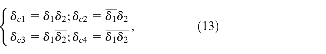
In equation (13),

In equation (14),
In order to characterize whether the damper is in compression or in recovery, the auxiliary logic variable

Equation (16) indicates that when

Update equations for the continuous mode
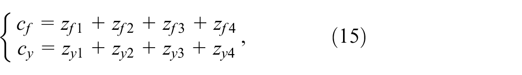
The mathematical relationships between the damping coefficients of the multi-mode switching damper and the on/off modes of the two switching magnets, as well as the dynamic travel of the seat suspension, are determined by the definitions of the continuous and discrete auxiliary variables described above. On this basis, the update equations for the continuous state variables can be obtained by combining the system vibration model. Due to space limitations, the details are not given here.
Predictive control design of a mixed damping model (MLD) for a seat suspension system
Based on the MLD model of the system, we first perform an in-depth dynamics analysis of the seat suspension system to construct a hybrid model that integrates the continuous and logic dynamics of the system. This model will include the mechanical properties of key components such as springs, dampers, seats and manikins, while incorporating logic control elements and switching control strategies. Next, we will define the objectives of the control system, which include optimizing ride comfort and ensuring system stability over a wide range of road conditions. To do this, we need to identify the control inputs, typically the damper modulation signals, and the system state variables, such as suspension travel, speed and acceleration.
Based on this, we will design a model prediction controller capable of solving an optimization problem based on the current state and model predictions to compute a set of optimal control actions during each control cycle. In this way, a predictive control strategy can be provided for the seat suspension system to adapt to the changing driving environment and road conditions.
Setting up and solving the system mixed integer quadratic programing (MIQP)
By combining the proposed system MLD model and the quadratic control objective function, defining the system optimal control input sequence, and setting t as the current moment and
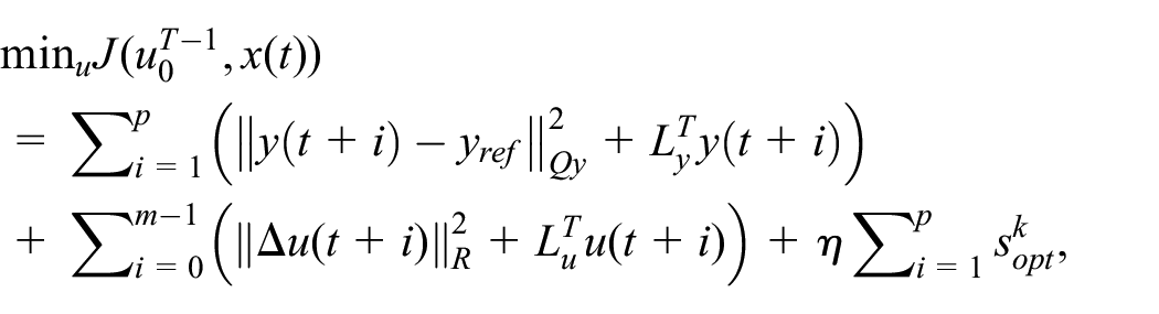
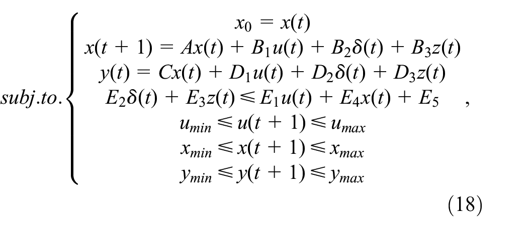
In equation (18),
The control problem shown in the above equation can be reduced to a typical class of mixed-integer quadratic programing problems and solved efficiently by dedicated mathematical software. 26
Design of weighting coefficients self immunity control strategy
From the system control problem, it can be seen that the weighting coefficients have a significant impact on the system control performance. Therefore, this paper further adopts the hybrid model predictive control method of weight coefficient self-immunity adjustment for system damping control strategy design. The control logic of weight coefficient self-immunity adjustment is as follows: when the vibration acceleration is large and the seat suspension travel is small or moderate, the weight coefficients of vertical vibration acceleration should be increased greatly (relatively), and the weight coefficients of the seat suspension travel should be increased slightly; when the vibration acceleration is large and the seat suspension travel is also large, the weights of the vertical vibration acceleration and seat suspension travel should be increased by medium amplitude at the same time; when the vibration acceleration is small, the weights of the vertical vibration acceleration and seat suspension travel should be increased by medium amplitude at the same time. When the vibration acceleration is small or moderate and the suspension travel is large, the weight coefficient of the seat suspension travel should be large and the weight coefficient of the pendulum vibration acceleration should be small; when the vibration acceleration is small or moderate and the suspension travel is small or moderate, the weight coefficients of the pendulum vibration acceleration and the seat suspension travel should be small at the same time so that the effect of the weight coefficient adjustment on the original control can be minimized. The effect of the weighting factor adjustment on the original control is minimized.
In order to obtain the weight coefficients faster, we propose a new method to speed up the updating of the weights of the MIQP problem by using the self-immobilization control strategy, so that the MIQP problem can be solved with faster convergence as well as better performance of the seat suspension control, and the block diagram of the joint control of the MIQP and the self-immobilization control is shown in the following figure:
In Figure 6, the seat vibration signals are collected in real time by the on-seat sensors of the seat suspension system and input to the ADRC processing module, which obtains the real-time optimal state value as the input of MIQP after adaptive optimization search, and then obtains the optimal control input sequence through the calculation of the MIQP solver, and finally controls the variable damping of the shock absorber and adjusts the damper in real time to obtain the best performance.

Schematic of ADRC-MIQP control strategy.
ADRC strategy
ADRC is proposed by Han Jingqing et al.27–29 which is mainly composed of tracking differentiator (TD), extended state observer (ESO) and nonlinear state error feedback (NLSEF). It is mainly composed of Tracking Differentiator (TD), Extended State Observer (ESO) and Nonlinear State Error Feedback (NLSEF), of which TD is mainly used for differential signal acquisition and transition process configuration, ESO is mainly used for total disturbance observation, and NLSEF is used for generating control variables, and the basic structure is shown in Figure 7:

Basic structure of ADRC.
In Figure 7, the disturbance d represents the road profiles, which can be divided into two categories: random road profiles and shock condition road profiles.
For the seat suspension system in this paper, the conversion is shown in the following equation:

In equation (19),
According to Han ’s theory in the references30,31,
The ADRC controller used in this paper employs a second-order dynamic model. In the NLSEF module, the controller bandwidth parameter
Simulation of the control performance of the self-imposed disturbance weighting coefficient
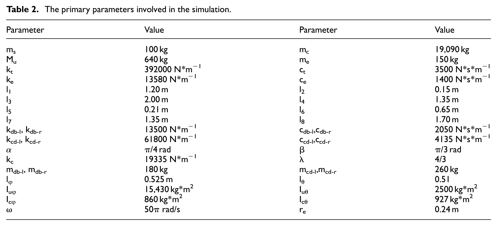
Based on the above control design, to validate the actual control performance of the damping multi-mode switching damper in the wheel loader seat suspension, simulations and analyses of the control system were conducted using passive suspension, Fuzzy-MIQP, and ADRC-MIQP. The simulation conditions assumed the wheel loader traveling at speeds of 8 and 16 km/h on an ISO Class D road profiles, with road excitations considering both random road and shock road conditions. The primary parameters involved in the simulation of the nonlinear wheel loader semi-active suspension seat model with a human body, as illustrated in Figure 5, are presented in Table 2. below.
The primary parameters involved in the simulation.
The results of the simulation of the vertical vibration acceleration of the loader driver and seat equivalent mass at speeds of 8 km/h and 16 km/h are presented in Figures 8 and 9, respectively. The figures illustrate the road profiles at different speeds in the absence of shock conditions.

Comparison of the simulation results of the driver’s vertical vibration acceleration and seat suspension deflection at 8 km/h: (a) ISO Class D road profiles at 8 km/h, (b) Driver’s vertical vibration acceleration at 8 km/h, and (c) Seat suspension deflection at 8 km/h.

Comparison of the simulation results of the driver’s vertical vibration acceleration and seat suspension deflection at 16 km/h: (a) ISO Class D road profiles at 16 km/h, (b) Driver’s vertical vibration acceleration at 16 km/h, and (c) Seat suspension deflection at 16 km/h.
Furthermore, in order to more accurately verify the effectiveness and robustness of the controller, shock conditions are randomly introduced at 8 and 16 km/h speeds. The simulated vertical vibration acceleration results for the wheel loader driver and the equivalent mass of the seat are presented in Figures 10 and 11 for 8 and 16 km/h speeds, respectively.

Comparison of the simulation results of the driver’s vertical vibration acceleration and seat suspension deflection at 8 km/h under shock conditions: (a) ISO Class D road profiles at 8 km/h under shock conditions, (b) Driver’s vertical vibration acceleration at 8 km/h under shock conditions, and (c) Seat suspension deflection at 8 km/h under shock conditions.

Comparison of the simulation results of the driver’s vertical vibration acceleration and seat suspension deflection at 16 km/h under shock conditions: (a) ISO Class D road profiles at 16 km/h under shock conditions, (b) Driver’s vertical vibration acceleration at 16 km/h under shock conditions, and (c) Seat suspension deflection at 16 km/h under shock conditions.
The figures demonstrate that the weight coefficient adjustment control strategy of the ADRC control strategy of the damping mixing model predictive control is more effective than the passive suspension and Fuzzy control mode in altering the weight coefficients. Moreover, the RMS values of the vertical vibration acceleration and seat suspension deflection are presented in Tables 3 and 4, respectively.
RMS values of driver vertical vibration acceleration at different speeds with/without shock conditions.

RMS values of seat suspension dynamic travel at different speeds in the absence of shock conditions.
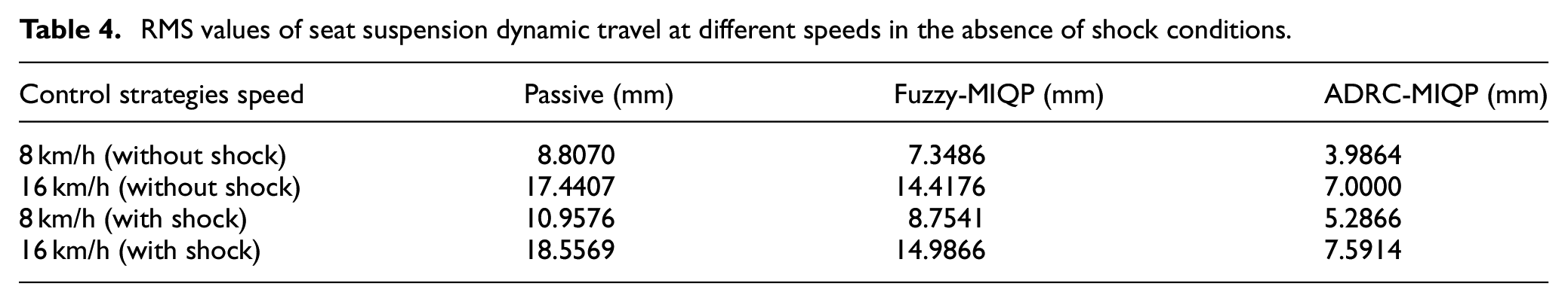
As shown in Tables 3 and 4, at a speed of 8 km/h without shock conditions, the RMS values of vertical vibration acceleration for Fuzzy-MIQP and ADRC-MIQP suspensions decreased by 40.2% and 50.1%, respectively, compared to the passive suspension. At 16 km/h without shock conditions, the reductions were 21.1% and 48.2%, respectively. Consequently, the vibration isolation performance of the wheel loader seat suspension system has been significantly improved, and the ADRC seat suspension system demonstrates good performance at various speeds. However, under shock conditions, at a speed of 8 km/h, the RMS values of vertical vibration acceleration for Fuzzy-MIQP and ADRC-MIQP suspensions decreased by 46.1% and 54.9%, respectively; at 16 km/h, the reductions were 31.1% and 44.5%, respectively. The addition of external shock disturbances did not lead to a decrease in controller performance, reflecting the robustness of the ADRC-MIQP control strategy. In the case of the seat suspension dynamic travel, at a velocity of 8 km/h in a state of no shock, the RMS value of dynamic travel was reduced by 16.6% and 56.7% for the fuzzy-MIQP and ADRC-MIQP suspensions, respectively, in comparison to the passive suspension. The reductions were 17.3% and 59.9% at 16 km/h under no-shock conditions. In the presence of shocks, the RMS values of dynamic travel for the fuzzy-MIQP and ADRC-MIQP suspensions were reduced by 20.1% and 51.8%, respectively, at a speed of 8 km/h, and by 19.2% and 59.1% at a speed of 16 km/h. The RMS values of dynamic travel of the fuzzy-MIQP and ADRC-MIQP suspensions were reduced by 20.6% and 51.8%, respectively, at a speed of 16 km/h. The increase in external shock disturbance did not result in a significant increase in seat dynamic travel, which also reflects the robustness of the ADRC-MIQP control strategy.
The Figures 12 and 13 illustrate the high-speed on-off mode control signals of the multi-mode switching solenoid valves s1 and s2 of the seat suspension damping. From these figures, it can be seen that both the damping control strategy with fixed weight coefficients and the damping control strategy with adaptive adjustment of weight coefficients can achieve direct control of the high-speed on-off mode of the solenoid valve, and the high-speed on-off mode of the solenoid valve does not appear to be switched frequently in a short period of time.
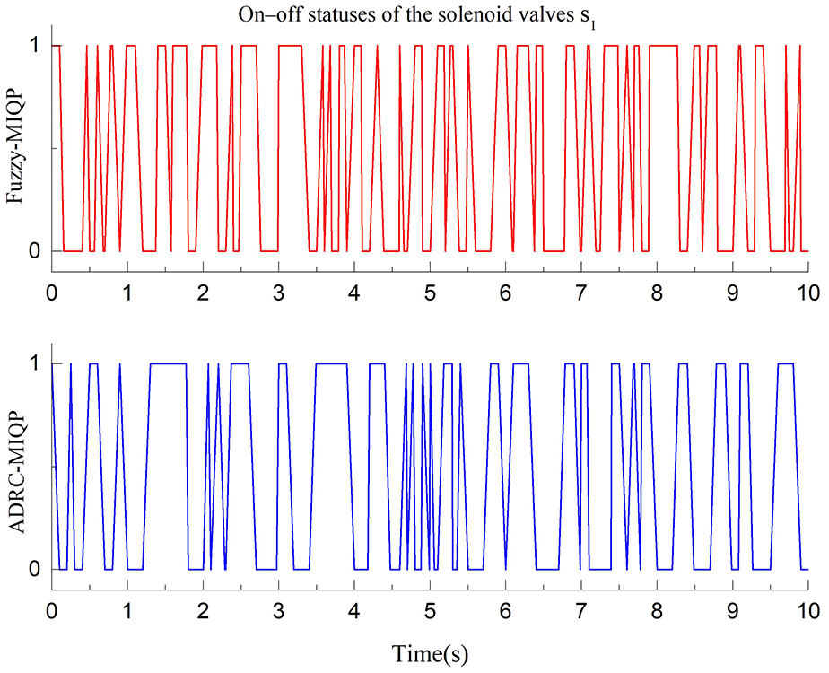
Comparison of control signal simulation results for high-speed switching solenoid valve s1 in on/off mode.
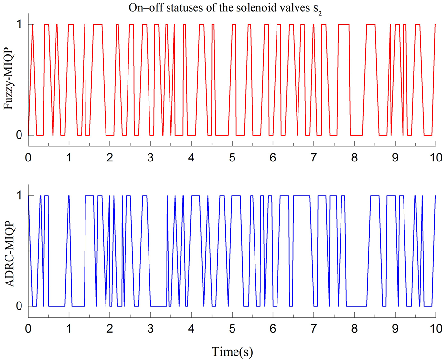
Comparison of control signal simulation results for high-speed switching solenoid valve s2 in on/off mode.
Conclusion
This paper first designed the specific structure of damping multi-mode switching damper based on high-speed switching solenoid valve, on this basis, analyzed the working principle of the damper to achieve multi-mode adjustment of damping, and established a mathematical model of damping characteristics of the damper, combined with the damping model to further master the change rule of damping characteristics of the damper. Then, the damper is applied to the wheel loader seat suspension, and a 10 degrees of freedom mixed logic dynamic predictive model of the wheel loader seat suspension system with multi-mode switching damper is established based on HYSDEL, and the damping control strategy design of the wheel loader seat suspension system is completed by adopting the ADRC control strategy for adaptive adjustment of weight coefficients in the mixed model predictive control method. The simulation results show that the designed damping control strategy of the wheel loader seat suspension system can effectively improve the vibration isolation performance of the system and achieve the expected control objectives of the system.
Footnotes
Handling Editor: Sharmili Pandian
Author contributions
CB and TW discussed and decided on the methodology of the study and prepared the paper. CB contributed to the prototype and test. TW contributed to the model building.
Declaration of conflicting interests
The author(s) declared no potential conflicts of interest with respect to the research, authorship, and/or publication of this article.
Funding
The author(s) disclosed receipt of the following financial support for the research, authorship, and/or publication of this article: The authors would like to thank the Natural Science Foundation of Fujian Province (grant no. 2022J01131963), and Nanping Science and Technology Plan Project (grant nos. N2023Z001, N2023Z002, N2023J001 and NP2021KTS07).