
Abstract
This study aims to demonstrate the synchronous and stable deployment of a newly proposed boom system that consists of cables, a rotary damper, and shape memory alloy with a memorized convex tape shape. Through a shaft, a rotary damper is connected to a reel, and cables wound around the reel are connected to the shape memory alloy boom tips. The deployed part consists of bi-shape memory alloy convex tape booms in which two shape memory alloy convex tapes are combined to form a convex lens cross section, and the outside of the bi-shape memory alloy convex tape is wrapped by a sheet-type heater and polyimide film. The boom is deployed using only the shape recovery force of the shape memory alloy. By installing cables and a rotary damper, the deployment behavior of each boom is controlled, and each boom is deployed synchronously owing to the resistance force of the damper to a leading deploy boom. Moreover, the structural stiffness control concept of the proposed shape memory alloy bi-convex tape boom is discussed considering that Young’s modulus becomes almost half in the martensitic phase.
Keywords
Introduction
For space applications, deployable booms with high packing rate, high bending and torsional stiffness, and low weight are essential. Booms with stable deployment and a simple deployment mechanism are very useful, especially for small satellites because of the limited weight and mounting space. These deployable booms work as actuators for deploying solar array panels and/or membranes, antennas, deorbit membranes, and the like during deployment and serve as structural members after deployment. However, some desired properties of a boom (high packing rate, high bending and torsional stiffness, and low weight) have incompatible characteristics, and it is difficult to satisfy these properties at the desired level. Thus, trade-offs or optimum designs have been considered in developing many types of deployable booms.
Inflatable booms1,2 are considered the best when a high packing rate and low weight are needed. However, it is essential to maintain highly pressurized conditions inside the boom and rigidity of the outer inflatable tube material1–6 to achieve high bending and torsional stiffness after deployment. Storable Tubular Extendable Member (STEM) booms7,8 consisting of tri-axial woven fabric (TWF) carbon fiber–reinforced plastic (CFRP) seem to be one solution for realizing high stiffness after deployment. However, Single-STEM booms7,8 have lower torsional stiffness because of their open cross section. Bi-STEM booms solve the torsional stiffness problem, but they have twice the weight. Booms with a round cross section9,10 or double omega-shaped cross section11–13 have higher bending and torsional stiffness. However, their packing rate is lower than that of other booms because they cannot be slid in their lengthwise direction during packing owing to the tight boundary edge between half round-shaped or omega-shaped sections. This packing condition leads to gaps in the winding roll.
Based on these considerations, the braid-coated bi-convex tape boom (BCON boom14,15) design shown in Figure 1(a) is optimized. In this boom, the combined use of double convex tapes forms an elliptical cross section, and a slidable boundary condition is realized owing to a braid coating. In addition, it can self-deploy by simply releasing the elastic energy stored during packing. As shown in Figure 1(b), the slidable boundary condition in the lengthwise direction realizes a tight winding configuration. The cross-sectional shape of the BCON boom in the packing configuration is rectangular, and this shape recovers to a convex lens shape after deployment. This elliptical cross-sectional shape affords higher bending and torsional stiffness after the deployment of the structural member.

Schematic photo of BCON boom and stored configuration: (a) BCON boom configuration and (b) packed configuration of four BCON booms.
The newly proposed SMA bi-convex tape boom (SMA-BiCon) and SMA braid-coated bi-convex tape boom (SMA-BCON 16 ) also have the same advantages as BCON booms. In SMA-BiCon, an SMA with a memorized convex tape shape is used, and boom deployment is achieved using the shape recovery force of the SMA.17,18 The boom is stored below the reverse transformation start temperature As, and SMA-BiCon can be flexibly bent and packed because of the properties of the martensitic phase in the SMA. The biggest advantage of SMA-BiCon is the flexibility in the overall boom design. For example, as shown in Figure 4, if an SMA-BiCon is wound around a polygonal box satellite, then a partially different boom design is possible. The Bi-SMA convex tape part should be applied to a polygon corner, and a straight and rigid (deformable) boom can be applied to a polygon’s side part. Toward this end, the whole boom must consist of Bi-SMA convex parts and a straight rigid boom part. This design flexibility arises from the simple deployment mechanism of the SMA-BiCon, and partially different boom designs might reduce the weight of the boom design.
Through these structural concept considerations, deployment experiments of SMA-BiCon are conducted in this study. Previous deployment experiments of SMA-BCON 16 have shown that the synchronous deployment of SMA is important to achieve stable deployment behavior. However, it is difficult to control the heating conditions of SMA using a simple heater. Therefore, a simple synchronous deployment mechanism using a cable and rotary damper is developed, and synchronous deployment is demonstrated. Moreover, the combined concept of SMA and shape memory polymer (SMP) is discussed with the aim of maintaining high bending and torsional stiffness after deployment and under martensitic phase conditions of the SMA.
SMA-BiCon
A conceptual model of the SMA-BiCon is shown in Figure 2. Figure 2(a) shows the SMA convex tape. The SMA material consists of a Ti-Ni alloy (Ni: 55 wt%). The temperature of As is set as 60°C. The memorized shape is a convex tape. Figure 2(b) shows the conceptual model of SMA-BiCon. The upper figure shows the actual manufactured boom, and the lower figure shows the cross-sectional configuration. As described in section “Introduction,” the boom consists of two parts: the bendable and deployable SMA part and the straight lightweight boom part. The latter is made of a punched acrylic plate. The former consists of three layers. The SMA convex tape is located in the innermost layer, and the sheet-type heater is located on the outside of the SMA. This heater material consists of a daily-use food wrap film (polymethylpentene) and a Carbo e-Therm Heater layer. Carbo e-Therm is a type of paint that contains carbon powder. After spreading Carbo e-Therm on the film, the film works as a heater when current is supplied. We manufactured the heater part ourselves. The outermost layer consists of a polyimide tape wrapping that works as an insulation material and increases the heating effect of the inner side.

SMA-BiCon material and SMA-BiCon conceptual model configuration: (a) SMA convex tape and (b) SMA-BiCon configuration and schematic illustration of SMA-BiCon cross section.
Synchronous deployment system
Under a power supply of 1 W, the sheet-type heater heats up and the SMA-BiCon gradually deploys, although the heating condition of the each SMA convex tape is independent. To control the electric power supply, the same power is supplied to each heater; however, the each SMA convex tape does not show a synchronous deployment behavior owing to its contact condition and heater and/or individual heat sensitivity differences of the each SMA convex tape. Through trial-and-error examinations, another synchronous deployment method for the SMA-BiCon was developed using cables and a rotary damper.
Figure 3 shows the outline of the synchronous deployment system, and Figure 4 shows the schematic illustration of the deployment behavior of this system from top view. The boom tips and center shaft are connected through cables (nylon fibers is used in this demonstration), and the center shaft and rotary damper are connected through gears. If one boom deploys earlier than the other booms, the quick deployment behavior is interrupted by the damping force from a common rotary damper, and the interrupt force acts to the boom through the cables. This system is still in the concept phase, and the cables and rotary damper system will be further simplified and made more lightweight in an actual space mission design. To measure the rotational angle and angular velocity, a rotary encoder and a gyro sensor are also installed in this device. A thrust bearing is located at the bottom of the box for free rotational conditions.

Outline of synchronous deployment system.

Schematic illustration of the deployment behavior of synchronous deployment system: (a) packed configuration, (b) configuration after the first step of deployment, and (c) configuration after the second step of deployment.
Deployment experiment
Experimental device
Figure 5 shows the configuration of the experimental device after the first step of deployment. In this study, SMA-BiCon has two deployment parts, and these are contained within a square box with dimensions of 300 mm × 300 mm × 150 mm. The direct current (DC) power supply is located under the box, and it supplies the heater current. The booms deploy in a stepwise manner. It is possible to heat every deployment part and to deploy every boom simultaneously; however, stepwise deployment is performed in this experiment to demonstrate the synchronous deployment system for various boom lengths.

Experimental device after first step of deployment.
Experimental results
The deployment experiment is examined for supplied voltages of 7.5 and 10.0 V. The deployment behavior is recorded using a video camera, and the deployment percentage is calculated from the captured photographs. The captured photographs are obtained at 1-s intervals. The deployment percentage is defined as follows: deployment percentage = deployment angle (°)/90 (°). The deployment angle is measured from the captured pictures using image-processing software. Booms 1–4 are set as shown in Figure 6(a) and (b). After the first step of deployment, the stored boom position rotates by 90° clockwise, and the number of booms is set in this manner. The center body angular velocity value is obtained using the gyro sensor. The z-axis body angular velocity value, indicated by yellow arrows in Figure 5, is compared in this study.

Example of deployment behavior with cables and rotary damper system: deployment behavior in (a) first step and (b) second step.
Figure 6 shows the images of deployment with the synchronous deployment system, and Figure 7 shows the boom deployment percentage and center body angular velocity results for supplied voltages of 7.5 and 10.0 V. In the same way, Figures 8 and 9, respectively, show images of the deployment without the system and the boom deployment percentage and center body angular velocity results. The graphs are divided into two parts that show the deployment results after the first and second steps.

Boom deployment percentage and center body angular velocity value with cables and rotary damper system: supplied voltage of (a) 7.5 V and (b) 10.0 V.

Example of deployment behavior without cables and rotary damper system: deployment behavior in (a) first step and (b) second step.

Boom deployment percentage and center body angular velocity value without cables and rotary damper system: supplied voltage of (a) 7.5 V and (b) 10.0 V.
Discussion
From a comparison of Figures 6 and 8, the effect of the synchronous deployment system is clear, and the synchronous deployment behavior is well demonstrated. Compared to Figures 7 and 9, the deployment percentage of each of the four booms is the same, and synchronous deployment can be confirmed from the graph. The angular velocity with the cables and rotary damper system is almost one-half of that without the system. The angular velocity shows peaks immediately after the completion of deployment or after a quick deployment phase. The graph in Figure 9(a) clearly shows the relation between the angular velocity peak and the final phase of deployment, and that in Figure 7(a) shows the relation between the angular velocity peak and the deployment speed. The deployment of each boom completes quickly in ∼85 s in Figure 7(a), but one angular velocity peak is observed because of the synchronous deployment. Although boom deployment without the system, as shown in Figure 9(a), is independent, and boom 4 (yellow line) and boom 2 (blue line) complete the deployment quickly, many angular velocity peaks are observed and boom deployment becomes unstable. From these considerations, it is found that synchronous and uniformly low-velocity deployment is the key to realizing stable deployment.
Conclusion and future work
In this study, new types of deployable booms consisting of SMA bi-convex tape are proposed, and to realize stable synchronous deployment, a synchronous deployment system consisting of cables and rotary dampers is also proposed. Through deployment experiments using a conceptual model, synchronous deployment behavior is achieved compared to the model without the system, and stable deployment is also achieved as demonstrated through comparisons of the angular velocity during deployment.
From the viewpoint of the bending and torsional stiffness after deployment and below the martensitic transformation completion temperature, the martensitic-phase SMA has Young’s modulus that is almost one-half that of austenitic phase SMA. The important function of a deployable boom is to serve as a structural member that maintains the shape of a panel or a membrane after deployment. The combined use of SMA and SMP solves the problem of reduced structural rigidity. We plan to design SMA- and SMP-layered convex tape booms, as shown in Figure 10, and to investigate their bending and torsional stiffness and natural frequency under different temperature conditions.
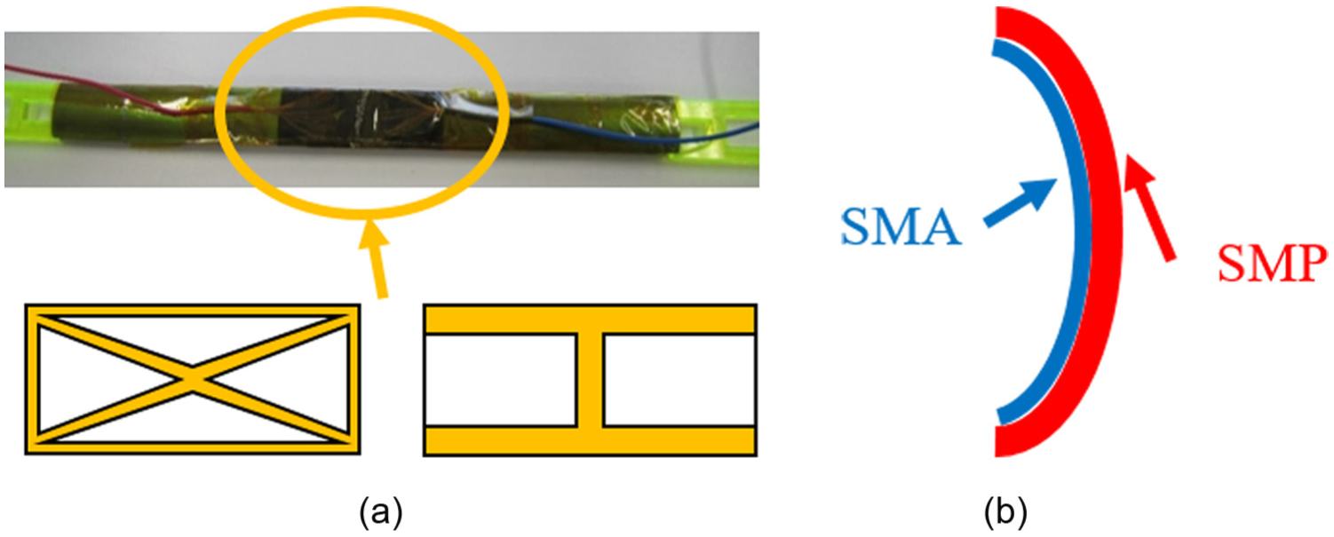
Combination of SMA and SMP for realizing SMA-BiCon boom: (a) SMP sheet shape and (b) cross section with combination of SMA and SMP layers.
Footnotes
Academic Editor: Hamid Reza Shaker
Declaration of conflicting interests
The author(s) declared no potential conflicts of interest with respect to the research, authorship, and/or publication of this article.
Funding
The author(s) disclosed receipt of the following financial support for the research, authorship, and/or publication of this article: This work was supported by JSPS KAKENHI (grant number: 15K18280).