
Abstract
Circumference radial preload due to the interference fit is of a great significant influence on rolling frictional power loss of bearing and service life of machinery. In this article, an analytical method where circumference radial preload is first involved is presented for determining the value of rolling friction power loss of ball bearing (SKF-6205). The experiments under different operating conditions for the bearing were carried out which verify the validity of our proposal. The work described in this article can be regarded as a foundation for the accuracy thermal modeling and friction power loss analysis of the deep-groove ball bearings in machinery.
Introduction
Deep-groove ball bearing was widely used to support rotational shafts in machine due to the low friction properties associated with it. 1 Whereas the circumference radial preload (CRP) generated due to the interference fit has a significant influence on the bearing frictional power loss and service life of machine. It is well known that the assembly accuracy of bearing is crucial in design of rotational machinery system. When external preload is large enough, rolling friction would play a leading role in bearing friction. A great deal of research work has been done on the rolling element bearing preload almost in the axial and radial directions or combination of them.2–4 According to Hertz elliptical contact theory, the CRP has a direct effect on the bearing’s deformation and contact force between the balls and bearing raceways. A three-dimensional finite element method was proposed to simulate the friction properties for large-sized deep-groove ball bearings whose surfaces were coated with thin lubricant film using Hertz contact theory. 5 With respect to the motion analysis of the ball’s rolling and sliding during the ball’s orbit motion in the raceways, some attempts, such as by Alexandre and Daniel 6 and Hamrock, 7 have been made. Moreover, Kang et al. 8 presented modified load–deflection factors iterated using the Newton iterative algorithm to make the deviations of the results of Jones–Harris method be significantly reduced or eliminated for the deep-groove ball bearings.
In this article, taking the deep-groove ball bearing (SKF-6205) as a case, we first analyze bearing circumference deformation resulting from the CRPs. Subsequently, an analysis of the bearing motion is done to calculate the contact frequency for the balls. Moreover, a load distribution model due to CRPs between bearing and bearing housing would be developed to analyze the variation in the bearing frictional power loss. Ultimately, a dynamic model of frictional power loss for the deep-groove ball bearing is built based on energy approach. To verify the theoretical formulations, extensive experiments are carried out under different CRPs and rotational speeds.
Circumference deformation
Circumference deformation due to the interference fit
The deformation generated in the bearing due to the CRPs between the bearing outer ring and bearing housing or bearing inner ring and shaft could be the main factor for the variation in bearing frictional torque. According to the analytical method described in Elastic mechanics, 9 the deformations u1 and u2 which simultaneously occur in the both edges are, respectively, written as


where p1, p2, E, ν, R1, R2, and r represent the pressure in the inner ring, the pressure in the outer ring, the elastic modulus, the Poisson’s ratio, the radii of the inner and outer edges of the ring, and the radius from the micro-element to the center of the ring, respectively. The minus denotes the direction of deformation pointing to the ring’s center.
The deformation of a ring subjected to the internal and external pressures can be applied to the bearing with an interference fit. Due to the bearing inner ring’s expansion and the deformation, δi in the radial direction is

where d, D, Δf, Δf′, p1, and Di denote the diameter of the bearing inner ring, the diameter of the bearing outer ring, the assemblage excess between the shaft and bearing inner ring, the assemblage excess between the bearing housing and bearing outer ring, the internal pressure generated in the bearing inner ring, and the equivalent diameter of inner ring, respectively.
Nevertheless, when the interference fit is employed between the bearing outer ring and bearing housing, the bearing outer ring will be shrunk. The deformation δe in the radial direction is

where EB, p2, and de, respectively, denote the elastic modulus of bearing housing, the external pressure generated on the bearing outer ring, and the equivalent diameter of the bearing outer ring.
However, p2 as the CRP applied on the bearing outer ring can be given by an apparatus which will be described in the later section.
Contact load
According to the Hertz 10 contact theory, we can obtain the relationship between the total applied load and deformation in bearing as follows

where K, δ, and QT, respectively, denote the load–deformation factor, the magnitude of total deformation, and the total applied load. The load–deformation factor K for point contact can be expressed as

where Ki and Ke, respectively, denote load–deformation factors between the ball and the bearing inner raceway and outer raceway, which can be acquired in a table in Deng and Jia. 11
Rolling friction
Contact frequency
To analyze the motion relationship between the balls and raceways, a fixed coordinate system xyz and a float coordinate system x′y′z′ are, respectively, established for the bearing and the balls as shown in Figure 1.

Bearing rotating with fixed outer raceway, ne = 0 r/min.
It can be seen in Figure 1 that the outer raceway is fixed, and therefore, the rotational speed ne equals zero. According to the non-slip condition, the velocity VA at contact point between the ball and the inner raceway can be calculated by

where ni, dm, and Db denote the inner raceway rotational speed, the bearing pitch diameter, and the diameter of the ball, respectively. The variable α = Db/dm. Since the bearing outer raceway is fixed, velocity VB at the contact point between the ball and the outer raceway equals zero. Therefore, the contact frequency for the balls and the inner raceway Ii can be calculated by

Similarly, the contact frequency between the balls and the outer raceway Ie is given as

Therefore, the total contact frequency for all balls moving between the inner and outer raceways I is given as

Point contact
According to Hertz contact theory, the shape of contact surface is an ellipse when the ball contacts with the raceways. Moreover, surface contact pressure is distributed in ellipsoid form as shown in Figure 2. The expressions of point contact parameters are listed as follows 11

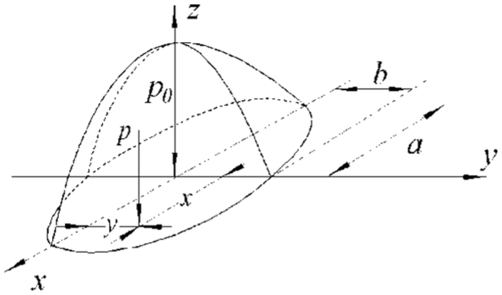
Hertz point contact.
where a, b, P0, and P denote the semi-major axis, the semi-minor axis, the maximum pressure on the center of the contact region, and the arbitrary pressure on the contact region; na and nb are the coefficients associated with main curvature difference function F(ρ), which can be obtained in a list in Deng and Jia. 11
Elastic hysteresis
When the ball rolls between the raceways, the front and back pressures distribute asymmetrically around the contact region that the front contact pressure is larger than the back one. Therefore, there is a resistance moment in the rolling direction of the ball. From Figure 2, pressure dQT on the micro-belt dy with a distance y to x-axis is

The moment Mx due to the pressure on the semi-ellipse (0 ≤ y ≤ b) is expressed as

When the ball rolls a unit arc length, the work done by Mx is
Due to the elastic hysteresis, the work done by the back pressure (−b ≤ y ≤ 0) is smaller than the W done by the front pressure because of the asymmetric pressure distribution. The difference value between the works done by the front moment and back moment is the energy dissipation ΔW. In view of the complexity of the actual pressure distribution, an elastic hysteresis dissipation coefficient αh is introduced. Therefore, the energy dissipation ΔW can be written as

where the value of αh can be acquired in Guo. 12
As a consequence, when all the balls that are subjected to the applied load QT are rolling between the inner and outer raceways, the total energy dissipation WT is expressed as

Considering the other friction recourses, for example, sliding effect in the curved surfaces of ball–race contacts and other micro sleeps which are considered a variable Mdrag which is a function of bearing speed. 13 Therefore, the rolling friction power loss Tloss can be given as

where Z and Db represent the total number of balls in one bearing and the diameter of the ball, respectively.
Experiments and verification
Experimental apparatus
To verify the theoretical results, SKF-6205-2Z/C3 deep-groove ball bearing used in the experiment was studied. The elastic modulus of the bearing material (GCr15) is 217 GPa and the Poisson’s ratio ν is 0.3. The bearing is lubricated by no. 2 lithium base grease. Table 1 shows the specifications of the bearing.
SKF-6205 deep-groove ball bearing parameters.

In Table 1, D and d denote the diameters of the bearing outer ring and inner ring, respectively. dm is the bearing pitch diameter and B is the bearing width. Db and Z are the diameter of the ball and the number of the balls, respectively. The test bench as shown in Figure 3(a) is mainly composed of drive motor, torque transducer, load chuck, and computer. It can be seen that the drive motor as drive unit is connected to the torque transducer by a coupling. When bearing torque varying due to the CRP is applied on bearing, the torque transducer will record the torque value in time and display it on the computer screen. As shown in Figure 3(b), the load chuck consists of three high-strength springs, three fan-shaped blocks, three load bolts, crosshair frame, adjustable base, and circle frame. By adjusting the three load bolts, the preload approximated to circumferential load can be applied on the surface of the bearing outer raceway. The pressure sensor mounted on the top fan-shaped block as shown in Figure 3(a) can record and display the load value of one bolt. The total CRP is three times the load value of one bolt. For investigating the relationship between CRPs applied on the bearing outer ring and the bearing frictional power loss, a transitional fit (H6/m5) was employed between the shaft and the bearing inner ring. Because of the transitional fit (H6/m5), relative to external pressure p2, the internal pressure p1 was too small to be neglected.
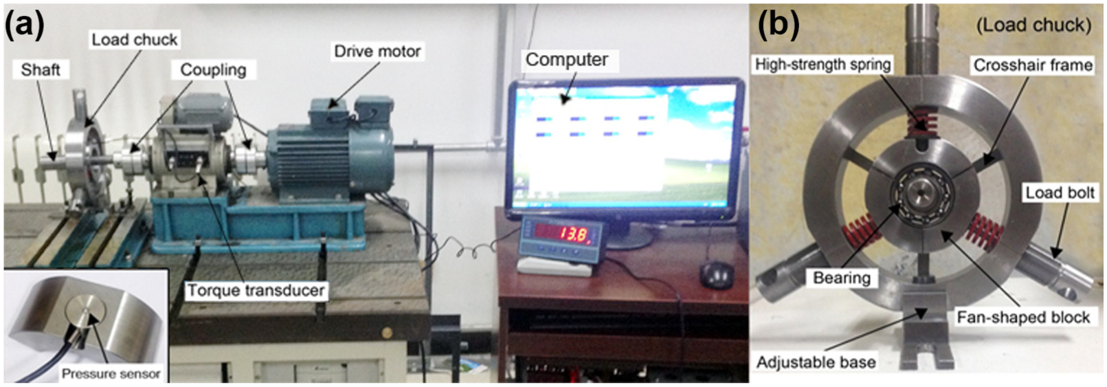
(a) Bearing torque test bench and (b) loading chuck.
Verification
From the experimental results as shown in Figure 4, it can be seen that the value of torque for bearing without lubrication is smaller than for bearing with lubrication in every test point. During the low-speed range, the difference between the two curves is small. With the rotating speed of the bearing inner ring increasing, the difference would be enlarged due to grease churning. As the speed continues to increase, the difference becomes small because most grease is pushed out. Moreover, it can be seen that the two fitting curves for the experiment are nonlinear. From the experimental results as shown in Figures 5–7, it can be seen that in these charts, with CRP increasing, differences between the two experimental fitting curves get smaller and smaller. Moreover, the deviation between theoretical curve and experimental curves becomes larger and larger. The experiments for the bearing under different CRPs with three speeds were carried out. Figure 8 shows the experimental results. Obviously, there is a lowest value of bearing power loss at one CRP point under three different rotational speeds due to the occurrence of plastic deformation. In other words, theoretical method could be valid under a condition that the largest Hertz contact pressure is less than 3.1 times yield shear stress. 14 It can be seen in Figure 8 that as the rotational speed increases, bearing power loss increases.

Bearing power loss at different speeds with CRP (0 N).

CRP = 5000 N.

CRP = 8000 N.

CRP = 11,000 N.

Bearing torque under different CRPs.
Conclusion
This work develops a theoretical method based on elastic mechanics and Hertz contact theory to analyze the frictional power loss associated with a deep-groove ball bearing (SKF-6205) under different CRPs and rotational speeds. Compared with the experimental results, the results show that the model is reasonable and valid under the range of low CRP. Several conclusions are arrived at by comparing the analytical results with the experimental results:
Frictional power loss of deep-groove ball bearing with lubrication is always larger than that of bearing without lubrication. When CRP equals zero, the bearing power loss curve is nonlinear.
Experimental results show that when CRP exceeds a certain value, bearing rolling frictional power loss will increase significantly in the bearing total frictional power loss and the curve will be linear. Whereas with the CRP increasing, the deviations between theoretical curve and experimental curve increase.
Once the CRP exceeds the value where the bearing plastic deformation occurs, the bearing frictional power loss will greatly decrease.
Footnotes
Academic Editor: Michal Kuciej
Author Note
All authors are now affiliated to Beijing Institute of Exploration Engineering, No. 29 College Road, Haidian District, Beijing City, P.R. China.
Declaration of conflicting interests
The author(s) declared no potential conflicts of interest with respect to the research, authorship, and/or publication of this article.
Funding
The author(s) disclosed receipt of the following financial support for the research, authorship, and/or publication of this article: The work was supported by the international technology cooperation and exchanges program (3500m permanent magnet direct-top driver geological drilling rig), grant no. 2015DFA70300.