
Abstract
Radial load is of great significant influence on friction characteristic and fatigue life of rolling bearings. A frictional torque analysis was performed on the radially loaded SKF-6205 deep-groove ball bearings. The frictional torque formula was proposed as the sum of the frictional torques caused by elastic hysteresis, elastic hydrodynamic lubrication, differential slip, spinning friction of balls, friction between the balls and the cage pockets, and friction between the cages and the guiding lands. The experiments were carried out with the bearing with lubrication and the other one without lubrication under different radial loads and rotational speeds. In order to avoid the frictional torque measurement errors caused by the unequal length of arms, a positive–negative test method is employed to test bearing frictional torque. The experimental results showed that the frictional torque caused by radial loads played a leading role in all the frictional torque components of the bearing. Ultimately, a special theoretical model of frictional torque for deep-groove ball bearings was verified through comparing with the experimental results and SKF torque model. A reasonable correlation exists between the experiment results and the theoretical model.
Introduction
Rolling bearings have been used widely in rotational machinery due to the low friction property. Frictional torque as an important technical indicator used to assess the performances of a bearing is getting more and more focus in the bearing application fields. Since the 1950s, frictional torque of rolling bearings began to attract extensive attention worldwide. SKF researchers developed a friction torque model for the deep-groove ball bearing, which is well accepted and globally used. 1 As to frictional torque analysis and calculation of rolling bearings under different loads in radial or axial direction and lubrication conditions, some researches had been done as presented in previous studies.2–7 Moreover, Aramaki et al. 8 investigated the characteristics of ball bearings with silicon nitride ceramic balls in high-speed spindles for machine tools. Liao and Lin 9 investigated the bearing’s skidding under different axial and radial loads. Leblanc and Nelias 10 analyzed the motion of the balls and sliding friction in a four-contact point ball bearing. In addition, frictional torque of the bearings in wind generation and variable pitch system was analyzed and a test rig was developed to test friction characteristics of this type of bearings. 11 Sim et al. 12 investigated the effects of preloads and bearing clearances on the rotor dynamic performance of lobed gas foil bearings for the oil-free turbochargers. Wang and Yuan 13 analyzed contact force distribution and static load-carrying capacity of the large size double-row four-point contact ball bearing. Li et al. 14 developed a frictional torque test apparatus for high-speed micro ball bearings and proposed a calculation formula. Savaşkan and Maleki 15 performed experiments to investigate the friction and wear properties of Zn-25Al-based bearing alloys. Brecher et al. 16 investigated the effects of cage friction in the high-speed spindle bearings and proved that the frictional torque caused by cage friction could not be neglected in the analysis of bearing friction resistance. With respect to the investigations on the bearing with defects, Shaha et al. 17 carried out a lot of experiments and indicated the correlation between the frictional torques and the different size defects. Through analyzing the above researches, the load applied on the bearings in radial direction as the most common loading way is of significant influence on the frictional torque of rolling bearings.
In this article, taking SKF-6205 deep-groove ball bearing as a case, stress and strain of the bearing subjected to radial loads are analyzed. Subsequently, a model of frictional torque caused by elastic hysteresis is built. Moreover, the other frictional torque sources due to elastic hydrodynamic lubrication (EHL), differential slip, spinning friction of the balls, friction between the balls, and the cage pocket and friction between the cage and the guiding lands are investigated. Finally, a total frictional torque formula for the deep-groove ball bearings is proposed. In addition, a test apparatus is developed and the experiments are carried out with the bearing with lubrication and the other one without lubrication under different radial loads and rotational speeds. Furthermore, in order to verify the validity of the proposed frictional torque formula, a comparison of the calculated results with the measuring results is carried out. Ultimately, some conclusions are summarized in the last section.
Frictional torque formulae of the bearing subjected to radial loads
It is well known that the precise calculation of bearing frictional torque is difficult due to the complex property of friction occurring in the bearing motion. According to Deng and Jia, 18 bearing frictional torque can be divided into six components which include the friction caused by elastic hysteresis, EHL, differential slip, spinning sliding, friction between the balls and cage pocket, and friction between the cage and guiding lands. Whereas the component of frictional torque caused by elastic hysteresis of the material plays a leading role in all the friction components of the bearing subjected to radial loads. Through investigating the six friction components, finally, a special theoretical model of the total frictional torque for the deep-groove ball bearings is built.
Stress analysis of the bearing subjected to radial loads
This part comprises the analysis of stress and strain for the bearing under radial loads and formula derivation of the bearing frictional torque caused by elastic hysteresis.
Stress and strain analysis of bearing under radial load
Bearing loaded in radial direction is the most common loading way, as shown in Figure 1.

Bearing (a) before and (b) after being loaded.
It can be seen in Figure 1(a) that there is a clearance ur/2 between the top point of the ball and the groove of the bearing outer ring when there is no load being loaded on the bearing. However, when the load is applied on the bearing as shown in Figure 1(b), the center displacement of the bearing inner ring in vertical direction δr is
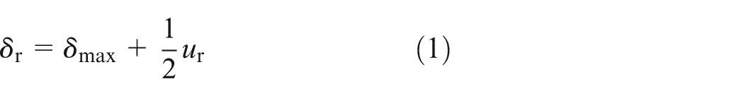
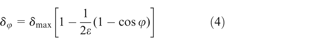
where δmax denotes the deformation of the ball at the bottom. According to deformable coordination conditions, the contact deformation δφ of the ball at arbitrary angular position φ can be determined by

To simplify the δφ, letting

Equation (2) becomes
When δφ = 0, the limit angle of load distribution φl is

Therefore, when radial clearance ur > 0, ε < 0.5 and φl < 90°, that is, the loading zone is less than 180°. According to Hertz contact theory, the formula representing the relationship between the load and the deformation is expressed as

where Qi(e),j, K, and δi(e),j represent the contact load of the jth ball, deformation–load coefficient, and deformation of the jth ball, respectively. The subscripts i and e refer to the inner ring and the outer ring, respectively. In terms of equation (6)

where Qi(e),φ and Qi(e),max denote the contact load of the ball at the φ position and the bottom, respectively. Therefore

And the equilibrium equation of the inner ring can be expressed as
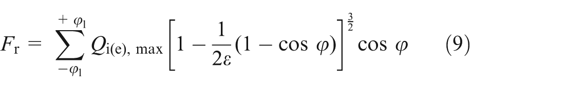
The approximate integral format of the above equation is as follows

By substituting equation (10) into equation (8), Qi(e),max is expressed as follows
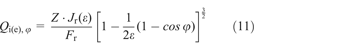
where Jr(ε) is the radial integral of load distribution given by

The value of Jr(ε) based on the value of ε can be obtained from a table in Deng and Jia. 18
Frictional torque caused by elastic hysteresis
When the ball rolls between the raceways, there will be a resistant torque due to the elastic hysteresis of the material. Therefore, when the jth ball experienced an entire loading loop, the energy loss caused by elastic hysteresis can be determined by 19
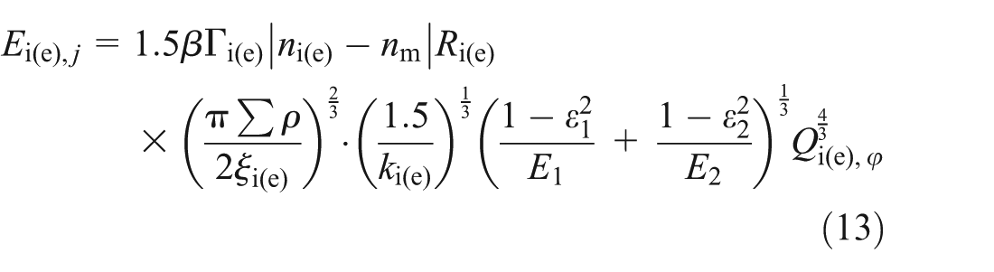
where β is the elastic hysteresis loss factor, which is about 0.007 for the bearing steel. ni(e) and nm are the rotational speeds of the bearing inner ring or outer ring and the revolution speed of the ball, respectively. E1 and E2 are the elastic modulus for the ball and bearing rings. ki(e) = ai(e)/bi(e) denotes the ellipse ratio. Where ai(e) and bi(e) are the semi-major axis and semi-minor axis of the elliptical contact area, respectively. Ri(e),j denotes the distance between the contact point and the rotational axis of the ball. Γi(e) and ξi(e) represent the first and second kinds of complete elliptic integrals, respectively.
According to the principle of energy conservation, the formula of frictional torque MH caused by elastic hysteresis is expressed as

Frictional torque caused by other sources
Except for the frictional torque due to elastic hysteresis, the other sources of frictional torque of bearing including frictional torque caused by EHL, differential slip, spinning friction, friction between balls and cage pocket, and friction between the cage and the guiding lands will be investigated. Accordingly, formulae about these components of bearing frictional torque will be deduced and given referring to the previous research.
Frictional torque caused by EHL
When the bearings are lubricated by grease or oils, the viscous shearing resistance between balls and raceways will generate a frictional torque to resist the ball’s movement, especially at the high rotating speeds. The energy loss due to the viscous shearing resistance can be determined by 19

where d is the thickness of oil film. η and p denote the kinematic viscosity of mineral oil and the pressure of contact area, respectively. v1 and v2 represent the velocity of balls and raceways at the contact point, respectively.
According to the principle of energy conservation, the formula of frictional torque ME caused by EHL is expressed as

Frictional torque caused by differential slip
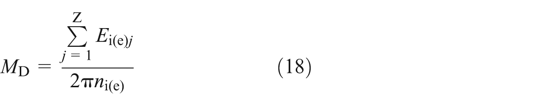
When the balls roll in the groove with a certain radius in a plane perpendicular to the direction of rolling, pure rolling occurs along two lines on the ellipse of contact. In the other parts of the ellipse, differential slip occurs due to the unequal distance of contact point from the axis of rotation. The energy loss of the frictional torque caused by differential slip can be determined by 19

where μD, νηξ, and Ω denote the coefficient of friction between the balls and raceways, the relative difference of velocity between the balls and raceways on the direction of sliding on the contact area, and the ellipse contact area due to the deformation of elastic contact between the loaded balls and the raceways, respectively.
According to the principle of energy conservation, the formula of frictional torque MD caused by differential slip is expressed as
Frictional torque caused by spinning friction
When the center line of the bearing inner ring is not parallel to the horizontal lines, spinning of the balls occurs due to an angle θ between the center line of the bearing inner ring and the horizontal lines, which results in a friction to resist the rotational motion of balls in the plane perpendicular to the normal lines of the balls. Because of the spinning friction, the energy dissipation due to that will make the bearing temperature rise. Referring to the previous research work, the frictional torque caused by the spinning friction can be determined by 19
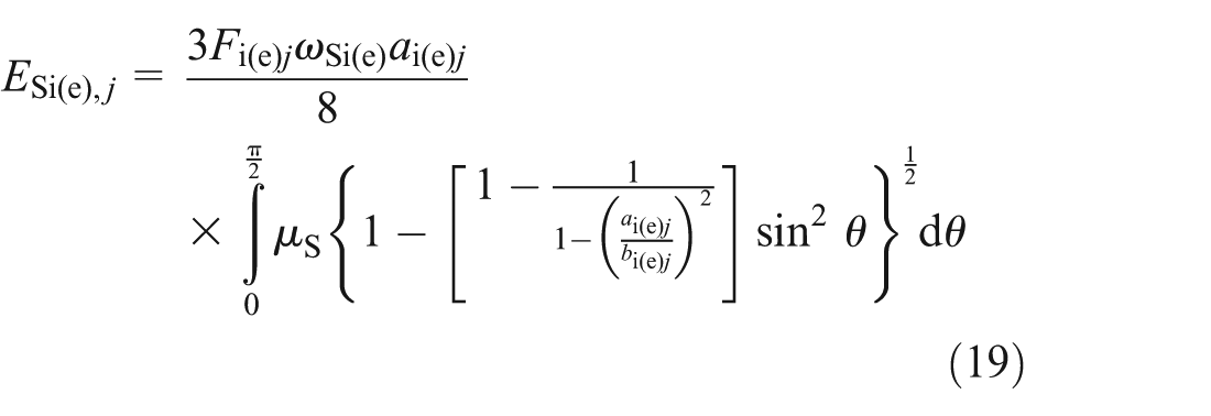
where ωSi(e) and μs denote the spinning component of the balls when they roll between the raceways and the friction coefficient of spinning between the balls and raceways, respectively.
According to the principle of energy conservation, the formula of frictional torque MS caused by spinning friction is expressed as

Frictional torque caused by friction between balls and cage pockets
When the balls rotate in the cage pockets, the friction between the balls and the cage pockets will occur which will resist the rotation of the balls. According to the principle of energy conservation, the energy dissipation caused by the friction between the balls and the cage pockets equals the energy loss due to the bearing frictional torque MC in the unit time. Referring to Deng, 19 thus, the frictional torque MC is expressed as

In unit time, the energy dissipation of sliding friction ESj and rolling friction ERj of the jth ball are, respectively, expressed as follows


where αh is the material elastic hysteresis factor. When the fluid in the inlet of the contact area between the balls and cage is pumped into the contact surfaces, FSξj and FSηj are the sliding resistances on the surfaces of balls generated by the pump suction effect of the fluid. FRξj and FRηj are the rolling resistance. 19
Frictional torque caused by friction between cage and guiding lands
The frictional torque caused by the friction between the cage and the guiding lands on bearing rings is the smallest component in all the components of the frictional torque compared with others. According to the principle of energy conservation, the frictional torque ML caused by the friction between the cage and the guiding lands is expressed as 19

where Mcx denotes the frictional torque on cage surface generated by the hydrodynamic pressure oil film and ωc is the angular speed of cage.
Total frictional torque formulas
By analyzing each frictional torque component of deep-groove ball bearing, the formula of each component is deduced as mentioned above. Ultimately, a special theoretical model for the deep-groove ball bearings is given as follows

Discussion
As mentioned above, the rolling bearing frictional torque consists of six components that include the frictional torque caused by the elastic hysteresis of material, the EHL, the differential slip, the spinning friction, the friction between the balls and cages, and the friction between the cages and guiding lands. However, every component has a different influence level on the bearing frictional torque. Figure 2 shows the theoretical results of the total frictional torque and the six frictional torque components of the SKF-6205-2Z/C3 deep-groove ball bearing under the radial load of 50 N and rotational speeds of 0–2000 r/min. The elastic modulus of the bearing material is 217 GPa and Poisson’s ratio ν is 0.3. The dynamic viscosity of lubricant is 160 cSt (40 °C).

Theoretical results of deep-groove bearing frictional torque.
It can be seen from Figure 2 that when the rotational speed is less than 700 r/min, the elastic hysteresis of material MH and the spinning friction MS are the main influent factors to the bearing frictional torque. Moreover, the sum of the percent of MH and MS is about 90% in the low-speed ranges of 0–700 r/min. With the rotational speed increasing, the lubrication film between the balls and the raceways is gradually formed, which results in the frictional torques ME and MC increasing. Because of the presence of the oil film which decreases the frictional coefficient between the balls and raceways, the frictional torques MD decrease to the lowest point at the speed of 1600 r/min. When the rotational speed exceeds 2000 r/min, the frictional torques MS and MD are the main influence factors to the bearing frictional torque. And the percent of ME continuously increases with the rotational speed increasing. In addition, the frictional torque MC and ML increase slowly with the rotational speed increasing in the high-speed ranges. Therefore, for the bearings applied in the low-speed ranges, the design points of bearings are the stiffness of the material and the structure of the raceways. However, for the bearings applied in high-speed ranges, the design points of bearings are the lubrication performance, the thermal conductivity of materials, and the weight of rolling elements.
Experiments and verification
The research work on frictional torque test apparatus for the bearings under radial or axial loads has always been a hot research topic.20–28 Through summing up the experiences of previous research, this article presents a new test apparatus based on a lathe with frequency converter. Taking the SKF-6205-2Z/C3 deep-groove ball bearing as a case, the experiments for the bearing with lubrication and the other one without lubrication under different radial loads and rotational speeds were carried out. In order to verify the validity of the theoretical formula proposed in previous section, the comparisons of the theoretical results with the measured results and SKF torque model are performed.
Apparatus and test method
The test apparatus as shown in Figure 3 consists of a loading device, two pressure sensors, and a lathe with a frequency converter. The loading device uses a flexible loading way to the bearing outer ring by virtue of the high-strength springs and the threads. Moreover, the lathe with a frequency converter is able to control the speed in the range of 0–2000 r/min.

Bearing frictional torque test apparatus.
As shown in Figure 4, the signal acquisition system is composed of pressure sensors, signal amplifiers, data acquisition card, and computer. When the pressure signals are obtained from the sensors, two signal amplifiers are needed to filter and amplify the signals. The data acquisition card converts the analog signals from the amplifiers into digital signals and transmits them to the computer which will record and display the digital signals by a USB communication port. In order to measure the bearing temperature during the test process, an infrared thermometer was employed.

Signal acquisition system.
The loading device as the key part in the test bench is shown in Figure 5. Considering the influence caused by the interferential fit employed between the bearing outer ring and the chuck inner ring, the chuck is divided into two parts (chuck 1 and chuck 2) which are connected by two M × 6 bolts. Moreover, two triangle grooves are located symmetrically on the bottom of chuck 1 to match the two struts which are connected with two sensors by threads. The top of the slider is connected to the bottom of the sensor and the rest passes through the chambers of the high-strength spring and the loading nuts to make the sensor can move in the vertical direction. The two loading nuts are connected to the bases by threads. Therefore, radial loads can be loaded radially by screwing the loading nuts.

Loading device.
A positive–negative test method is employed to test the bearing frictional torque. As shown in Figure 6, ω denotes the rotational speed of the bearing inner ring; L1 and L2 represent the arm length; F1 and F2 denote the forces of the sensors, respectively. When the bearing inner ring rotates, there will be a frictional torque M which can be expressed as


Dynamic torque analysis.
In order to avoid the frictional torque measurement errors caused by the unequal length of arms (L1 and L2), F11 and F12 represent the forces when the bearing inner ring rotates clockwise and F12 and F22 represent the forces when the bearing inner ring rotates anticlockwise, respectively. Due to the M1 (clockwise rotation) = M2 (anticlockwise rotation) = M, therefore

And

The total arm length is

By substituting equations (27)–(29) into equation (26), bearing frictional torque M can be expressed as follows

Before performing the experiments, screw the left and right loading nuts to make the load values of the two pressure sensors equal. When the bearing inner ring rotates, the value of one sensor’s load timing the arm length will be larger than the other one due to the bearing frictional torque. The difference between the two measured torques is the bearing frictional torque. When the bearing running-in is over, in order to avoid the influence of bearing heat caused by the bearing friction, the experiments will be carried out again until the bearing temperature drops to the same one of the room. Each experiment under a certain value of the radial load and the rotation speed is repeated three times, and then, the average of the three results is considered as the value of the bearing frictional torque under the given radial load or the rotational speed.
Verification
To verify the theoretical results, SKF-6205-2Z/C3 deep-groove ball bearing used in the experiment was studied. Elastic modulus of the bearing material (GCr15) is 217 GPa and Poisson’s ratio ν is 0.3. The bearing is lubricated by No. 2 lithium base grease. Table 1 shows the specifications of the bearing.
SKF-6205 deep-groove ball bearing parameters.

In Table 1, D and d denote the diameters of the bearing outer ring and inner ring, respectively. dm is the bearing pitch diameter and B is the bearing width. Db and Z are the diameter of the ball and the number of the balls, respectively.
The experiments for the bearing with lubrication and the other one without lubrication under different radial loads and rotational speeds were carried out. In order to calculate the film thickness under different temperatures, the bearing temperatures are measured in each test point. Table 2 shows the bearing temperatures under different operating conditions.
Temperature of bearing inner ring (°C).

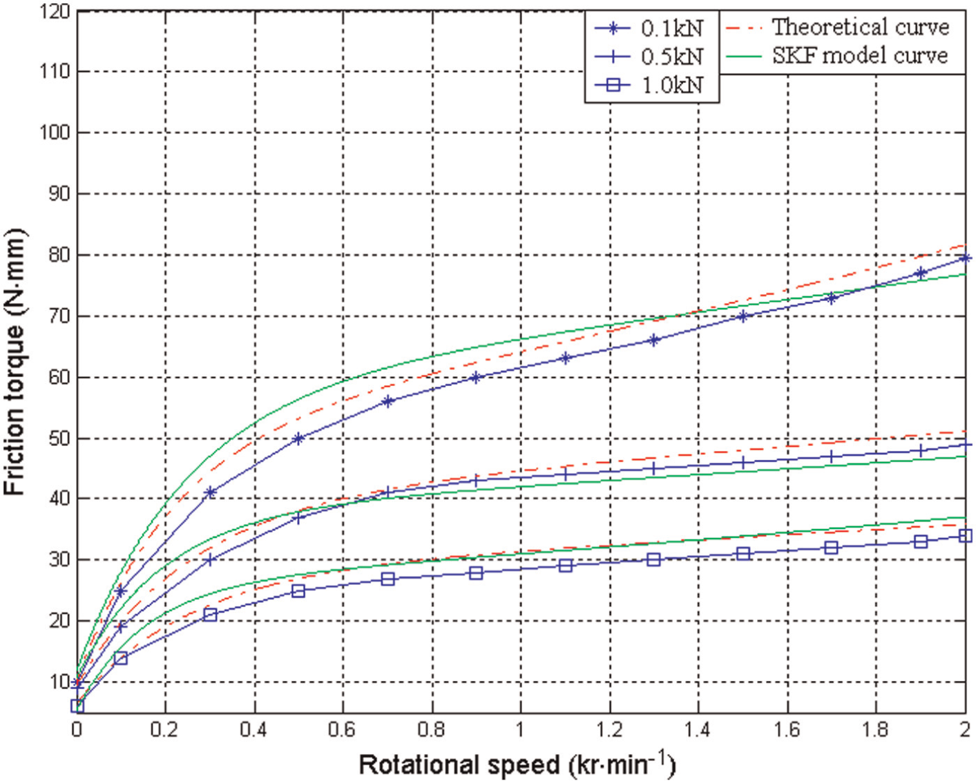
Figures 7 and 8 show the measured results, theoretical results, and SKF torque model results of frictional torques for the bearing with lubrication under different radial loads and rotational speeds, respectively. Figures 9 and 10 show the measured results, theoretical results, and SKF torque model results of frictional torques for the bearing without lubrication under different radial loads and rotational speeds.

Frictional torques of the bearing with lubrication under different radial loads.

Frictional torques of the bearing with lubrication under different rotational speeds.

Frictional torques of the bearing without lubrication under different radial loads.
Frictional torques of the bearing without lubrication under different rotational speeds.
It can be seen from Figures 7 and 9 that bearing frictional torque increases with the rotational speed increase under a given radial load. Especially, in Figure 7, the frictional torque under 0.9 kr/min are always the biggest one, which corresponds to the experimental results in Figure 8. As shown in Figure 8, due to the existence of dry friction, the frictional torque of the bearing with lubrication increases with the rotational speed increasing in the low-speed ranges (0–900 r/min). However, the bearing frictional torque starts to decrease due to the occurrence of lubrication film in the speed ranges of 900–1500 r/min. With the rotational speed increases, the viscous shearing force of the film increases. Therefore, bearing frictional torque increases again. However, as shown in Figure 10, the frictional torque of bearing without lubrication does not possess the characteristic of the bearing with lubrication. It is easy to understand that MC and ML due to the lubrication grease will not be considered in the bearing friction. Moreover, as shown in Figure 10, bearing frictional torque increases non-linearly with the rotational speed increasing. It can be seen from Figures 7 to 10 that the theoretical curves have a good agreement with the SKF torque model curves. However, both the results of them have an obvious deviation to calculate the frictional torque of the bearing with lubrication. Moreover, the theoretical model will be of a better accuracy than the SKF torque model in the high-speed ranges and bigger radial loads.
Conclusion
A theoretical analysis for the frictional torque components of deep-groove ball bearings was performed in this article. Especially, the stress and the strain analysis for the bearing subjected to radial loads was analyzed in detail. Ultimately, a special theoretical model for deep-groove ball bearings was presented. A frictional torque test apparatus was developed and the experiments for the bearing with lubrication and the other one without lubrication under different radial loads and rotational speeds were carried out. Comparisons of the theoretical results with the measured results and SKF torque model results were performed. Several conclusions are drawn through the theoretical analysis and experiments:
The frictional torque of deep-groove ball bearings mainly includes six components which are the frictional torques caused by elastic hysteresis of material, EHL, differential slip, spinning friction, friction between the balls and cage, and friction between the cage and guiding lands.
When the bearing bears a light radial load, the bearing frictional torque increases as rotational speed increases in the low-speed range (0–900 r/min). However, the bearing frictional torque decreases as rotational speed increases in the speed range (900–1500 r/min). When rotational speed exceeds 1500 r/min, the frictional torque increases with the speed increasing again.
The frictional torque of bearing with lubrication is larger than the bearing without lubrication in the low-speed ranges. However, as the rotational speed increases, the difference between them decreases.
As the radial load increases, the rolling frictional torque component caused by the elastic hysteresis will play a leading role in the total bearing frictional torque.
Footnotes
Acknowledgements
The authors would like to thank the students (Wenming Yuan and Leping Chen) for their contribution in the design and fabrication of the test rig.
Academic Editor: Yunn-Lin Hwang
Declaration of conflicting interests
The authors declare that there is no conflict of interest.
Funding
The authors would like to thank the National Science Foundation for Young Scientists of China for the financial support (Grant No. 51404276) in this research.