
Abstract
To improve gear-shifting quality of the clutch in automated manual transmission systems, motion trajectory tracking control of an electro-pneumatic clutch actuator is first considered in this article. Each chamber of the clutch actuating pneumatic cylinder is controlled independently by a pair of two-way on/off solenoid valves using pulse width modulation. Thus, motion and stiffness control of the actuating pneumatic cylinder can be realized simultaneously. With stiffness-maximizing control, the actuator has the best disturbance rejection from force to motion, which facilitates the realization of high-accuracy servo motion control. Nevertheless, model-based nonlinear control technologies are sure to require full-state information of the system. For cost considerations, nonlinear pressure observers which are independent of the load and stable in the sense of Lyapunov theory were applied to acquire the pressure states of the chambers in place of pressure sensors in this article. Moreover, a dedicated sliding mode controller with nonlinear pressure observers was put forward. Extensive experiments show that the proposed technical methods can fulfill the high-accuracy motion servo control of an electro-pneumatic clutch actuator.
Introduction
Automated manual transmission (AMT) systems, which can be easily added to existing manual transmission (MT) systems and occupy a large market share, not only possess the comfort and operation safety of automated transmission (AT) systems, but also have the fuel efficiency of MT systems. 1 In large-scale commercial vehicles and trucks, pneumatics is available for the existence of compressed air. Thus, an electro-pneumatic clutch actuator is utilized to automate the clutch actuation. To improve shifting quality and driving comfort, motion trajectory tracking control techniques are the key for tracking an optimal clutch trajectory during the clutch engagement process. High-accuracy servo control depends on model-based nonlinear control technologies, in which full-state knowledge of the system is necessary. However, in the whole electro-pneumatic clutch actuator system, only one displacement transducer is utilized to acquire position information of the clutch actuating cylinder. Moreover, pressure information of both chambers can be obtained by adopting the previously proposed nonlinear pressure observers taking the place of pressure sensors. 2
In recent years, a few researchers have devoted significant effort to address the position control of electro-pneumatic clutch actuators. Aschemann et al. 3 developed a nonlinear reduced-order observer to estimate the internal pressures in the electro-pneumatic clutch actuating cylinder and proposed a control structure consisting of a combined gain-scheduled feedforward and feedback control law by extended linearization techniques. Grancharova and Johansen 4 presented an explicit nonlinear model predictive controller to achieve reference-tracking control of an electro-pneumatic clutch actuator for heavy duty trucks. Langjord and Johansen 5 designed a dual-mode stabilizing switched controller for an electro-pneumatic clutch actuator, which is a combination of two controllers6,7 respectively based on backstepping technology and Lyapunov theory. Kaasa and Takahashi 8 implemented an adaptive robust tracking control algorithm based on a parallel feedforward compensator with a proportional valve for an electro-pneumatic clutch actuator. Qian et al. 2 proposed a compound sliding mode controller with globally stable pressure observers taking the place of pressure sensors to achieve servo control of an electro-pneumatic clutch actuator controlled by solenoid on–off valves. As we all know, the disturbance rejection of an actuator with a low stiffness is weak, and it will be worse for an actuator with a negative stiffness. The clutch load force is nonlinear, variable-stiffness and subject to hysteresis. And, there even exists negative stiffness at some stage. So, high-accuracy servo control of the electro-pneumatic clutch actuator is rather difficult, just through purely position control. Since compressed air is the working medium to transmit power in pneumatics, output stiffness of the actuating pneumatic cylinder could be promoted to improve the stiffness of the whole actuator system. Thus, the electro-pneumatic clutch actuator has better disturbance rejection from force to motion. The related studies are mainly about the control of actuator output force and stiffness. Shen and Goldfarb 9 adopted a pair of three-way valves to govern the pneumatic cylinder output stiffness independently of the pneumatic cylinder output force. Meng et al. 10 proposed an adaptive robust output force tracking control of pneumatic cylinder while maximizing or minimizing its stiffness.
In this article, a pneumatic cylinder governed by four on–off solenoid valves is considered as the clutch actuator of AMT systems, which is depicted in Figure 1. Simultaneous control of motion and maximized stiffness for an electro-pneumatic clutch actuator based on nonlinear pressure observers is presented to achieve high-accuracy servo control during the clutch engagement process. The rest of this article is organized as follows. The second section gives the dynamic models. In the third section, the simultaneous controller of motion and maximized stiffness designed specifically for the electro-pneumatic clutch actuator of AMT systems is presented. The experimental setup and results are discussed in the fourth section, and conclusions are drawn in the final section.

Schematic diagram of experimental setup.
Dynamic models
The pneumatic system shown in Figure 1 consists of a cylinder (FESTO AND-100-50-A-P-A-S11) controlled by four on–off solenoid valves (FESTO MHE3-MS1H-3/2G-1/8-K, configured as a two-way valve). The friction model was discussed and a simplified smooth model11,12 was proposed to represent the actual friction model in the subsequent study. So, the piston motion equation can be described by

where M is the inertia mass of moving parts; x is the piston position; pa is the absolute pressure of chamber A; pb is the absolute pressure of chamber B; p0 is the absolute ambient pressure; Aa and Ab are the effective piston areas of chamber A and chamber B, respectively; Ar is the cross-sectional area of the piston rod; bv is the viscous coefficient; Fl is the clutch load force as shown in Figure 2, which can be updated periodically by performing the non-model based sliding mode control algorithm;
13
and

Clutch load force.
Flow-rate characteristic of on/off solenoid valve is represented by the standard ISO 6358 based on the model of converging nozzle. The governing equation of the mass flow through the on/off valve port can be expressed as

where
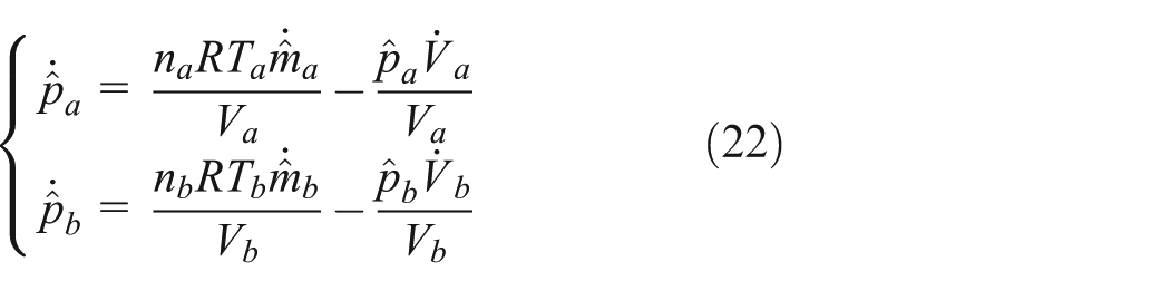
The differential equations that describe the pressure build-up in both chambers are given by

where na and nb are the polytropic indexes ranging from 1.0 to 1.4 for chamber A and chamber B, respectively; R is the gas constant; Va and Vb are the volumes of chamber A and chamber B, respectively; Ta and Tb are both approximated as the ambient temperature; and
According to equations (1)–(3), the entire system dynamics of the whole system from control input to motion output can be written as

where

where
Output stiffness of pneumatic cylinder is defined by

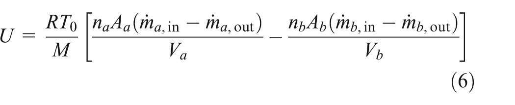
Thus, the dynamics from mass flow input to the output stiffness as a function of measured states can be written as

where V0a and V0b are the dead volumes of cylinder at beginning and end of stroke, respectively.
Controller design
In this section, a simultaneous controller of motion and maximized stiffness designed specifically for the electro-pneumatic clutch actuator of AMT systems is developed by incorporating the linear optimization method into the integral sliding mode control algorithm. The overall control structure is shown in Figure 3. The dedicated controller is required to track the reference engagement trajectory of clutch as closely as possible in the engaging process of clutch and to separate the clutch at the fastest rate during the disengaging process of clutch.

Block diagram of the overall control structure.
In the engaging stage of clutch, the control objective of the controller is to track the desired trajectory xd with guaranteed transient and tracking accuracy. Thus, an integral sliding surface which contributes to the performance improvement in steady state is selected as

where λ is a control gain; e = x − xd is the trajectory tracking error. Applying sliding mode approach and solving for the input for the case

Adding a robustness component, the robust control law is obtained

where Φ > 0 is the boundary layer thickness, sat(·) is the saturation function defined as

Kr is the robustness gain which can be expressed as
Simultaneous stiffness-maximizing control of the actuator will be introduced into the trajectory tracking control of the actuator for the purpose of better disturbance rejection from force to motion. On the basis of the combination of the linear optimization and sliding mode control approach, a dedicated motion controller for the electro-pneumatic clutch actuator can be developed with the possible maximum output stiffness of the system.
As described by the output-stiffness dynamics equation (8), the first-order derivative of the output stiffness is mainly determined by the net mass flow rates of both chambers of pneumatic cylinder. Defining a function as

where
According to the mass flow governing equation (3), the upper limit

where i = a, b indicate chamber A and chamber B of the cylinder, respectively.
According to equations (6) and (11), the equation representing the solid line shown in Figure 4 can be written as

where

Graphic method to solve the linear optimization problem.
As the objective function and constraints are all linear, a linear optimization approach can be applied to solve this two-variable problem. Therefore, the net mass flow rates of both chambers are given by
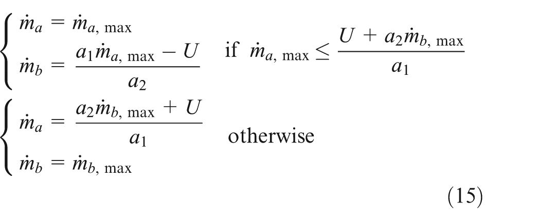

where i = a, b indicate chamber A and chamber B of the cylinder, respectively.
In the disengaging stage of clutch, the control objective of the controller is to separate the clutch immediately, while the accuracy is less important. First of all, a switching scheme with three operation modes for the electro-pneumatic clutch actuator is selected as follows: 13
Mode 1: chamber A fills, chamber B exhausts.
Mode 2: chamber A exhausts, chamber B fills.
Mode 3: both chambers are closed.
Thus, the system dynamics equation (4) can be rewritten as

where f(
A second-order sliding surface 14 is defined by

where ζ and ω are both constants.
Define the Lyapunov-like function

The control law u selected as u = −sign(s1) must guarantee the system to reach the sliding surface
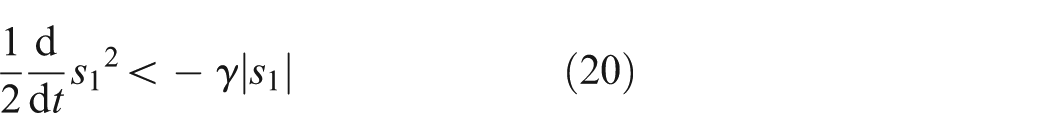
where γ is some positive constant, which determines the attenuation rate of the tracking error.
To reduce unnecessary valve chatter, a positive “dead zone”ε around zero is defined. Therefore, in the disengaging stage of clutch, the control law is expressed by

According to Qian et al., 2 a pair of globally stable closed-loop nonlinear pressure observers are adopted to acquire the pressure states of the chambers in place of pressure sensors, which can be described by
where
Experimental results
Experiments were performed on the electro-pneumatic clutch actuating system as shown in Figure 1 to demonstrate the proposed dedicated clutch controller. Figure 5 shows the picture of the experimental setup. A pneumatic cylinder (FESTO AND-100-50-A-P-A-S11) is controlled by on/off solenoid valves (FESTO MHE3-MS1H-3/2G-1/8-K, configured as two-way valve). Position information of the cylinder movement is measured by the resistance type linear position sensor (NOVOTECHNIK LWH75). The analog signals are acquired by a data acquire card (NI PCI-6251). A circuit board with four-channel pulse width modulation (PWM) drive circuit is developed for the synchronous updates of four duty cycles. The control algorithms with the program of C language in the Visual C++ environment are realized by computer and the sampling period is 2 ms. In our experiments, the observed pressures are used in the control algorithm, and the measured pressures are utilized only for comparison with the observed values in the result analysis.

Photo of experimental setup.
The system physical parameters are Aa = 7.854 ×10⁻³ m2, Ab = 7.54 × 10⁻³ m2, V0a = 6.214 ×10⁻⁵ m3, V0b = 2.916 × 10⁻⁵ m3, M = 2 kg, bv = 5000 N/(m s−1), Af = 50 N, C = 8.373 × 10⁻⁹ m3/(s Pa), b = 0.18561, L = 0.05 m, R = 287 N m/(kg K), Ts = 293.15 K, ps =6 × 10⁵ Pa, p0 = 1 × 10⁵ Pa. In addition, the controller and observer parameters for the experimental implementation are as follows: λ = 30, α = 0.1, η = 22000, Φ = 10, ζ = 0.1, ω = 500, γ = 22000, ε = 0.0004, na = 1.1, nb = 1.2.
The controller is first tested for tracking sinusoidal trajectories with different frequencies. Figure 6 shows the tracking results for the system executing a sinusoidal trajectory motion x(t) = 17.5 sin(πt − 0.5π) + 17.5 mm using the dedicated controller with nonlinear pressure observers. It can be seen that the reference trajectory cannot be tracked due to the output saturation of the controller during the first half of the cycle. Therefore, an extra experiment tracking a sinusoidal trajectory with a frequency of 0.4 Hz and amplitude of 17.5 mm was conducted. The related tracking results are shown in Figure 7. On comparing the observed pressures with the measured pressures of both chambers, we can find that the observed values are almost coincident with the measured values. As can be seen from Figure 7(a) and (b), although there are some considerable errors at the beginning, the steady-state motion tracking peak error is 0.44 mm. These may be caused by friction and by a very low stiffness in the initial stage. To confirm these suspicions, a set of experiment for tracking the similar sinusoidal trajectory with a frequency of 0.25 Hz shown in Figure 8 was performed under the condition that the initial states of both chambers should be pressurized. We can see that the maximum absolute value of the steady-state tracking error is 0.38 mm and the tracking errors at the beginning are significantly reduced. It is noted that in comparison with the pressures in the previous work,2,13 the pressures of both chambers in this article are maintained at a higher level which is close to the value of the supplied pressure. So, it is sure that the output stiffness of the electro-pneumatic clutch actuator is controlled to maximize at a maximum rate successfully.

Experiment results for tracking a 0.5 Hz sinusoidal trajectory: (a) reference trajectory (dashed curve) and tracking curve (solid curve), (b) control law of non-rod chamber, and (c) control law of rod chamber.

Experiment results for tracking a 0.4 Hz sinusoidal trajectory: (a) reference trajectory (dashed curve) and tracking curve (solid curve), (b) tracking error, (c) measured pressure (solid curve) and observed pressure (dashed curve) of non-rod chamber, and (d) measured pressure (solid curve) and observed pressure (dashed curve) of rod chamber.
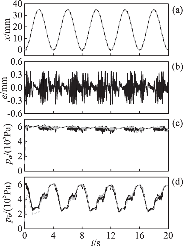
Experiment results for tracking a 0.25 Hz sinusoidal trajectory: (a) reference trajectory (dashed curve) and tracking curve (solid curve), (b) tracking error, (c) measured pressure (solid curve) and observed pressure (dashed curve) of non-rod chamber, and (d) measured pressure (solid curve) and observed pressure (dashed curve) of rod chamber.
To further test the tracking performance of the proposed dedicated controller, a smooth square trajectory as depicted in Figure 9 is considered and the maximal absolute tracking error is about 0.39 mm. The pressures of both chambers and the output stiffness are shown in Figure 9(c)–(e), respectively. Also, the pressures are higher than ever for the same smooth square trajectory. As we all know, the higher pressures in both chambers make the output stiffness bigger. Moreover, the observed pressures of both chambers are very close to the measured pressures. It means that the applied nonlinear globally stable and load-independent pressure observer can achieve the accurately acquirement of pressure information quite successfully in the motion trajectory tracking control of the electro-pneumatic clutch actuator. Therefore, an assumed optimal reference trajectory representing the whole operation process of the clutch was tracked. As the reference dashed curve in Figure 10, the clutch actuator system first disengages the clutch quickly toward the desired complete separation point x = 25 mm, then engages the clutch smoothly at a relatively slow rate after shifting into the desired gear, and finally engages the clutch quickly toward the position x = 0 mm when the rotational speed difference between the driving part and the driven part of clutch becomes close to 0. As can be seen from Figure 10, comparing the first period with others, the rise time of the first period is shorter than that of the subsequent periods. It is because that there exists a mass of compressed air in the chambers before the next cycle of the experiment. Therefore, one proposal that the compressed air in both chambers should be exhausted before each separation of the clutch is presented. As shown in Figure 10(b) and (c), the phenomenon that the pressures of both chambers rise rapidly and then be maintained near the supplied pressure indicates that simultaneous stiffness-maximizing control is implemented successfully. Moreover, the observed pressures are basically in coincidence with the measured pressures, which demonstrates the effectiveness of the applied nonlinear pressure observers in implementing the servo control of clutch. Figure 11 shows the enlarged figure of the first period of Figure 10(a). The related tracking result shows that the dedicated controller with the nonlinear pressure observers can separate the clutch rapidly with a tiny overshoot and engage the clutch smoothly with the maximum trajectory tracking error of 0.38 mm.

Experiment results for tracking a 0.25 Hz smooth square trajectory: (a) reference trajectory (dashed curve) and tracking curve (solid curve), (b) tracking error, (c) measured pressure (solid curve) and observed pressure (dashed curve) of non-rod chamber, (d) measured pressure (solid curve) and observed pressure (dashed curve) of rod chamber, and (e) observed output stiffness.

Experiment results for tracking an assumed optimal reference trajectory periodically: (a) reference trajectory (dashed curve) and tracking curve (solid curve), (b) measured pressure (solid curve) and observed pressure (dashed curve) of non-rod chamber, (c) measured pressure (solid curve) and observed pressure (dashed curve) of rod chamber, and (d) observed output stiffness.

Tracking results of the first period for tracking an assumed optimal reference trajectory: (a) reference trajectory (dashed curve) and tracking curve (solid curve) and (b) tracking error.
Conclusion and future work
The high-accuracy servo control of an electro-pneumatic clutch actuator driven by four two-way valves has been investigated in this article. A dedicated controller consisting of two parts, an engagement part and a disengagement part, is proposed for the operations of clutch. Output stiffness-maximizing control of the actuating pneumatic cylinder is introduced to weaken the effect of negative or low stiffness of the clutch load characteristics. Therefore, simultaneous motion and stiffness-maximizing control designed specifically for the engagement process of the electro-pneumatic clutch actuator of AMT systems are developed by incorporating the linear optimization method into the integral sliding mode control algorithm. For cost containment, nonlinear globally stable and load-independent pressure observers proposed in previous work are applied to observe pressures in both chambers taking the place of pressure sensors. Non-model-based sliding mode control is adopted to separate the clutch at the fastest rate during the disengaging process of clutch. Extensive experimental results illustrate the effectiveness of the proposed dedicated controller for the electro-pneumatic clutch actuator of AMT systems.
As there exist a large extent of parametric uncertainties and rather severe uncertain nonlinearities in the modeling of the electro-pneumatic clutch actuator system, such as the time-varying friction force, the simplified flow rate characteristics of the valve port, and unknown disturbances, an adaptive robust control strategy 15 should be employed for the electro-pneumatic clutch actuator to achieve a higher-accuracy servo control for the electro-pneumatic clutch actuator in future work.
Footnotes
Academic Editor: Mario L Ferrari
Declaration of conflicting interests
The author(s) declared no potential conflicts of interest with respect to the research, authorship, and/or publication of this article.
Funding
The author(s) disclosed receipt of the following financial support for the research, authorship, and/or publication of this article: This work is supported by the National Natural Science Foundation of China (grant no. 51605194), the China Postdoctoral Science Foundation (grant no. 2016M591921), the Natural Science Foundation of Jiangsu Province of China (grant no. BK20160531), and the Natural Science Foundation of Jiangsu University (grant no. 15JDG152).