
Abstract
This study proposes a gain-scheduled controller with direct tuning for the position control of a pneumatic clutch actuator that is installed in heavy-duty trucks. Pneumatic clutch actuators are highly nonlinear systems and cannot be easily controlled. Industries require a simple controller design that is easy to understand and requires few trial-and-error calibrations. Therefore, we adopted a gain-scheduled proportional integral derivative (PID) control law, which is a well-known and easy-to-understand nonlinear control method. In this approach, a gain scheduler is expressed using polynomials composed of coefficient parameters and controlled object states. The unknown coefficient parameters of the polynomials are directly tuned from the controlled object input/output data without having to use a controlled object model. The proposed controller design procedure is simple and does not require system identification or trial-and-error tuning. The effectiveness of the proposed method is verified by an experiment using an actual vehicle. The experimental results confirm the effectiveness of the proposed method for the position control of pneumatic clutch actuators.
Keywords
Introduction
The demand for driving comfort is increasing, with the automotive industry moving toward automatic transmissions not only for passenger vehicles but also for heavy-duty trucks. Automatic transmission (AT) and continuously variable transmission (CVT) are used in passenger cars but are unsuitable for heavy-duty trucks because of their high cost and low efficiency. 1 Automated manual transmission (AMT), which is manual transmission (MT) with electronic-controlled clutch and gear actuators, has advantages such as low cost, high efficiency, and improved fuel efficiency, and is used in large trucks. An automatic control of the clutch connection plays an important role in AMT vehicles. 2 In general, a hydraulic system is preferred for position control,3,4 whereas pneumatic clutch actuators are used in heavy trucks given that compressed air comes preinstalled in such vehicles. In addition, ON/OFF valves are used owing to their cost-effectiveness, compactness, and robustness. In a pneumatic clutch system, it is difficult to perform the desired and sensitive position control because of the compressibility of air, the nonlinearity in the clutch spring reaction force, and the use of ON/OFF valves.
The automobile industry uses control laws based on feedforward and proportional integral derivative (PID) control, which have low computational cost and are intuitive. 5 PID control is used in more than 90% of the closed-loop. 6 The control law often consists of a look-up table (LUT) tuned by trial and error7,8 because many automobile devices have nonlinearity. On the other hand, with the rapid adoption of electronic control in recent years, the time required for parameter tuning has increased. 9 To this end, model-free control and data-driven control have been explored10–22 and applied to automobile systems.5,23–26
Thus far, the control of pneumatic clutch actuators has been accomplished through use of model-based approaches, including H∞ control, 27 sliding mode control,28,29 model predictive control,30–33 adaptive control, 34 state feedback control using feedback linearization, 35 fuzzy control, 36 and backstepping control. 37 In these methods, an observer is required to construct a state feedback controller; an observer for estimating the pressure inside a clutch piston has been proposed.38,39 Some previous studies reported satisfactory control performance; however, system identification was required for model-based control. As a pneumatic clutch actuator is a nonlinear system, 1 a considerable amount of time is required to establish an accurate mathematical model. Identifying an accurate mathematical model remains a significant challenge. Additionally, neural networks have been investigated for PID control. 40 However, the calculation cost associated with neural networks is an issue.
Herein, we propose a practical position control method that requires less calibration time for the tuning process and calculation cost for a pneumatic clutch actuator with strong nonlinearity. This method features a gain-scheduled control law with a polynomial as the gain scheduler and enables direct tuning of the gain-scheduling parameters without use of a controlled model. Gain-scheduled control is an efficient and effective approach for actual nonlinear systems. 41 The design method can derive the Linear Matrix Inequality (LMI) using the Linear parameter-varying (LPV) model. Otherwise, the controller parameters need to be tuned at each operating point. In other words, tuning by trial and error or modeling of the nonlinear system is required. To deal with these issues, we construct a method for automatically tuning the control parameters directly from the input/output data of the controlled object without system identification. This is expected to improve the development efficiency. In addition, gain-scheduled control using an LUT (which is often used in the automobile industry) can express the nonlinearity but is not preferred for mass production because the required ROM area is considerable. Therefore, a gain scheduler (scheduling function) with a polynomial composed of the controlled object states and coefficient parameters is constructed. This helps reduce the ROM area and vary the control parameters based on the clutch position and speed. A previous study 31 attempted to eliminate the nonlinearity between the valve signal and the amount of air by creating a correlation map between the duty ratio of the valve and the amount of air. However, it is generally difficult to measure the absolute amount of flow rate. Therefore, in this study, the duty ratio of the PWM (Pulse Width Modulation) control provided to the solenoid valves (i.e. the control input) is calculated directly from the clutch state quantity (i.e. position and speed) without having to establish a correlation map between the valve duty ratio and the flow rate. The direct tuning method is based on virtual reference feedback tuning (VRFT), 11 which is a data-driven control method. Here, the coefficient parameters of the scheduling function and the basis function are linearly combined. This allows linear regression, which is a feature of VRFT, and the optimum solution of the coefficient parameters of the scheduler can be obtained using a linear regression algorithm such as the least-squares method. To the best of our knowledge, there have been no prior studies that applied a direct tuning method to gain-scheduled controllers for pneumatic clutch actuators.
The rest of this paper is organized as follows. Section 2 briefly describes the model of the pneumatic clutch actuator (i.e. the controlled object and the control law). Section 3 describes the automatic tuning method for the gain-scheduled control using the VRFT. In Section 4, the effectiveness of the proposed method is verified through actual vehicle tests. The obtained results confirm that the automatically tuned gain-scheduled control can achieve the desired position control. Section 5 presents the conclusions drawn from the study results.
Control system
Pneumatic clutch actuator system
Figure 1 shows the pneumatic clutch actuator system. The pneumatic clutch actuator system is the controlled object which is comprised of a valve system, a clutch actuator, and a clutch. The valve system has a supply side with two ON/OFF solenoid valves (valve 1 and valve 2). The exhaust side also has two ON/OFF solenoid valves (valve 3 and valve 4). The flow from the valve system enters chamber A and is converted to pressure. Under the pressure action on the piston, the piston moves, and a force acts on the spring, thereby generating a clutch torque. In other words, in a pneumatic clutch actuator, position control is performed to arrange the transmissible torque.

Layout of the electro-pneumatic clutch (EPC) system comprising three components. The valve system has two supply valves denoted by valves 1 and 2, and two exhaust valves denoted by valves 3 and 4. The clutch actuator has a chamber and piston, and a spring and a damper for initial set position. The clutch has a mass, a spring, and a damper.
The model of the system is shown in Figure 1. As no controlled object model is used in this study, the description of this system is simple. Note that the physical model shown in Figure 1 can essentially express both the clutch actuators of which clutch spring is directly actuated using the pressure bearing and indirectly actuated using a set of levers. The physical model of the clutch actuator can be expressed as follows:


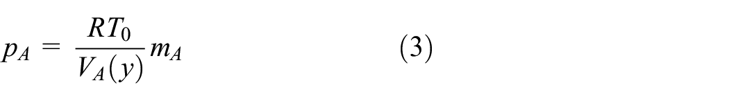


where y is the piston position, v is the velocity, p A is the pressure in the chamber A, w t (p A , d) is the flow rate for chamber A, and m A is the mass of air in chamber A. d is the vector of the operation signal d i (i = 1, 2, 3, 4) for each valve, and w vi (p A , d) (i = 1, 2, 3, 4) is the flow rate generated at each valve. A A is the area of chamber A. A0 is the area of chamber A minus the area of the piston rod, M is the mass of the piston, P0 is the atmospheric pressure, T0 is the temperature, and R is the gas constant of air. V A (y) is the volume for chamber A, and V A (y) = VA0 + A A y, where VA0 is the dead volume of chamber A (volume in chamber A under atmospheric pressure). f l (y) and f f (v) are the clutch spring reaction force and frictional force, respectively. The mass flow rate w vi of each valve formulated in ISO/DIS 6358 42 and in literature 43 is as follows:


where A vi is the orifice effective area, T h is the supply-side temperature, T0 is the standard temperature, p h is the pressure on the high side, p l is the pressure on the low side, and C i is determined by the valve characteristics. Figure 2 shows an example of the relationship between the clutch position y and the clutch load f l (y), wherein the curve characteristic is linear to a certain position but thereafter becomes nonlinear, including hysteresis. 44

Characteristics of the spring used in the electro-pneumatic clutch (EPC) system. 44 The relationship between clutch stroke y (mm) and the load fl (N) is hysteretic and static nonlinear.
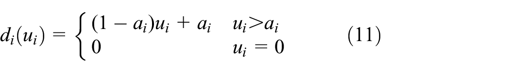
Next, the dead zone of the ON/OFF valve is described. In this study, the ON/OFF valve is driven by the PWM. In other words, the operation signal d i for each valve is the duty ratio. When the duty ratio is low, there is a dead band width, wherein the valve is nonoperational. The dead zone Da(d i ) with the dead zone width [0, a i ] is expressed as

Control law
From Section 2.1, we find that there are nonlinear elements such as the pneumatic cylinder, clutch spring characteristics, mass flow rate–valve input relationship, and ON/OFF valve. We construct a control law to deal with these nonlinearities. Figure 3 shows the control law comprising gain-scheduled control, saturation, valve selection, and dead zone compensation. Here, r is the target value, y is the clutch position, u is the control input calculated by the gain-scheduled controller, u s is the control input after saturation, u i (i = 1, 2, 3, 4) are the control input assigned to each valve that is the duty ratio, and d i (i = 1, 2, 3, 4) assigned to each valve are the duty ratio applied to the valve after dead zone compensation is performed.

Control law for electro-pneumatic clutch actuator. The system is composed of gain-scheduled control and saturation compensation, valve selection, and dead zone compensation for the valves.
The gain-scheduled control method achieves the desired control by changing the control parameters based on the environment and state of the controlled target. The gain-scheduled control is explained in detail in the next section. The saturation function S (u) is expressed as

where u is the control input, and s ub and s lb are the upper and lower limits of the control input, respectively. In other words, the range of the control inputs after saturation is S(u) ∈ [s ub , s lb ]. For a total of four valves, when the duty ratio given to each valve is u i ∈ [0, 1] (i = 1, 2, 3, 4), the control input becomes u ∈ [−2, 2]. In other words, s ub = 2, and s lb = −2. Next, the method of selecting the valve to be driven is explained using Table 1. The control input of u s ∈ [−2, 2] is distributed to each valve. In this study, the orifice diameter of each valve is the same. Hence, if the control input is u s ∈ [0, 1], only valve 1 on the supply side is used, and if u s ∈ [1, 2], both valves 1 and 2 on the supply side are used. The same applies to the exhaust valve side. For the dead zone compensator d i (u i ), the minimum lower limit value a i (i = 1, 2, 3, 4) of the duty ratio at which the clutch position starts to operate for each valve is added.
Actuated valve selection.

where u i is the duty ratio given to the valve before the dead zone compensation. To reduce valve operation as much as possible, the valves are switched off when the error in the clutch position with respect to the target value is within a predetermined threshold and remains in a predetermined duration.
Gain-scheduled control
We consider the application of the gain-scheduled PID controller to the position control of a pneumatic clutch actuator. First, the fixed PID control input is described as

with
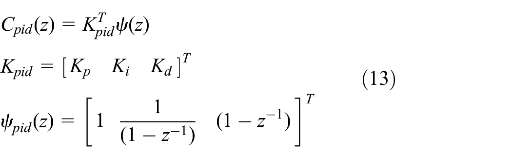
Figure 4 shows a feedback control system comprising a feedback controller and the pneumatic clutch actuator system derived in Section 2.1. From Figure 4 and equations (3) and (4), we see that the pneumatic clutch actuator includes an integral element between the control input and the mass of air. In other words, when the control input acts, the piston chamber pressure and clutch position vary. Considering the valve as a part of the controller, the integral term is already included in the controller. Therefore, the second term, which is the integral element of equation (13), is no longer necessary, and PD control is used as the digital controller. 45

Block diagram of the feedback system for the pneumatic clutch actuator. The system is composed of a digital controller and a pneumatic clutch actuator. The pneumatic clutch actuator system has an integral valve part. In this system, an integral term is not required for digital control.
Figure 5 shows a block diagram of the gain-scheduled control system. The gain-scheduling PD control is as follows:


Gain-scheduled control system. Controller gain is varied by gain scheduler based on the scheduling parameters, which are the states of the pneumatic clutch actuator system.
with

where f(x) is the scheduling function vector, Kj(x) is the PD gain scheduler (scheduling function), and x is the scheduling parameter vector. In this study, the gain scheduler in equation (15) uses a polynomial. The just-in-time method, 46 database control, 14 and neural network 47 are difficult to implement in mass-produced controllers because of computational costs and ROM area limitations. Gain schedulers using LUTs have been used in industries, particularly for automobile control. However, the required ROM capacity is high, and the number of tuning parameters is considerable. Another concern in the gain-scheduled control with LUTs (which express the gain designed for each operating point) is the rapid fluctuation in the PD gain, which destabilizes the system. In this study, the scheduling function is represented by a quadratic polynomial, equation (16). As a result, the number of storage parameters is reduced, and the gain varies continuously. The latter makes it difficult for sudden gain changes to occur.

where x1 and x2 are the scheduling parameters, which are the clutch position and speed, respectively. x sf is the function vector (basis function) of the scheduling parameter, and wj is the respective weight coefficient (regression coefficient) vector for the PD gain.
Automatic tuning method for gain-scheduling parameters
Virtual reference feedback tuning 11
In VRFT (which is a data-driven control method), the control parameters are directly obtained from open-loop input/output data without system identification. The optimum control parameters are tuned such that the reference model and the closed-loop system have the same characteristics. Figure 6 shows the structure of the VRFT. C, M
d
, and P represent the controller, reference model, and controlled object, respectively. u(t) and y(t) are the input and output, respectively. ρ is the control parameter, z is the shift operator, and s is the Laplace operator.
Step 1: Let M d be the desired closed-loop reference model and the input/output data of a controlled object be u(t), y(t), t = 1…, N
Step 2: By considering y (t) as the output of the reference model, the virtual reference signal that generates y (t) is determined as

Step 3: We consider this signal as the closed-loop reference signal in Figure 1. At this time, the virtual-manipulated variable created by the controller is expressed as

Step 4: If the virtual-manipulated variable and the manipulated variable are similar, the closed loop with the controller is considered close to the reference model. In this case, the cost function to be minimized is given by the following equation.
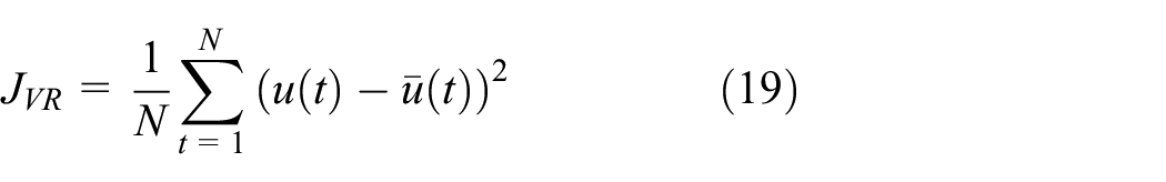
From equation (18), the above equation can be rewritten as follows:

with

Step 5: Introduction of prefilter L

Concept of VRFT, which uses a virtual reference signal made of user-defined reference model M d and controlled variable y. Controller parameter, ρ, is tuned without controlled object, P(s).
In equation (17), the reference model has an inverse matrix, which is nonproper. This issue is solved by adding a prefilter. Adding the prefilter L to equation (20) yields the following equation:

with


We explain the implications of VRFT based on literature.
12
Let C
d
be the controller that achieves the reference model. We suppose that

From this equation, if
Optimization of gain-scheduling parameters by VRFT
We derive a new cost function to obtain the optimum value of the weighting coefficient of the gain-scheduling function. From the cost function of VRFT (see equation (22)) and the equations (14) to (16) related to the gain-scheduling PD control, the cost function for the gain-scheduling PD control using VRFT (GS-PD-VRFT) is as follows.


with


where

with


Algorithm
The algorithm for the weighting coefficient (control parameter) in the automatic tuning of the gain-scheduling function using VRFT is shown below.
Step 1: Measure the input/output data of the controlled object.
Step2: Define the reference model.
Step 3: Determine the candidates of the scheduling parameters and design the scheduling functions for each PD gain.
Step4: Design the VRFT prefilter.
Step 5: Find the weighting coefficient (control parameter) of the scheduling function that minimizes the cost function.
In Step 1, the pneumatic clutch actuator includes an integral element between the control input and the clutch position (shown in Figure 1). The input/output data are acquired in a closed-loop manner in a system that includes this type of integral element. 25 In addition, the saturated input u s is used to derive the control parameters that consider input saturation. 19 The reference model of Step 2 is described. The clutch position and torque are correlated. For example, if an undershoot occurs during half-clutch control, the torque fluctuates rapidly, and a shift shock occurs. Therefore, a response without over/undershoot is desirable. The n-order transfer function, expressed in equation (33), is known as the reference model that does not induce overshoot because all the poles exhibit a negative real part. In addition, there is a dead time between the instruction provided to the valve and the operation of the clutch. The reference model can be expressed by the following equation:
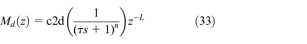
where τ is a time constant that represents the response speed, n is the order, L is the lag step, and c2d is the conversion from the s region to the z region. In Step 4, the original cost function and the cost function of the VRFT can be matched by applying a strict prefilter, as done in previous studies.16,21 However, the prefiltering requires multiple additional experiments. Herein, the prefilter described in equation (34) is used for practical use. 15

Experimental verification
Outline of the experiment
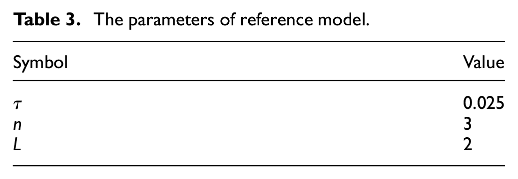
Figure 7 shows the outline of the system for experimental validation. The test vehicle is an actual heavy-duty truck (GVW class weighing approximately 25 t), and the installed diesel engine is a 6UZ1-TCS model (type: six-cylinder OHC direct-injection diesel, displacement: 9839 cc, compression ratio: 16.2, maximum power: 279 kW/1800 rpm, maximum torque: 1814 N · m/1000–1200 rpm). The pneumatic clutch actuator used in this experiment was designed for heavy-duty trucks, similar to the one described above. The supply pressure is 850 kPa, and the battery voltage is 24 V. Table 2 shows the dead zone of the valves. The controller used is a rapid prototyping control system consisting of MABX and RapidPro from dSPACE. The proposed method was programed in MATLAB®/Simulink® (ver. 2015a SP1) from MathWorks and implemented in MABX. The various signals were measured as time-series data sent from MABX to a notebook PC. The control law shown in Figure 3 is implemented on RCP, and the PC performs the direct tuning procedure in this paper. Note that, at the time of commercialization, performing all procedures on the controller is possible by measuring the input/output data and solving the least squares problem shown in equation (30) since the setting values for steps 2–4 of the proposed algorithm can be predetermined. The sampling period was 10 ms, and the PWM period was 20 ms. Table 3 shows the parameters of the reference model.

Experimental system. The test vehicle is an actual heavy-duty truck in which RPC and AMT, including CAS and gearbox are installed. RPC is used as the TCM. The signals are measured by communication between PC and RPC. The program is written in MATLAB/Simulink. The ECM and TCM communicate via CAN. Signals of the ECM operate the engine. The AMT including CAS and gearbox is operated using the RPC signals. RPC: rapid prototyping controller; ECM: engine control module; TCM: transmission control module; CAS: clutch actuator system; CAN: controller area network.
Dead zone of valves.

The parameters of reference model.
Experimental results and discussion
As shown in Algorithm Step 1, the input/output data of the controlled object are acquired by conducting a closed-loop experiment. The PD controller was used, and the fixed PD gains were set to K p = 0.5 and K d = 0.2. The input/output data were acquired by setting the same target values as the actual vehicle launch and shift waveforms. Figure 8 shows the time-series data when the closed-loop test was performed. The horizontal axis represents the time, while the vertical axis represents the clutch position, intake-side valve duty ratio, and exhaust-side valve duty ratio. When the clutch position is 0 mm, the clutch is fully engaged, and when it is 16 mm, the clutch is fully disengaged. When the clutch position is approximately 8 mm, it is in a half-clutch state. Figure 8(b) confirms that an undershoot occurred during the half-clutch control. This is undesirable because a sudden torque is generated due to the unintended clutch connection. The weight coefficient of the gain scheduler is calculated using the input/output data shown in Figure 8(a). Figure 9 shows the time-series data of the closed-loop system when the gain-scheduled control is applied. The target clutch position is the waveform calculated in the transmission control module. The horizontal axis represents the time, while the vertical axis represents the clutch position, valve duty ratio on the supply side, valve duty ratio on the exhaust side, proportional gain, and differential gain. Figure 9 shows that the response follows the target without any over/undershooting. The over/undershoot amounts prior and subsequent to direct tuning are 0.8/1.8 and 0.48/0.25 mm, respectively. This is the same characteristic as that of the defined reference model. Furthermore, it is considered that the response closer to the limit of the system can be achieved from the valve duty ratio. Regarding the proportional gain, the relationship between the clutch position and the load is nonlinear (see Figure 2). Hence, the proportional gain changes accordingly. The differential gain is lower than the proportional gain due to the fluctuation in the clutch position. This fluctuation is due to the eccentric movement of the clutch as the engine rotates. Examination of Figure 9 indicates that the characteristics are close to the provided reference response because there is no over/undershooting. Conversely, as the control input is saturated, the system gives a reference response that cannot be achieved. In other words, the model matching is not possible due to physical constraints. To further confirm the matching between the reference model and the closed-loop characteristics, the response when the control input is not saturated is confirmed. Figure 10 shows the time-series data when the reference response that can be achieved in the system is given. The horizontal axis represents the time, whereas the vertical axis represents the clutch position and the tracking error. In the clutch position stage, the reference response is shown in addition to the target value and the actual response. Examination of Figure 10 confirms that the actual response follows the set reference response. In other words, the closed-loop system could approach the characteristics of the set reference model. Based on the above, the proposed gain-scheduled control and automatic tuning method were used to directly design a gain scheduler without system identification. Its effectiveness was confirmed by conducting actual vehicle tests. In addition, since the control method is practical and cost-effective, it can be easily implemented in mass-produced controllers and is expected to facilitate development due to the automatic parameter tuning feature.

Closed-loop data with fixed PID gain. Proportional gain is 0.5, derivative gain is 0.2: (a) overview of time series and (b) enlarged view of time series. Responses exhibit over/undershoot, causing shift shock because of sudden torque changes. The clutch position, 0 mm: fully engaged, the clutch position, 16 mm: fully disengaged, the clutch position, approximately 8 mm: half-clutch state.
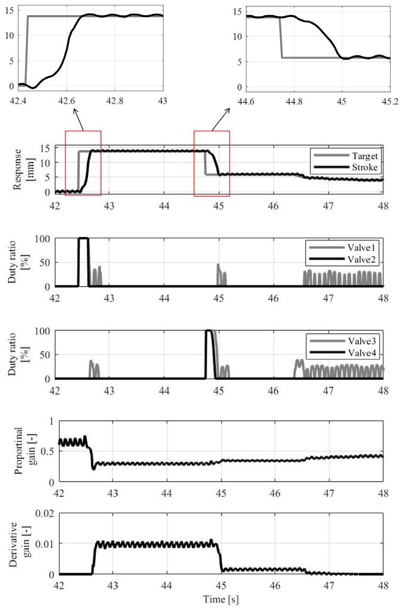
Closed-loop data with gain-scheduled PID control. The closed-loop system is close to the reference model because the response shows no over/undershoot. Proportional gain and derivative gain are varied depending on the state of the clutch actuator system.
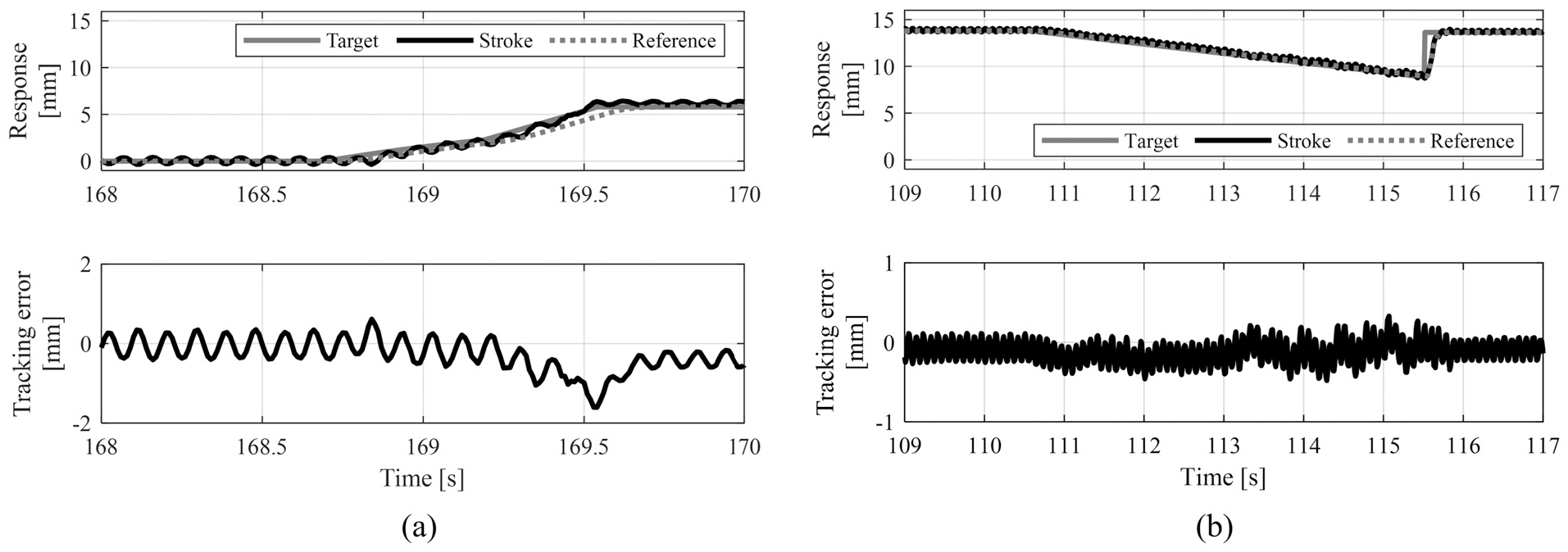
Closed-loop data with gain-scheduled PID control under no saturation of the valves: (a) target of the clutch stroke moves from the engaged side to near the kiss point and (b) target of the clutch stroke moves from disengaged side to near the kiss point and finally back to the disengaged side. These figures confirm the matching between the response and reference signals.
Conclusion
In this paper, we proposed a control law and a direct tuning method for gain-scheduling control parameters for the position control of a pneumatic clutch actuator which does not require a controlled object model. First, the pneumatic clutch actuator system was found to have strong nonlinearity in terms of the ON/OFF valve, pneumatic parameters, and spring characteristics. Next, we derived a control law comprised of gain-scheduled control and valve dead zone compensation. In the gain-scheduled control, the gain scheduler was represented by a polynomial, and the number of tuning parameters was reduced compared to that in the gain scheduler with the LUT. The LUT is often used in industries. Furthermore, we derived an automatic tuning method for these parameters and showed that the parameters can be obtained through use of optimization algorithms, such as the least-squares method. We experimentally confirmed the effects of the control law and direct tuning method. As a result, the controller parameters could be obtained directly from the input/output data of the controlled object. The PD gain was adapted based on the controlled object states, and good results were obtained for the target value. Thus, it was possible to achieve control with a small computational load and less calibration time required by the industry for pneumatic clutch actuators with nonlinearity. Future work will include the construction of reference response design methods that evaluate the saturation of the control inputs and online tuning methods.
Footnotes
Handling Editor: James Baldwin
Declaration of conflicting interests
The author(s) declared no potential conflicts of interest with respect to the research, authorship, and/or publication of this article.
Funding
The author(s) received no financial support for the research, authorship, and/or publication of this article.