
Abstract
The precise control of corresponding clutch pressures is essential to the gearshift quality of vehicle transmissions. The electro-hydraulic clutch-actuator system is widely utilized by vehicle transmissions because of the character of fast response and accurate pressure regulating capability. However, due to the structure of vehicle transmissions, pressure sensors are hard to be mounted to measure the clutch pressure during the shifting process directly. An observer method basing on the reduced order dynamic model of the hydraulic clutch actuator system and the Unscented Kalman Filter (UKF) method is proposed in this paper to ensure a stable and precise control of the clutch actuator system. The reduced order non-linear dynamic model of the clutch actuator system is established basing on the flow distribution character and coupling motion of the valve spool in the system. A state observer is proposed to estimate the clutch pressure online using the output pressure signal of the pressure control valve based on the UKF method. Simulations and experiments are carried out to verify the proposed clutch pressure observe method. The results reveal that the reduced order dynamic model can predict the pressure dynamics inside the hydraulic system accurately and the observer can ensure the estimate accuracy of clutch pressure during the shifting process.
Keywords
Introduction
Automatic transmission (AT) is widely utilized in various kinds of vehicles because of the continuous power shifting and self-adjustment capability. 1 The ever-increasing regulatory requirement on CO2 emissions drives the efficiency improvement of vehicle powertrain systems, which leads to more gear steps of AT to offer a broader ratio spread, finer ratio steps and enable the engine to operate at its efficient regions more often.2,3 The increasing number of gear steps leads to the birth of new transmission topology structure and entire new shifting method. A gear shift in AT with the commonly used transmission topology structure need to disengage one off-going clutch and engage one on-coming clutch in a proper manner, which is termed clutch to clutch shift or single transition shift (STS). Some research have stated that double transition shift (DTS), which need two pairs of clutches to be engaged and disengaged during a gear shift, enables multiple-speed AT with minimum number of planetary gear sets and clutches. 4 With the development of electro hydraulic actuators, topology structures with DTS gear shift technology have been adopted by increasing transmission manufactures.5–8 Moreover, new shifting strategy, for example, which allows the kick down from eighth gear to third gear (indirect shift), are often introduced in multiple gear transmissions in order to improve the driving performance. Double transition gear shift is usually adopted in such shift conditions. 9
The increasing number of clutches employed in the gear shift makes the shifting process more complex and harder to achieve a satisfying shift quality. Therefore, the shift quality control technology for DTS is demanded by the development of multiple speed automatic transmission.
Hussein adopted lever analog to understand the dynamics of an automatic transmission during a DTS. 5 Di developed a dynamic model of a patented GM double transition transmission gearbox basing on multi-body dynamics theory and studied the effect of the initial step and pressure slop of clutches on the shift quality.10–12 Mirko proposed a pseudo spectral collocation method to optimize the control trajectories during the DTS of a 10-speed to reduce the jerk and clutch energy loss. However, the optimized clutch pressure trajectories were still calibrated by open-loop control, which is time consuming and not robust to uncertainties of the hydraulic system. 13
The precise control of corresponding electro-hydraulic actuator system is essential to the shift quality of automatic transmission. The system is composed of a solenoid valve, a pilot operated pressure control valve and a clutch piston in majority of high power automatic transmission for its large flowrate and excellent pressure regulating capacity. 14 However, due to the structure of automatic transmission, pressure sensors are hard to be mounted to measure the clutch pressure directly during the working process. Variety of pressure observe methods have been proposed to estimate the clutch pressure during single transition shift (STS).
Several observe methods basing on vehicle speed signals have been proposed to estimate the clutch pressure and transmitted torque of transmissions. Sarawoot proposed a model-based open loop adaptive sliding mode observer for the simultaneous estimation of clutch pressure and transmission input torque for an automatic transmission.15,16 Jin-Oh presented an observer-based algorithm to estimate the output pressure of a hydraulic actuator in a vehicle power transmission control system basing on the clutch slip velocity and the model of the hydraulic actuator subsystem. 17 Gao etc. proposed a reduced order clutch pressure observer in the concept of input-to-state stability (ISS). Model uncertainties including steady state errors and unmodeled dynamics in the driveline system are considered as additive disturbance inputs and the observer is designed so that the error dynamics is input-to-state stable.18–22
However, these methods may cause large error during the filling phase and torque phase of a gear shift. Moreover, these methods are hard to be utilized to estimate the clutch pressure of double transition shift, during which more than one pair of clutches need to be controlled simultaneously. Virinchi proposed a MEMS technology based sensor to measure the clutch pressure directly, but the method is not cost effective yet. 23 New estimation method which is suitable for the application of both STS and DTS is needed by the development of multi-speed gearbox.
The Kalman Filter is a powerful tool for estimating and predicting system states in the presence of uncertainty in linear systems. It is extended by using linearization procedures, such as Extended Kalman Filter (EKF)24,25 and Unscented Kalman Filter (UKF)26,27 to solve the estimation of nonlinear dynamic systems. Compared to EKF, the UKF is more effective in the estimation of highly nonlinear systems with non-Gaussian uncertainties and causes less estimation error. 28 UKF has been used in state estimation of vehicle dynamics in several researches. Ma etc. presented a computational method based on UKF algorithm to estimate the longitudinal and lateral velocities of heavy trucks on a sloping road. 29 Zhao etc. build a model of a DCT vehicle powertrain system and estimate the torque transmitted by a twin clutch during the up shifting process based on UKF. 30
In this study, the working principle and modeling of the hydraulic clutch actuator system are introduced in Section “Working principle and modeling of the hydraulic clutch actuator system.” A reduced order model of the hydraulic clutch actuator system is proposed in Section “Model reduction of the hydraulic system” basing on the proposed nonlinear model and the activity index of each element in the system. An UKF observer is proposed in Section “State observer design” to estimate the clutch pressure using the output pressure signal of the pressure control valve, which is usually measured by the pressure sensors on the valve for Fault diagnosis. Simulations are conducted to examine the effectiveness of the proposed estimation method. In Section “Experimental analysis,” experimental study is proposed to verify the dynamic model of the system and the proposed observe method. The conclusions of this study are presented in Section “Conclusion.”
Working principle and modeling of the hydraulic clutch actuator system
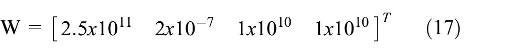
The schematic of a typical hydraulic system of automatic transmission is shown in Figure 1. The system is commonly constituted by the oil supply system and several hydraulic clutch actuator systems. In the oil supply system, a pump driven by the power take off system or electric motor generates oil flow for the system. The pressure relief valve and pressure reducing valve are utilized to keep a constant line pressure Pline and solenoid valve supply pressure Ps for the system. The clutch actuator system is formed by a solenoid valve, a pressure control valve and a clutch piston. During a gearshift process, the input current of the solenoid valve is controlled to achieve a desirable clutch pressure Pcl. Therefore, the dynamics of clutch pressure is coupled with the flow and pressure dynamics in the hydraulic system. The modeling accuracy of the system would have significant effect of the process noise and estimation accuracy of the clutch pressure estimate algorithm. On the other hand, the dynamic model utilized by the observer should have good computational efficiency. To achieve a small modeling error and good computational efficiency, the activity index of each element in the full dimension hydraulic actuator system model is calculated to study each element’s effect on the dynamic response of the hydraulic actuator system. Furthermore, the full order model is reduced basing on the activity index results in this section.
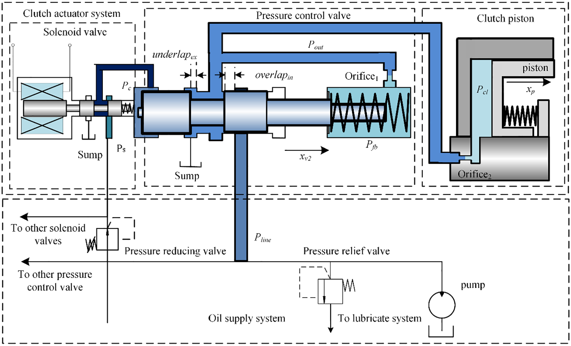
Schematic of a typical hydraulic system of automatic transmission.
Modeling of the solenoid valve
The solenoid valve can generate a control pressure in the left chamber of the pressure control valve proportional to the exciting current from the control unit. The steady input-output model of the solenoid valve is commonly used in the clutch control researches. The proportional solenoid valve utilized by this paper is developed by TECNORD® and the experimental steady state character of the valve is shown in Figure 2.

Static output character of the proportional solenoid valve.
Considering the response time of the solenoid valve, the dynamic response of the control pressure Pc can be expressed by combining the steady state character with a first order lag:
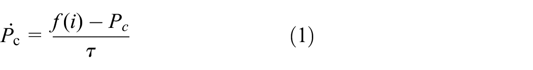
where f(i) is the steady state output pressure of the solenoid valve and can be modeled by a look-up table, τ is a time constant. The dynamic response comparison of the simulation and experimental results under a 0.3 A step control current are shown in Figure 3. The control current of the solenoid valve step increase from 0 to 0.3 A at 1.00 s and step decrease from 0.3 A to 0 at 2.00 s. The rising and decreasing time of solenoid valve output pressure are both 50 ms and agrees well with the simulation results with a time constant of 0.01 s. The experimental pressure have an overshoot at about 1.03 s. In this study, the oil temperature in the system is set to be 40°C. Different time constant can be set as a look up table to predict the dynamic response time of the solenoid valve under different working temperature.

Experiment and simulation results of the dynamic response of the solenoid valve.
Modeling of the pressure control valve
The dynamics of the pressure control valve can be established by the dynamics of the valve spool and the pressure flow dynamics in the clutch actuator system, which have been studied and verified in the previous study.31,32 The model of the pressure control valve can be expressed by a four dimensional state equation which represent the dynamic motion of the valve spool, the dynamics of the output and feedback pressure, which can be written as:

where mcv is the mass of the pressure control valve spool, xcv is the position of the valve spool,
Modeling of the clutch piston
Accordingly, the dynamics of the clutch piston can be expressed in a three dimension state equation as:

where xp is the displacement of the clutch piston, mp is the mass of the piston, Fpre is the preload of the piston spring, cp is the damping coefficient of the piston, kp is the spring rate of piston. Acl is the area of the piston. From equation (1) to (3), the system can be expressed as an eight-dimension dynamic system.
Model reduction of the hydraulic system
Since the computational expense of the full dimension model of the hydraulic actuator system make it hard to be utilized in the real time control system, a reduced order model of the hydraulic clutch actuator system, which can achieve a balance between model simplicity and accuracy basing on the energy-based nature of the system is proposed in this chapter.
Energy based analysis of the system
Energy based importance analysis is a commonly used method to identify the important state variable and parameters in energetic systems.33,34 The activity of each element in the system is the integral of the absolute value of its energy during a certain time interval:

where P is the power in the element and the unit is J. The activity index of an element is the ratio between the activity of the considered element and the total activity in the system, which can be expressed as:

The resistive power of spool and piston mass can be calculated by:

where ci is the damping coefficient and vi is the velocity of spool or piston.
The inertial power of spool and piston due to the motion of mass can be derived by Newton’s second law and expressed as:

where m is the mass of valve spool or clutch piston, a is the acceleration, and v is the corresponding velocity.
The resistive power of hydraulic chamber, valve port, and orifice can be calculated by:

where Pvin is the absolute pressure at the inlet port of the element, Qvin is the volumetric flow rate at the inlet port, Pvout and Qvout are the absolute pressure and volumetric flow rate of the output port.
The mechanical capacitance energy of springs can be calculated by:

where Fs is the spring force and Vs is the spring compression velocity.
During the gearshift of automatic transmission, the clutch pressure is controlled by the solenoid valve in about 1 s. The interest scenario is chosen as a sine wave input with 1 Hz frequency, which vary the clutch pressure between zero and the maximum pressure, shown in Figure 4.

The input current and hydraulic pressure of the interest scenario.
The calculated activity index result is shown in Figure 5. It can be seen from the figure that the orifice of clutch chamber, the inlet valve port, clutch piston chamber and the valve exhaust port have the most significant activity index, while the feedback chamber and clutch spring have the least effects on the system dynamics.

Calculated activity index of each element in the hydraulic system.
Reduced model of the cultch actuator system
Basing on the study of activity index, the system model can be reduced by neglect the inertial power of clutch piston, inertial power of valve spool, orifice 1 and feedback chamber. The reduced model of the system can be derived as follow.
The dynamics of the valve spool can be reduced by neglect the inertial power and expressed as:

By neglect the effect of the feedback orifice and feedback chamber, the feedback pressure can be regarded as the same with the output pressure, which can be expressed as:

The volume of feedback chamber is also considered in the calculation.
The clutch pressure Pcl can be expressed as:

where the flowrate Qcl can be expressed using the discharge equation as:

In summary, the dynamics of the system can be represented by a four-dimension state equation as:
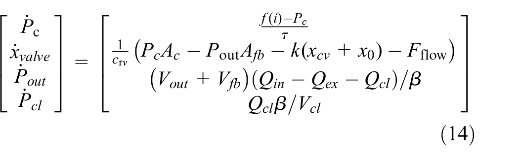
The comparison of the dynamic clutch pressure responses of the full order model and reduced order model of the hydraulic system is shown in Figure 6. The nominal system parameters used in the simulations are shown in Table 1. The dynamic response of the reduced order model shows a great agreement with the full order model. The biggest error appears during the rising phase of the clutch pressure, where the full order model shows a lag of about 7 ms. The comparison results indicate that the proposed reduced order model can represent the dynamics of the hydraulic actuator system with a satisfying accuracy.
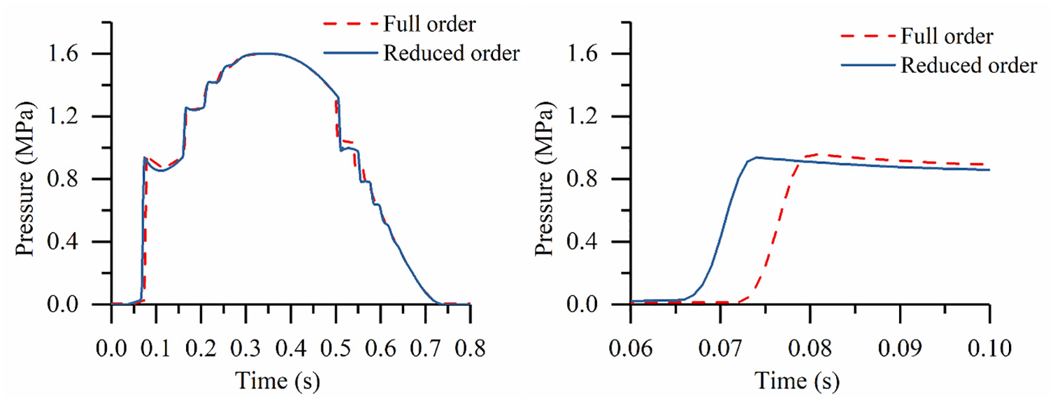
Comparison of the clutch pressure response between reduced order model and the full order model.
Nominal system parameters used in the simulations.

State observer design
The UKF algorithm is a model-based estimation algorithm which uses the current measured state to estimate the value of the current moment state on the basis of the model. An observer is proposed to estimate the state variables of the clutch actuator system with the signal of the output pressure of the pressure control valve, which is measureable on vehicle transmission.
Observer design
According to the proposed reduced order model of the hydraulic actuator system, the state equation of the system can be expressed as:

where the state variables are the variables in the left of equation (15) respectively, f(i) is the pilot pressure Pc, which is the input of the system, which is achieved by experimental results of the solenoid valve. Qin, Qex, Qfb, Qcl can be expressed as nonlinear equations of state variables according to Section “Working principle and modeling of the hydraulic clutch actuator system,” which can be represented by look up tables in the simulation.
Since many uncertain factors such as leakage and friction and measurement noise are included in practical cases, the state equation of the system can be expressed as:
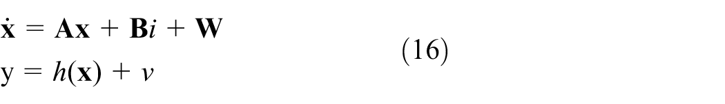
where
The process noise W is set as:
The five core equations of the Kalman filter are:

Since the Unscented Kalman Filter requires a discrete-time state transition function, Euler discretization method is utilized to approximate the continuous-time model of the system. Assume that your sample time is Ts, and denote the continuous-time dynamics as

where x[k+1] is the state of next time and x[k] is the state of the current time. Ts is the sample time. The resulting discrete-time state-transition function can be expressed as:

The function that describes how the model states are related to sensor measurements can be written in the form:

where h(x[k], u(k)) is the measurement function, v is the measurement noise, and u[k] is the system input current of the system.
The discretized state transition equation and the resulting model of the observer is established in the software Simulink and shown in Figure 7. The input signals of the estimation algorithm include the input current of the solenoid and the output pressure of the pressure control valve, and the function output is the state vector at the next step, calculated using the discretized state transition equations.

Simulation model of the proposed observer model.
Simulation results
The simulation results of the proposed clutch pressure observer in both step response and sine wave conditions are shown in Figure 8. Table 2 shows the parameters used in the Unscented Kalman Filter. Suppose the initial condition is unknown, the initial value of the states are set to be:

Simulation results of the proposed clutch pressure observer.
Parameters used in the Unscented Kalman Filter.

Experimental analysis
Experiments are carried out to verify the reduced order model of the system and the proposed clutch pressure observe method.
Experiment setup
The schematic sketch of the hydraulic test rig is shown in Figure 9 and the setup of test rig is shown in Figure 10. A constant flow of 160 L/min in the system is provided by an electric gear pump. The input line pressure of the pressure control valve is set to be 1.2 MPa. Pressure sensors PS1, PS2, PS3, and PS4 are mounted to measure the pilot operating pressure, feedback pressure, clutch pressure and output pressure of the pressure control valve, respectively. PS4 is on the back of the valve and cannot be shown in the test bench photo. The parameters such as fluid temperature and valve parameters are set to be identical to the simulation parameters.
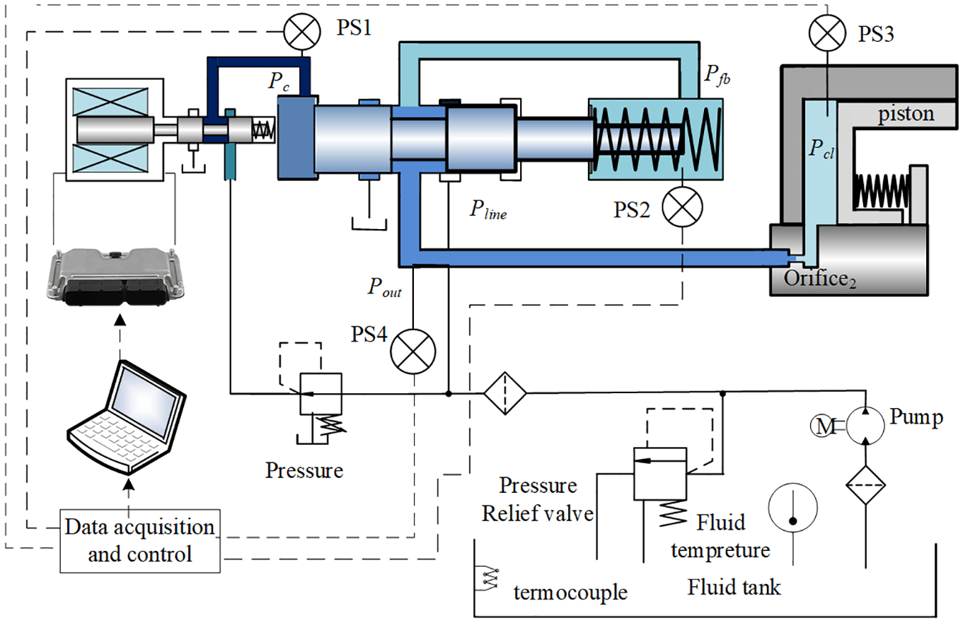
Experimental test rig.
Testbench of clutch pressure control system.
Verification of the dynamic model
A dynamic response experiment is carried out to verify the proposed dynamic model of the hydraulic clutch actuator system. Figure 11 shows the comparison between the experimental pressure response results. The response time of output pressure is about 0.1 s, which is the least. The response of the feedback pressure is slightly slower than the output pressure. During the filling phase of the hydraulic clutch, the value of feedback pressure is between the values of the line pressure and the output pressure of pressure control valve. At the end of the filling phase, the feedback pressure and output pressure increases along with the clutch pressure until the values of the three pressure equal to the line pressure. The decline response time of the valve of the feedback pressure is the least, which is about 40 ms while the decline time of the clutch pressure is about 60 ms. The simulation and experimental results are in good agreement. The difference between the simulation and experimental results may due to the leakage of valve clearance, which was not considered in the proposed model.
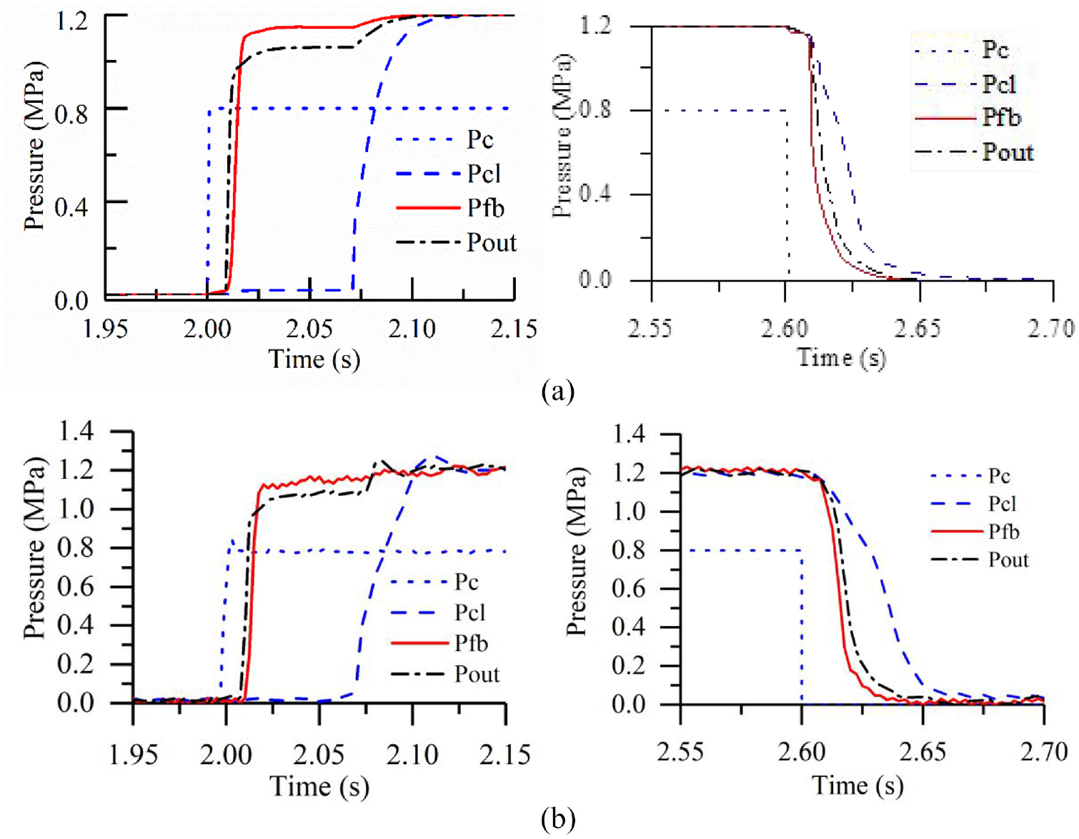
Simulation and experimental results of the dynamic response of the system: (a) simulation results of the pressures in the system, (b) experimental results of the pressures in the system.
Experimental results of the observer
Another experiment was carried out to validate the effectiveness of the proposed observer. The clutch pressure observe results of a clutch pressure trajectory are shown in Figure 12. The observe results during the clutch engaging process is shown in Figure 12(a) and the results during the clutch disengaging process is shown in Figure 12(b). During the clutch engaging process, there is an overshoot of about 0.125 MPa at the end of the filling phase. The observation error during both the engaging and disengaging process is less than 0.1 MPa. Basing on the experimental results, it can be concluded that the proposed clutch pressure observer is feasible for the application of transmission clutch pressure control.

Experimental results of the proposed clutch pressure observer: (a) observer experimental results during clutch engaging process, (b) observer experimental results during clutch disengaging process.
Conclusion
In this study, the dynamic model of a hydraulic clutch actuator system was established considering the inherent nonlinear flow characteristics coupled with the valve spool motion dynamics. A reduced order model of the hydraulic clutch actuator system is proposed basing on the activity index of each element in the system. It is verified by dynamic experimental results of the hydraulic clutch actuator system that the dynamic model can predict the pressure dynamic characters inside the hydraulic system, which can be used in the observer of the system. An UKF based clutch state observer is proposed to estimate the clutch pressure using the real time signal of the output pressure of the pressure control valve. Uncertain factors and measurement noise are taken into consideration. The simulation and experimental results of the observer indicate that the maximum observation error is less than 0.1 MPa during the tracking control process. In conclusion, the pressure observe method proposed in this study provides a practical method in the feedback control of the clutch actuator system during both single transition and double transition gear shift process, which can be widely used in kinds of vehicle transmission systems. This could provide important instructions to the engineers and researchers of automatic transmission control. Further work will include the filling control of clutch actuator system and optimization of clutch pressure curve to achieve a superior shift quality.
Footnotes
Acknowledgements
N/A
Handling Editor: Dr Sharmili Pandian.
Declaration of conflicting interests
The author(s) declared no potential conflicts of interest with respect to the research, authorship, and/or publication of this article.
Funding
The author(s) received no financial support for the research, authorship, and/or publication of this article.