
Abstract
This article develops the model of a connected multi-car train system and discusses the improvement of stability and performance by the inerter. The inerter is a genuine two-terminal element, whose reacting force is proportional to the relative acceleration across its terminals. First, we build a 31-degree-of-freedom full-train model by a multi-body package, called AutoSim, and show that its stability can be significantly improved by the inerter. Second, we derive a multi-car train model, by another multi-body package, called SimMechanics, and discuss the impacts of the number of connected cars on system stability: connecting cars tends to decrease the critical speed. Furthermore, we extend the discussion to performance and show that the connecting cars will increase the settling time, but has no influence on the passenger comfort. Finally, we apply network synthesis methods to realize a mechatronic network and conduct experimental verification. Based on the results, the inerter is deemed effective in improving the stability and performance of connected multi-car trains.
Introduction
Analogies between mechanical and electrical systems have drawn much attention and led to the invention of the inerter. 1 The inerter is proposed to be the substitute for the mass element, with the reacting force proportional to the relative acceleration of its two terminals. The introduction of the inerter lets mechanical networks become truly analogous to electrical ones. Consequently, all passive mechanical networks can be constructed by inerters, dampers, and springs, and the performance of mechanical systems can now be improved passively (i.e. without consuming extra energy). There are several mechanical realizations of inerter, including the rack-pinion inerter, 2 the ball-screw inerter, 3 the hydraulic inerter, 4 and the mechatronic network. 5 Among these, the first three are pure mechanical constructions, whereas the fourth consists of a ball-screw inerter and a motor generator so that the system impedance/admittance can be easily adjusted by the electrical networks.
The inerter has been successfully applied to vehicle suspensions, 2 motorcycle steering, 6 and building models. 7 The results confirmed the significant improvement on system stability and performance by implementing the inerter. Many studies have also discussed the stability and performance of train systems employing the inerter. For example, Wang and Liao 8 discussed the stability of a 16-degree-of-freedom (DOF) train model. Wang et al. 9 further considered the performance improvement of the train model with the inerter. Jiang et al. 10 investigated the lateral passenger comfort. The effects of inter-vehicle connections are studied based on multi-body dynamics theory. For instance, Ling et al. 11 discussed the impacts of vehicle connections on the dynamic behavior of train models. They compared the dynamic performances of the single-car and the multi-car train models without the inerter. This article extends the discussion to train models with the inerter. We built the single-car and multi-car train models in AutoSim and SimMechanics, respectively. Because there has been no profound discussion on how connected cars might influence system stability and performance using inerters, in this article, we apply the models to discuss how the number of connected cars could influence the stability and performance of trains employing inerters.
The main contributions of this article are as follows: we developed a 31-DOF full-train model that included the pitch motions of the car body and bogies, and we constructed multi-car train models to investigate the impacts of connecting cars on stability and performance of the system employing the inerter. This article is arranged as follows: in section “The 31-DOF full-train model,” we derive a 31-DOF full-train model. We then apply seven suspension layouts to discuss how the model stability can be improved by the inerter. Section “Connected multi-car train model” derives multi-car train models and discusses the impacts of connecting cars on the critical speed, settling time, and passenger comfort. Section “Network synthesis” realizes an optimal electrical circuit and conducts experimental verification. Finally, we draw conclusions in section “Conclusion.”
The 31-DOF full-train model
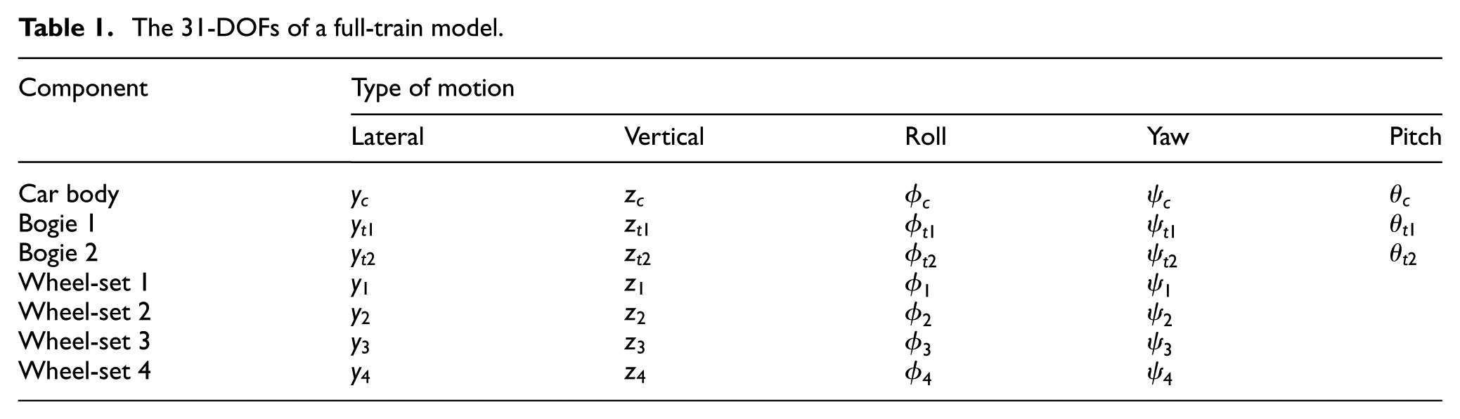
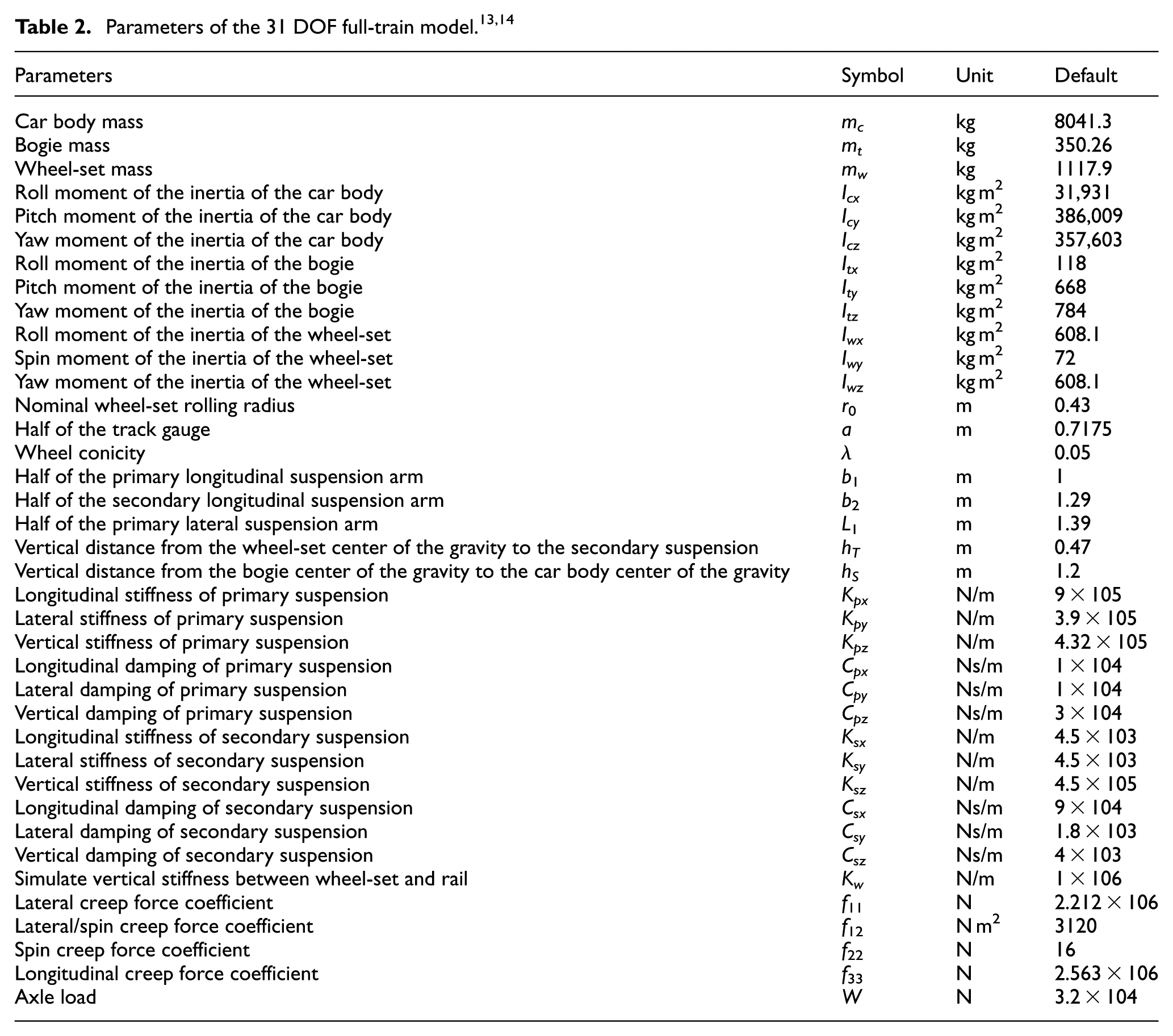
The full-train model is shown in Figure 1, which consists of a car body, two bogies, and four wheel-sets. We assume a constant forward velocity and neglect the longitudinal (x-direction) motions, and derive a full-train model that has 31 DOFs (see Table 1) with the default parameters as illustrated in Table 2. The full-train model consists of two main suspensions. The primary suspension is between the bogie and the wheel-sets, denoted Qpx, Qpy, and Qpz in the x-, y-, and z-direction, respectively. The secondary suspension is between the car body and the bogie, denoted as Qsx, Qsy, and Qsz in the x-, y-, and z-direction, respectively.

The 31-DOF full-train model. 12
The 31-DOFs of a full-train model.
The dynamic equations of the full-train model are shown in Appendix 1. We also build the full-train model by a multi-body package, called AutoSim (see Appendix 2), for model verification. We derive the following linearized hand-derivation model (

We compare the elements, eigenvalues, and singular values of the two system matrices (
Suspension layouts employing the inerter
The dynamics of an inerter is as follows 1
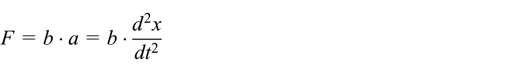
where F is the reacting force, a is the relative acceleration between two terminals, b is the inertance (kg), and x is the relative displacement between two terminals. However, the mechatronic network (see Figure 2(a)) consists of a ball-screw inerter and a permanent magnet electric machinery (PMEM) with an electrical circuit, such that the system admittance is a combination of mechanical and electrical systems as follows 5
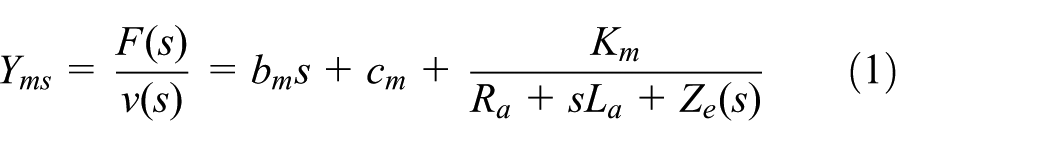
with the equivalent network of Figure 2(b). The right-hand side of equation (1) can be separated into two parts. The first part,

Mechatronic network: 5 (a) a prototype and (b) the network representation.
We consider seven basic suspension layouts, as illustrated in Figure 3, where F represents the suspension force and v is the relative velocity between two terminals, to discuss the improvement of system stability by inerters. S1 is the conventional suspension. S2 and S3 are the basic parallel and serial arrangements with inerters, respectively. MS1 is a parallel arrangement with the mechatronic network, and MS2–MS4 are the serial arrangements with the mechatronic network. Note that these suspension layouts represent basic element arrangements. More complex layouts are possible by considering the general system impedance and network synthesis, as shown in previous studies.15–17

Seven suspension layouts—(a) S1:
Stability analysis: the critical speed
We now discuss the benefits of inerters in improving the stability of the full-train model. The stability of trains is dominated by the hunting phenomenon, which is caused by the oscillations of the wheel-sets due to the radius variation between the inner and outer sides of wheels. When the train exceeds a critical speed, the hunting motion becomes severe, so that the train could become unstable and run off the tracks. 18 Therefore, we will investigate how the critical speed can be improved by the proposed inerter layouts, especially the mechatronic networks.
The critical speed

where
Improvement of Vcr by inerter layouts at individual suspension locations
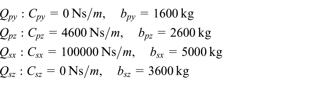
We replace the parallel spring–damper struts of Figure 1 by the proposed inerter layouts and apply the parameters of Table 2. We fix the spring stiffness and optimize other suspension parameters for the critical speed. In addition, we limit the damping rates to less than 100 kNs/m and inertances to less than 5000 kg for practical implementation, and use the following motor constants: Ra = 2.3 Ω, La = 0.7 mH, and Km = 70560 VNs/A/m from Wang and Chan 5 for the mechatronic inerter layouts. The optimization results are shown in Table 3. First, the critical speed can be significantly improved by implementing S2 at Qpy (8.00%), Qpz (16.12%), Qsx (26.64%), or Qsz (21.63%) with the following suspension parameters
Critical speed (km/h) by individual suspension layouts.

Note: The bold values are used to specify that they are the optimal in all layouts (or the simple layouts S1~S3).
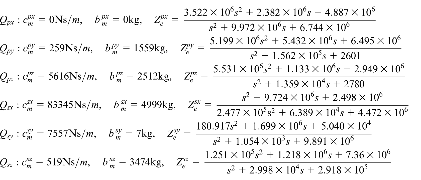
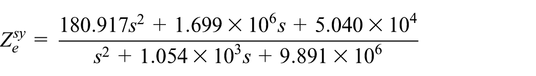
Second, S3 has less influence on the critical speed because the serial layout tends to have more benefits for stiff systems, but the train suspensions are relatively soft. 2 Finally, the critical speed can be further improved by mechatronic networks, especially MS1, with the following suspension settings
Improvement of Vcr by inerter layouts at all suspension locations
From Table 3, we note that the critical speed can be significantly improved by the mechanical inerter layout (S2) and the mechatronic inerter network (MS1). Therefore, we now apply S2 and MS1 to all six suspension locations to further improve the critical speed. Because the numbers of adjustable parameters are 12 for S2 and 42 for MS1, we applied the particle swarm optimization (PSO) method 19 to achieve the maximum critical speed. The results are illustrated in Table 4, where the critical speed by S1 might be increased to 1413 km/h by optimizing the corresponding damper settings. In addition, the critical speed can be theoretically further improved to 2846 and 3754 km/h by S2 and MS1, respectively. Note that these speeds might not be practical because the inerter cannot be implemented on all suspension struts and system performance needs to be considered as well. That is, the design achieves good stability but might result in very poor performance, such as passenger comfort. We will discuss how the improvement will be influenced by connecting train cars and by considering performance in the next section.
Optimization of the critical speed by S2 and MS1 at all suspension locations.

Connected multi-car train model
This section extends the discussion to connected multi-car trains, because trains are normally connected in transportation application. The multi-car train model is developed by connecting the single-car trains via parallel spring and damper. We will discuss how the number of connected cars influences system stability and performance. The junction of cars can be represented as shown in Figure 4, where the cars are connected by an equivalent lateral spring with Kby = 20 kN/m located at hk = 0.75 m and an equivalent lateral damper with Cby = 50 kNs/m located at hc = 1.5 m above the center of gravity of the car body. 20

Modeling of restriction between car bodies. 20
In section “The 31-DOF full-train model,” we built the single-car train model using AutoSim. However, we cannot connect more than two cars together in AutoSim because of its element limitation. Therefore, we use another multi-body package, called SimMechanics, to build the connected multi-car train model and compare it with the hand-derived model for verification. First, we derive the dynamic equations of a 12-car train model with 372 DOFs, as illustrated in Appendix 3, and obtain the linearized model,

Second, we construct the 12-car train model in SimMechanics, as shown in Appendix 4, and obtain the linearized model,

For model verification, we compare the system matrices,
Influences on the critical speed by the number of cars
We note from Table 4 that the critical speed of a single-car train can be significantly improved by inerter layouts S2 and MS1. Now, we will discuss how the improvement is affected by the number of connected cars. Applying the parameters of Table 4, the critical speed of multi-car trains is shown in Figure 5, where the critical speed is reduced as the number of connected cars increases. For example, the critical speed is dropped from 2846 km/h (1car) to 1727.7 km/h (12 cars) using S2, and from 3754 km/h (1car) to 1179.4 km/h (12 cars) using MS1.

Critical speed versus the number of connected cars: (a) S2 and (b) MS1.
Impacts on the performance
We now discuss the improvement of system performance, such as settling time and passenger comfort, using the inerter layouts. The results illustrate the compromises made in suspension settings between system stability and performance. First, the settling time is defined as the time required for the system responses

Because the settling time significantly increases when the forward velocity is greater than 1500 km/h, we define the following cost function for settling-time optimization

That is, we adjust the suspension parameters to reduce the settling time at 10 different velocities. We set the velocities as linearly spaced between 1500 and 0.9
Another important performance index, called the Passenger comfort, is defined as the 2-norm of the transfer function from the road profile to the vertical velocity of the car 9

where

where
Optimization of

We now further discuss the influences of connecting cars on system stability and performance. Using the parameters of Table 5, the impacts of the number of cars on the critical speed, settling time, and passenger comfort are shown in Figure 6. First, the critical speed drops from 606 km/h (1 car) to 582.1 km/h (12 cars) using S2 (see Figure 6(a)), and from 1675.9 km/h (1 car) to 841.7 km/h (12 cars) using MS1 (see Figure 6(b)). Although MS1 has a larger degradation (about 50%) than S2 (about 4%), its achievable critical speed is still much higher than S2. Second, the settling time tends to increase when the number of cars increases. For example, at a forward speed of 400 km/h, the settling time increases from 9.9 s (1 car) to 28.5 s (12 cars) using S2 (see Figure 6(c)), and from 2.5 s (1 car) to 8.0 s (12 cars) using MS1 (see Figure 6(d)). Finally, the passenger comfort is shown to be significantly improved by the inerter. However, it is independent of the car numbers (see Figure 6(e) and (f)), because only the vertical suspensions (i.e. Qpz and Qsz) can influence the passenger comfort J1, while the connecting spring–damper is set horizontally and does not change the vertical dynamics of the linear models. Note that we only consider these three indexes to demonstrate the benefits of inerters. Other performance 10 might also be evaluated in the similar way.

Impacts of car numbers on stability and performance: (a) critical speed by S2, (b) critical speed by MS1, (c) settling time by S2, (d) settling time by MS1, (e) passenger comfort by S2, and (f) passenger comfort by MS1.
Network synthesis
The mechatronic network is shown to improve stability and performance of the train systems. In this section, we will show how to realize the designed impedance
This circuit can be realized by the method in Jiang and Smith 17 to be a five-element circuit of Figure 7 with the following parameters


Network realization of
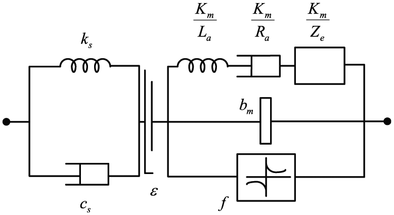
We will now discuss the nonlinearities of the mechatronic network and construct experiments for verification. The nonlinearity of the mechatronic network includes the elastic effects, backlash, and friction, as shown in Figure 8, where ks and cs are the elasticity and viscous damping, respectively,

where Fc and Fs are the Coulomb friction and static friction, respectively,
Nonlinear mechatronic network model.
We design a vertical platform, as illustrated in Figure 9, to identify the system parameters. First, we set the circuit impedance

Testing platform.
We constructed

Responses of the models: (a) time responses (2 Hz), (b) time responses (10 Hz), and (c) frequency responses.
Conclusion
This article has discussed the benefits of inerters for a connected multi-car train model. First, we built a 31-DOF full-train model by hand derivation and AutoSim, and showed the improvements in critical speed by the inerter. Second, we derived a connected multi-car train model by SimMechanics for verification and demonstrated that car connection can decrease the critical speed. Furthermore, we extended the discussion to performance and showed that connecting cars can increase the settling time, but have no influence on the passenger comfort. Finally, we realized one optimal electrical circuit of the mechatronic inerter by network syntheses and conducted experimental verification. Based on the results, the inerters are deemed effective in improving the stability and performance of the connected multi-car train systems. In the future, the results can be applied to design suspensions for different types of train models, for example, the passenger rail vehicle in Hirotsu et al. 14 that has much higher mass and inertia. Furthermore, we considered the model nonlinearities and discussed their effects on system performance to estimate the practical applications. Finally, experiments should be conducted to verify the effectiveness of the inerter on train systems.
Footnotes
Appendix 1
The dynamic equations of the 31-DOF train model is available on: http://140.112.14.7/~sic/PaperMaterial/Dynamics_of_a_Train_model.pdf
Appendix 2
The AutoSim codes of the 31-DOF full-train model is available on: http://140.112.14.7/~sic/PaperMaterial/AUTOSIM_CODE_31-DOF_Full-train_Model.html
Appendix 3
The derivation of a 12-car train model is available on: http://140.112.14.7/~sic/PaperMaterial/Derivation_Twelve-car_Train_Model.pdf
Appendix 4
The SimMechanics model of a 12-car train is available on: http://140.112.14.7/~sic/PaperMaterial/SimMechanics_Model_Twelve-car_train.html
Academic Editor: Xiaoting Rui
Declaration of conflicting interests
The author(s) declared no potential conflicts of interest with respect to the research, authorship, and/or publication of this article.
Funding
The author(s) disclosed receipt of the following financial support for the research, authorship, and/or publication of this article: This work was supported in part by the National Science Council of Taiwan under grant no. 95-2218-E-002-030.