
Abstract
The inerter emerged as a mechanical analogy to the electrical capacitor, completing the force-current analogy. It operates as a one-port, two terminal device, where the equal and opposite forces at its terminals correlate with the relative acceleration between them. This relationship is governed by ‘inertance’, a quantity that bears the unit of mass, allowing inerters to exert inertial forces. Inerters have gained considerable traction, particularly in vibration control applications. Derived from their passive counterparts, variable inertance inerters enable active control of their inertance through integrated control mechanisms. This work presents the design, modelling and evaluation of a variable inertance inerter prototype dubbed the ‘Variable Inertance Bypass Fluid Inerter’ (VIBFI). An experimental prototype of the concept was designed, constructed and tested. Simultaneously, an effort to develop and validate a mathematical model of the VIBFI is thoroughly documented. Experimental results demonstrate the controllability of performance parameters of the device, including inertance and damping coefficients, through modulating the flow restriction of the bypass channel. The mathematical models derived for the device can serve as an estimate for its performance parameters, though further refinement is required.
1. Introduction
Proposed in the early 2000s, the Inerter is a one-port, two terminal mechanical device that exerts inertial force proportional to the relative acceleration of their terminals. This proportional relationship is governed by ‘inertance’, which is a constant that carries the unit of mass (Smith, 2002). An inerter stores kinetic energy when a load causes relative motion between its terminals. Upon the release of this load, the stored energy gets released, inducing motion at the inerter’s terminals, enabling them to exert inertial force. The inerter is considered as a mechanical equivalent of the electrical capacitor to complete force-current analogy (Smith, 2002). Inerters exhibit negative stiffness and have mass amplification capability. The negative stiffness exhibited by an inerter is proportional to its inertance (Ma et al., 2021). These properties enable inerters to lower the natural frequencies of mechanical systems (Ma et al., 2021) or exert the inertial force of a large mass using a lightweight device (Smith, 2002).
Inerters can be physically embodied by coupling a transmission mechanism into an inertial energy storage mechanism. An example of such embodiment can be illustrated through a rack and pinion inerter, where a rack and pinion transmission mechanism is coupled to a flywheel for kinetic energy storage (Smith, 2002). Over the last two decades, various other embodiments of the inerter have been emerged in literature. They include, but are not limited to, ball-screw inerter (Papageorgiou et al., 2009), gear pump (hydraulic) inerter (Wang et al., 2011), helical fluid inerter (Swift et al., 2013), living hinge inerter (John and Wagg, 2019) and electromagnetic inerter (Gonzalez-Buelga et al., 2015). Each configurations have their unique strengths and limitations, making them suitable for specific applications. Realistic devices can only approximate the behaviour of the ideal inerter if they satisfy the following conditions: have small physical mass relative to its the inertance; be detachable from physical grounds; have specified linear travel and adherence to the force-acceleration proportionality relationship even when the direction of terminal motion is reversed (Smith, 2002, 2020). Realistic inerters suffer from nonlinearities such as dry friction, viscous damping, backlash and material compressibility or elasticity (Chillemi et al., 2023; Li et al., 2012; Ma et al., 2021; Wang and Su, 2008). These nonlinearities can deviate actual performance from ideal models and negatively affect performance in various applications (Brzeski and Perlikowski, 2017; Gonzalez-Buelga et al., 2017; Wang and Su, 2008).
The inerter was originally developed to be a component of the suspension network of high-performance vehicles. Incorporation of the inerter in vehicle suspension systems improves handling, ride comfort and suspension travel leading to an enhanced performance in the vehicle (Smith and Wang, 2004). Since its introduction, applications of the inerter have continuously expanded. Vibration control is a popular application of the inerter. Inerter-based vibration control systems modulate the inertial properties of the structure in addition to the stiffness and damping properties, resulting in better performance compared to conventional vibration control systems with only stiffness and damping components (Ma et al., 2021). Inerter-based vibration control systems have been studied in various applications, which includes but are not limited to structural vibration control (Ma et al., 2021), railway vehicle suspension (Wang et al., 2009), steering systems (Evangelou et al., 2007) and landing gear shimmy vibration control (Li et al., 2017).
Passive inerters feature fixed inertance, while variable inertance inerters allow adaptive control of their inertance via changing their inertance through auxiliary control systems. Chen et al. (2014) first proposed the concept of a variable inertance inerter with controllable inertance after considering the significant benefits of incorporating controllable dampers into vehicle suspension. Brzeski et al. (2015) introduced the first physical embodiment of the variable inertance inerter, integrating a continuously variable transmission between the rack-and-pinion and the flywheel of a rack-and-pinion inerter. Since its introduction, the variable inertance inerter has been employed to improve performance in structural vibration control (Brzeski et al., 2015; Hu et al., 2016; Sadeghian et al., 2021, 2022), vehicle suspensions (Chen et al., 2014; Hu et al., 2017; Li et al., 2021; Zhang et al., 2018), seat suspensions (Ning et al., 2019a, 2019b) and energy harvesting applications (Nemoto et al., 2022; Takino and Asai, 2023).
Various other configurations of the variable inertance inerter have also emerged. Based on passive ball-screw inerter, Hu et al. (2016) implemented a variable inertia flywheel to develop a variable inertance inerter. Zhong et al. (2020) implemented a magnetorheological (MR) clutch between two concentric flywheels to create a variable inertia flywheel for controlling the inertance of a ball-screw inerter. Yu et al. (2021) proposed a variable inertance gear pump inerter of which a parallel bypass channel with MR valve was integrated to control inertance. Zhang et al. (2018) proposed a variable inertance helical fluid inerter configuration which used a hydraulic cylinder-like ‘displacement-dependent inertance valve’ to control the inertance by modulating the effective length of the helical channel that the working fluid must flow through to store energy. The authors later conducted experimental verification of their device (Zhang et al., 2022). Tipuric et al. (2018, 2019) conceptually proposed a variable inertance helical fluid inerter by paralleling an MR valve with the helical channel. Its inertance can be controlled by regulating the current supplied to the MR valve. However, this design have not been prototyped and experimentally verified. Beside, the use of MR fluids also bring the concern of sedimentation for long term usage.
In light of the above motivation, this paper presents the design, modelling and experimental evaluation of a novel variable inertance inerter termed the ‘variable inertance Bypass Fluid Inerter (VIBFI)’. The VIBFI operates by directing flow through a helical channel using a hydraulic cylinder to generate inertance effects. Its inertance can be controlled by modulating the ratio of flow rates between the helical channel and the hydraulic cylinder, facilitated by a parallel bypass channel equipped with a proportional flow control valve. In comparison to existing variable inertance inerters featuring displacement-dependent inertance valves (Zhang et al., 2018, 2022), the VIBFI offers a simpler and more space-efficient design. It eliminates the necessity for a secondary hydraulic cylinder-like valve structure and the associated grounding space required for inertance control mechanisms. While sharing similarities with the proposed MR bypass inerter concept (Tipuric et al., 2018, 2019), the VIBFI utilises conventional Newtonian working fluids like hydraulic oil or water instead of MR fluids, as well as a proportional flow control valve instead of an MR valve for controlling inertance. These design choices evade common drawbacks associated with MR fluids, such as sedimentation and oxidation of magnetisable particles over time (Kumar et al., 2019). Furthermore, the experimental evaluation of this variable inertance inerter configuration addresses a gap in the literature, as previous studies have not experimentally assessed the concept of inertance control of a helical fluid inerter using a variable bypass channel (Tipuric et al., 2018, 2019).
The ultimate objective of this study is to present a configuration of the variable inertance inerter featuring controllable inertance, accompanied with a functional prototype and a reliable mathematical model that can be implemented for design optimisation and integrated into simulations of mechanical systems. To achieve this aim, the design of the VIBFI was proposed, and its mathematical model of the device was derived. Subsequently, the prototype was fabricated, and its performance was evaluated experimentally. The experimental results were then used to validate the mathematical model of the device by comparison against results simulated from the mathematical model. In this paper, Section 2 covers the conceptual design, working principles, mathematical model and prototype design of the VIBFI. Section 3 outlines the methodologies for experimental and simulation studies, Section 4 presents the results, and Section 5 discusses the results, while Section 6 concludes the paper, highlighting future work to be completed.
2. Concept and design of the variable inertance bypass fluid inerter
2.1. Concept and working principles
The variable inertance bypass fluid inerter (VIBFI) was developed from the passive helical fluid inerter, which generates its inertance effect from the circular motion of fluid in a helical channel (Swift et al., 2013). As shown in Figure 1, the VIBFI consist of a hydraulic cylinder, helical channel and a bypass channel with integrated flow control valve. Terminal 1 of the VIBFI is located on the housing of the hydraulic cylinder, while terminal 2 of the device is located on the rod end of the hydraulic cylinder. The chambers of the hydraulic cylinder are linked through a parallel network formed by the helical and bypass channels. The cylinder, the helical and the bypass channels are filled with the working fluid.
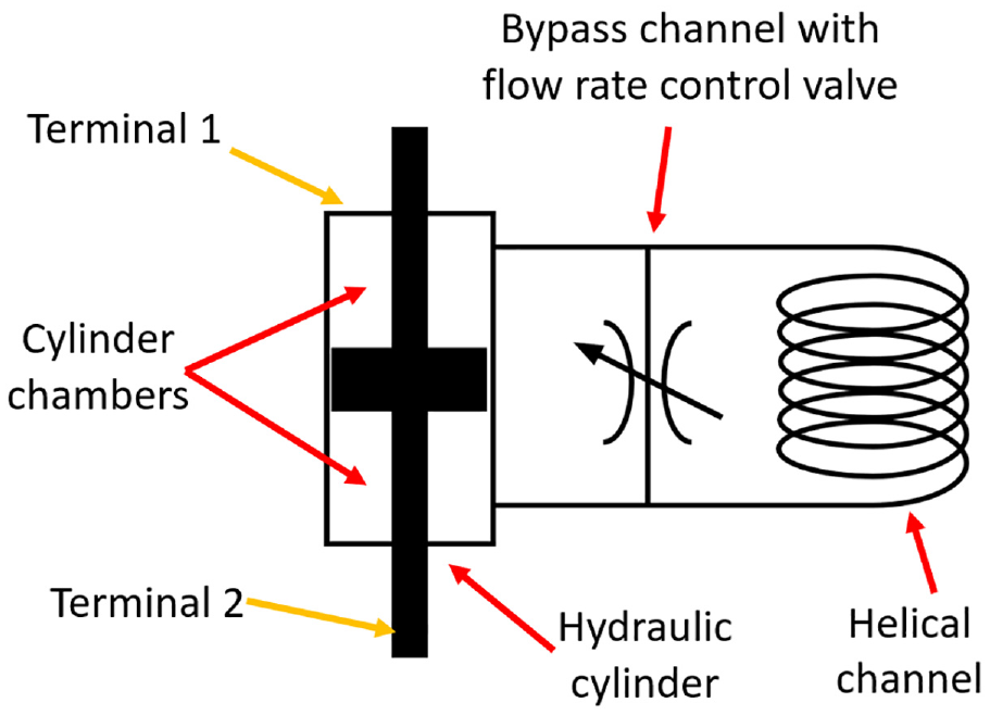
Schematic of the semi-active fluid bypass inerter.
The working principle of the VIBFI is described as follows. Relative movement between the inerter’s terminals induced by applied load causes fluid to flow from one chamber of the cylinder to the other via the parallel network formed by the helical and bypass channels. The circular motion of the working fluid through the helical channel stores kinetic energy, functioning as a fluid flywheel to exert inertial forces at the inerter’s terminal. Figure 2 shows the flow direction of the working fluid when applied load to the terminals induces relative motion between the rod and the cylinder.
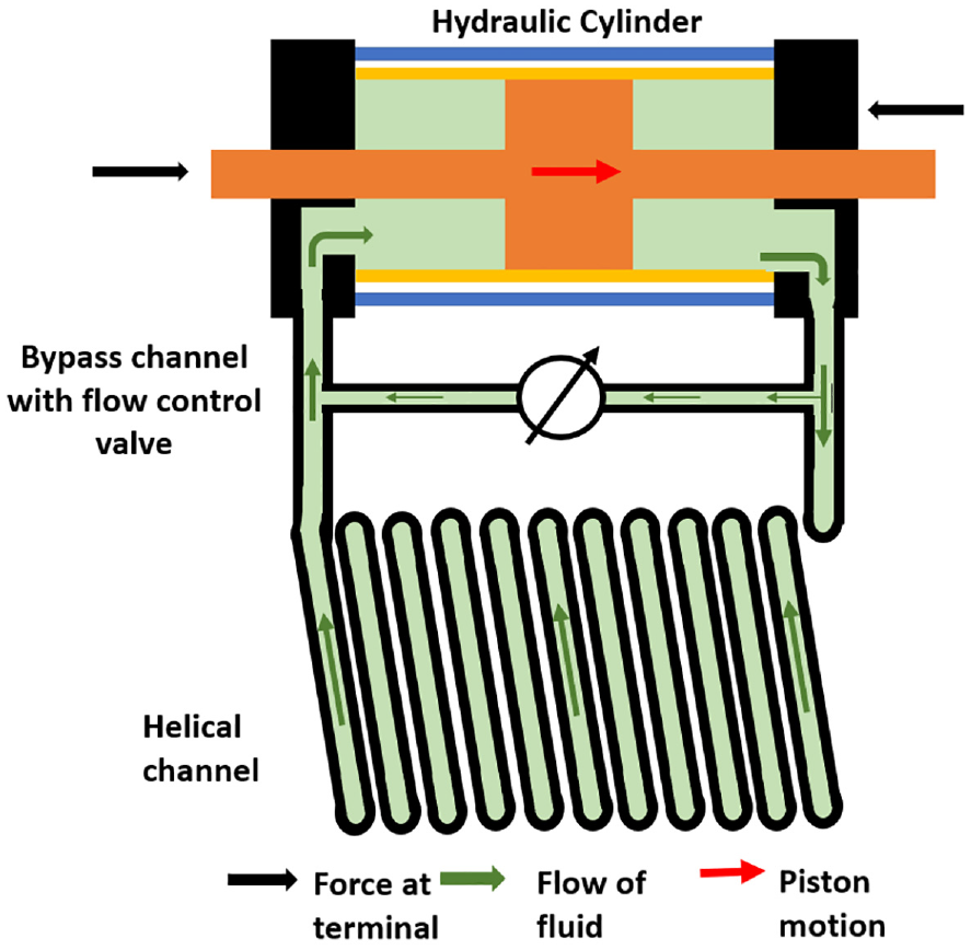
Schematic of the VIBFI, showing the flow of working fluid.
The inertance of the VIBFI can be adjusted by controlling the flow rate ratio between the helical channel and the hydraulic cylinder. A higher flow rate ratio implies that more fluid flows through the helical channel for every stroke of the cylinder, resulting in a higher inertance, and vice versa. This control is executed by modulating the flow restriction through the bypass channel, which is achieved by controlling the opening of the flow control valve. Assuming steady flow through the hydraulic system of the VIBFI, increased flow restriction in the bypass channel leads to a higher flow rate through the helical channel. This is because the flow of fluid naturally seeks the path of least resistance in a parallel pipe network. Conversely, when the flow restriction at the bypass channel is low, more fluid flows through it, resulting in a lower flow rate through the helical channel. This variation influences the flow rate ratio between the helical channel and the hydraulic cylinder, consequently affecting the inertance of the VIBFI.
Variation of the flow rate ratio in the VIBFI not only affects the inertance, but also the damping coefficient of the device. This is because the flow of fluid from one chamber of the cylinder to another via the parallel network of channels is subjected to a pressure drop that is also dependent on the flow rate ratio. This makes the VIBFI to feature both variable inertance and variable damping within a single device. Due to the configuration of the helical and the bypass channel, there are always flow of fluid through the helical channel irrespective of the position of the flow control valve in the bypass channel. This is a fail-safe feature of the VIBFI as it enables the device to function as a passive fluid inerter even if the flow control valve is faulty or inoperative.
2.2. Mathematical model
The VIBFI is modelled as a parallel network consisting of a variable inerter a variable damper, and a dry friction component as shown in Figure 3.
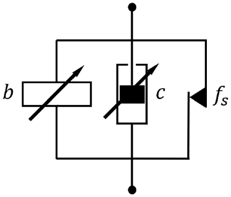
Mechanical network if the variable inertance bypass fluid inerter.
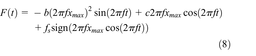
The output force

where
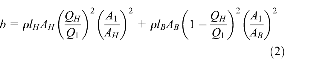
where
The damping effect in the semi-active fluid bypass inerter arises from the pressure drop across the hydraulic cylinder’s chamber
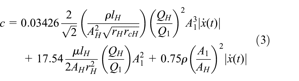
where
2.3. Design and prototype
The experimental prototype of the variable inertance bypass fluid inerter was designed and fabricated for this work. Figure 4 presents the CAD model of the variable inertance bypass fluid inerter, while Figure 5 presents the experimental prototype.
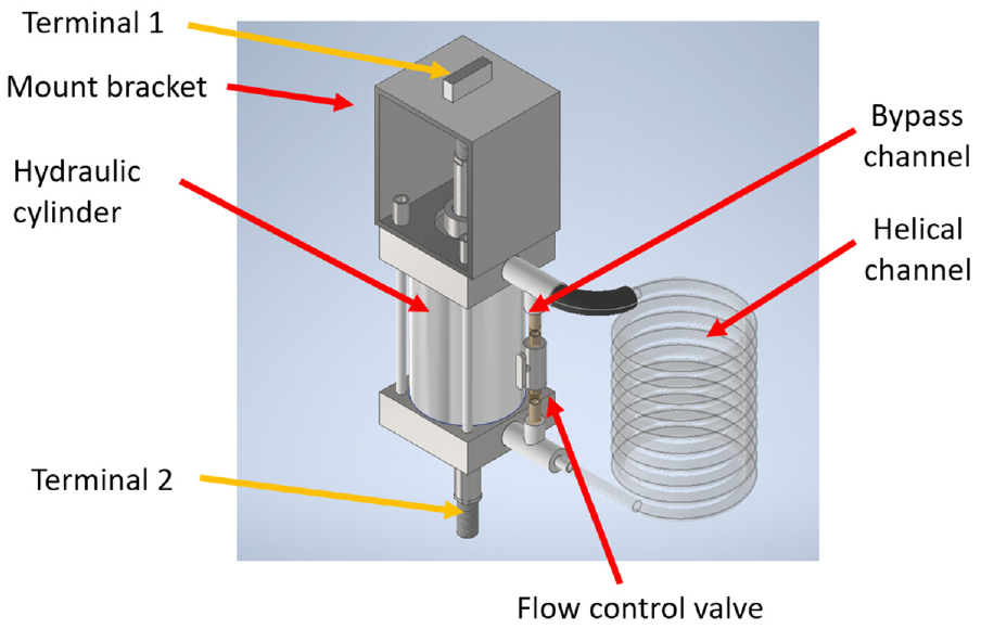
CAD model of the variable inertance bypass fluid inerter.
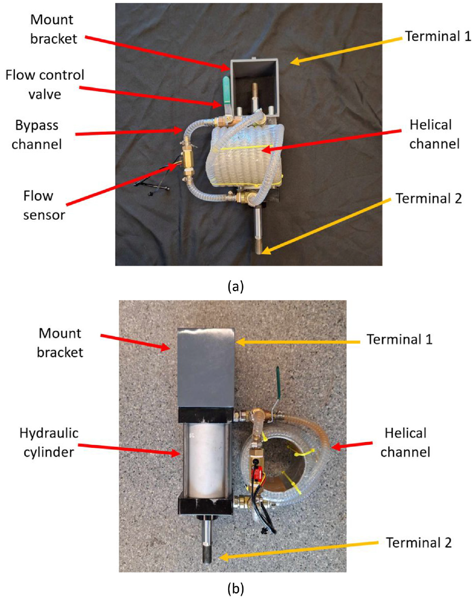
Experimental prototype of variable inertance bypass fluid inerter. Subfigures (a) and (b) depicts different views of the prototype.
The prototype was constructed using a combination of off-the-shelf and custom-made components. An off-the-shelf double-rod, double-acting cylinder was employed. A custom-made mount bracket was assembled to the cylinder. Wire-reinforced clear tubing was selected for constructing the helical and bypass channels due to its ease of forming a helical coil, while also maintaining the necessary strength and rigidity. This clear tubing also facilitated the detection of air bubbles in the hydraulic system, which should be avoided in practical applications. The helical channel was created by coiling this tubing around a rigid aluminium cylinder. For plumbing the system, standard threaded connectors were used. A hall effect flow sensor (model: YF-B7) was integrated into the bypass channel to monitor the flow rate, from which the inerter’s flow rate ratio was derived. A manually operated ball valve was used to adjust the flow rate across the bypass channel, thereby controlling the device’s inertance.
According to the mathematical models of the VIBFI, the ideal working fluid should possess high density and low viscosity to prioritise inertial forces over damping forces. Using high viscosity fluids would enhance viscous damping, hindering the desired inertial effect of the device. Additionally, low compressibility is crucial to avoid introducing an elastic-like effect akin to connecting a low-stiffness spring in series with the VIBFI. Water was employed as the working fluid for its availability, cleanliness, incompressibility and low viscosity. A method was adopted to fill the fluid inerter system with water that minimised air entrapment, ensuring optimal performance of the hydraulic system.
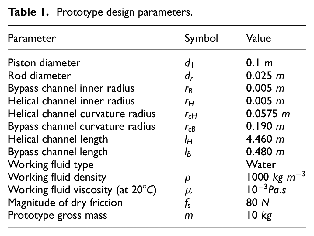
Table 1 outlines the design parameters of the device, including primary dimensions and fluid properties.
Prototype design parameters.
3. Experimental and simulation methodology
3.1. Overview
Experimental and simulation studies were conducted to evaluate the VIBFI’s performance and validate its mathematical models. The prototype was tested under steady-state sinusoidal displacement excitation at its terminals, of which the displacement

with
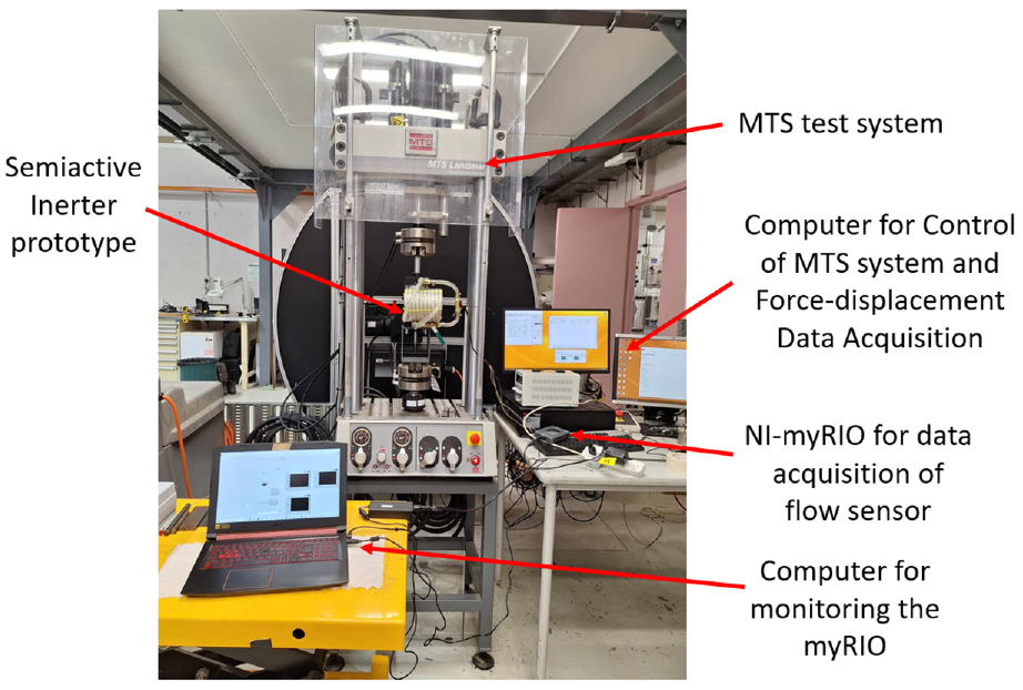
Experimental setup of semi-active fluid inerter.
Simulations were conducted using MATLAB to validate the mathematical models of the VIBFI. The models of the inerter were implemented into the MATLAB program, subjecting to the sinusoidal excitations and independent variables identical to those used in the experiments. Experimental and simulation results were then compared against each other. The mathematical model of the device is validated if experimental results align with simulations closely.
3.2. Experimental procedures
The inerter prototype was installed to the MTS system such that its first terminal was fixed, while its second terminal was subjected to sinusoidal excitation. The MTS system was programmed to exert sinusoidal displacement excitation such that the amplitude and frequency were adjustable by the operator. To investigate the effect of different oscillation frequencies on the prototype’s performance parameters, three frequencies − 0.4, 0.8 and 1.2 Hz were tested. For each frequency, the amplitude was maintained at 5.0 mm. At each excitation condition, 10 different flow rate ratios
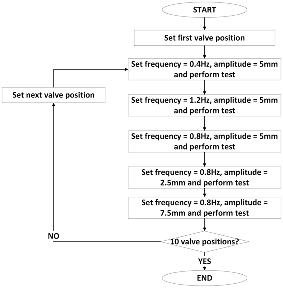
Flow chart showing the process of controlling the independent variables in the experiment.
Each change in the independent variables is referred to as a ‘data point’. At each data point, the force-displacement response ellipse of the inerter was recorded as its terminals undergo sinusoidal displacement excitation. Data from these force-displacement response ellipses were then being processed to evaluate the performance of the VIBFI at each data point. Simultaneously, the flow sensor records the volume of fluid that flows through the bypass channel. This volume data was then processed to determine the flow rate ratio
3.3. Simulation procedures
Simulations were conducted by subjecting the mathematical models of the VIBFI to the sinusoidal displacement excitation, velocity and acceleration. The parameters


where
The values of
3.4. Data processing procedures
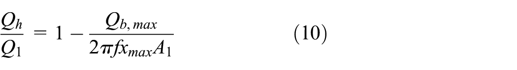
3.4.1. Flow rate ratio
Data processing procedures were developed to determine the flow rate ratio and performance parameters (inertance and equivalent damping coefficient) of the VIBFI at each data point. In this work, the flow rate ratio

where
where
3.4.2. Inertance
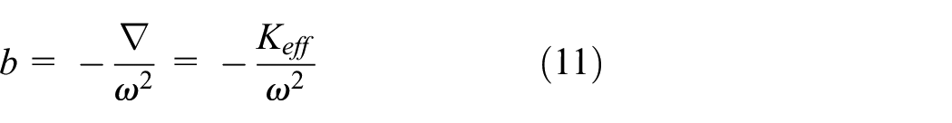
The inertance
To determine the bisector line for inertance calculation, one can compute the average value of terminal forces exerted by the inerter at the same terminal displacement level in its cycle across a range of terminal displacements. This range spans from the negative to the positive nominal amplitudes of the excitation. The linear equation of this bisector line is approximated using the Least Square method, which facilitates the determination of its gradient. Figure 8 illustrates an example of this bisector line, where the experimental data of the VIBFI under 5 mm sinusoidal excitation was used for illustration.
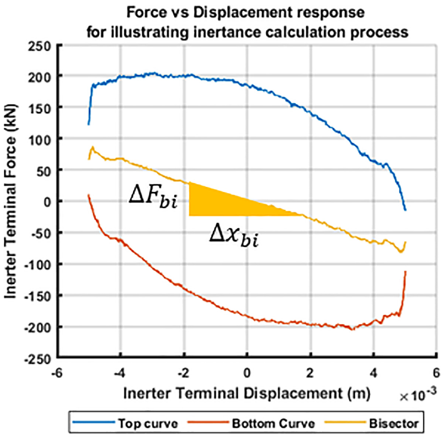
Force-displacement response graph with bisector line to illustrate the calculation process of inertance. The force values on the bisector line were calculated by taking the average of the force value on the top curve and bottom curve at the same terminal displacement level.
3.4.3. Damping coefficient
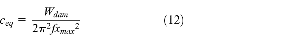
Under sinusoidal excitation, the equivalent damping coefficient
3.4.4. Mathematical model validation
The experimental and simulated performance parameters (inertance and equivalent damping coefficient) are compared to validate the mathematical models of the VIBFI. The percentage error approach was implemented for validation of the mathematical model from experimental results. The percentage error
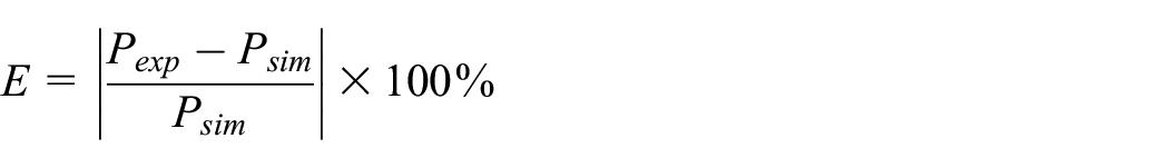
Subsequently, the average percentage error
4. Results
4.1. Experimental results
4.1.1. Controllability of
The relationship between valve knob position and flow rate ratio
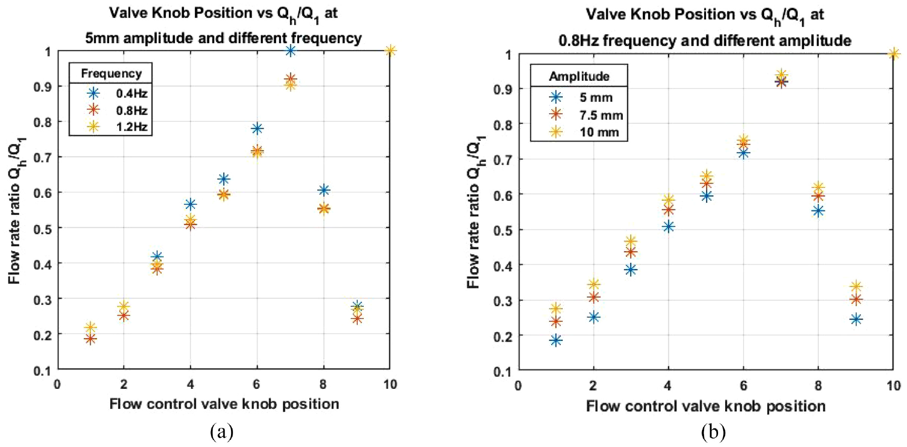
Plotting the flow rate ratio
4.1.2. Force-displacement response ellipses
Figure 10 plots the force-displacement response ellipses of the experimental prototype under a steady state sinusoidal excitation response of 5 mm amplitude and 0.8 Hz frequency. In the figure, each ellipse presents the force-displacement response of the VIBFI at a specific flow rate ratio
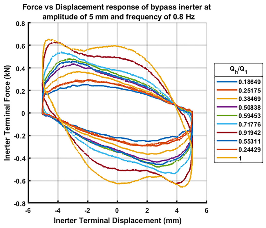
Force versus displacement response of the SBFI at different flow rate ratio
To examine how different excitation conditions impact the force-displacement response characteristic of the VIBFI, the responses under different excitation conditions were compared while keeping the valve knob position constant. In Figure 11(a), the force-displacement response ellipses of the VIBFI are plotted for different excitation frequencies at a fixed amplitude of 5 mm. Meanwhile, Figure 11(b) plots the response ellipses at the excitation frequency of 0.8 Hz with varying amplitudes.
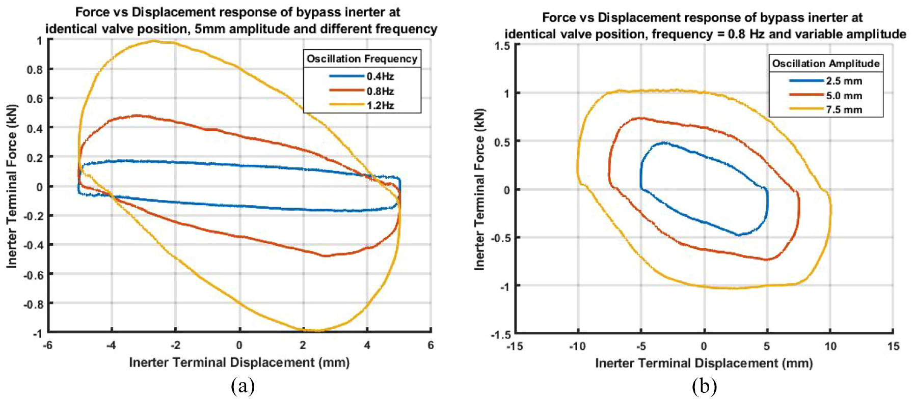
Force versus displacement response of the SBFI at identical flow rate ratio. (a) Depicts the response at different frequencies while (b) depicts the response at different amplitudes.
The observation from Figure 11(a) indicates that as the excitation frequency increases, there is a corresponding increase in the negative angle between the major axis of the response ellipse and the horizontal axis. Simultaneously, there is a rapid expansion in the area surrounded by the ellipse. Conversely, Figure 11(b) illustrates that increasing the sinusoidal excitation amplitude only results in a larger area bounded by the force-displacement response ellipses. These results suggests that while keeping the valve knob position constant, changing the sinusoidal excitation frequency affects both the negative stiffness and energy dissipation of the VIBFI. However, altering the excitation amplitude only affects energy dissipation of the device.
4.1.3. Inertance
The inertance of the VIBFI, as determined from experiments, was plotted against flow rate ratio
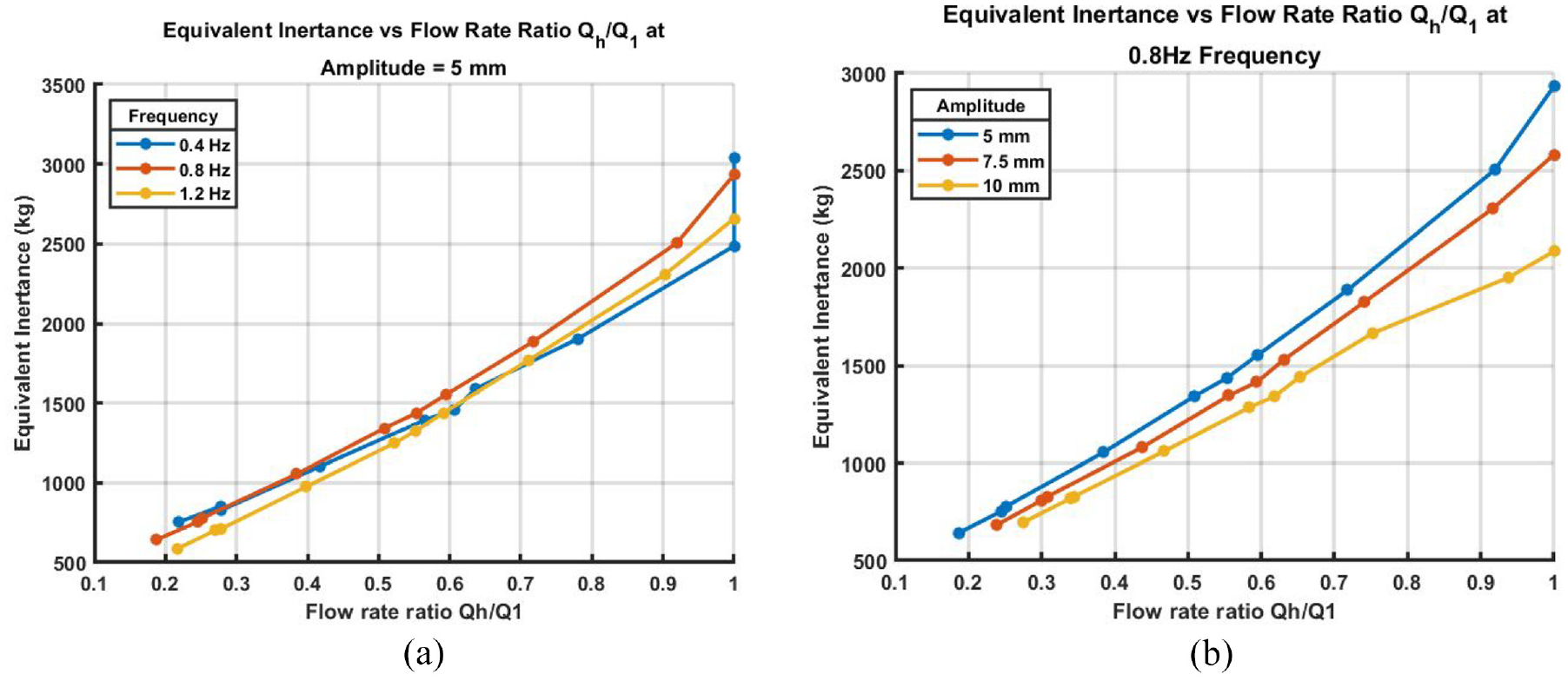
Relationship between inertance and flow rate ratio
4.1.4. Equivalent damping coefficient
The equivalent damping coefficient of the VIBFI was plotted against
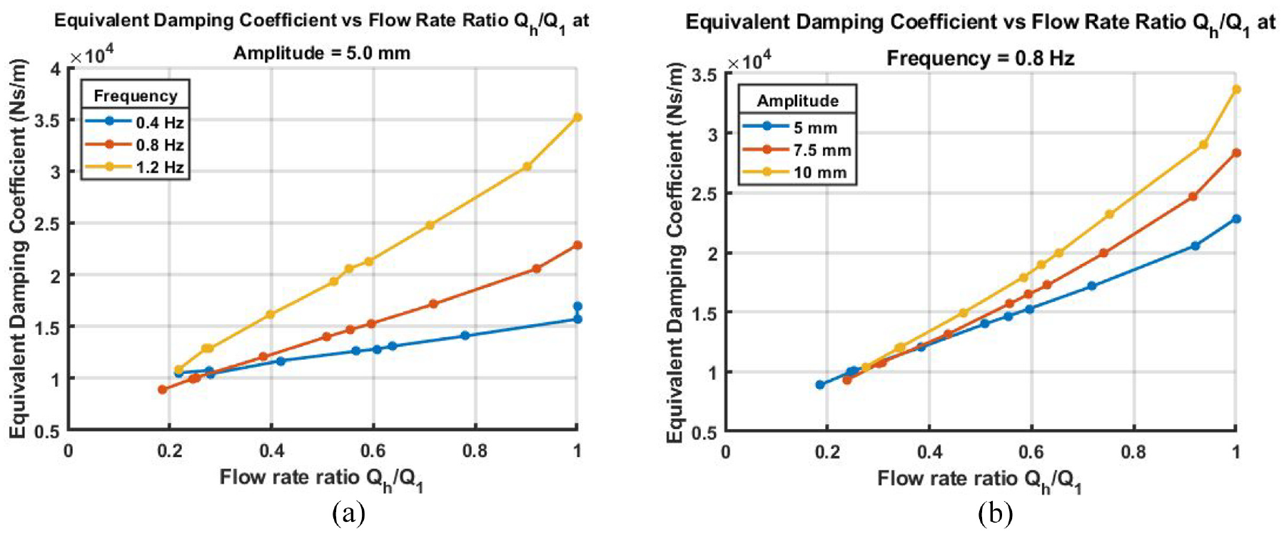
Relationship between the equivalent damping coefficient and flow rate ratio
4.2. Comparison between experimental and simulation results
The simulated and experimental results were compared against each other to validate the mathematical models of the VIBFI. Close alignment between experimental and simulated results would indicate validation of the device’s mathematical models. This subsection presents such comparisons regarding the force-displacement response ellipses, inertance and equivalent damping coefficient of the VIBFI.
4.2.1. Force-displacement response
The force-displacement response ellipses were plotted against each other at selected data points for comparison. These data points were chosen to represent the VIBFI’s response when the flow control valve is at its fully closed position (
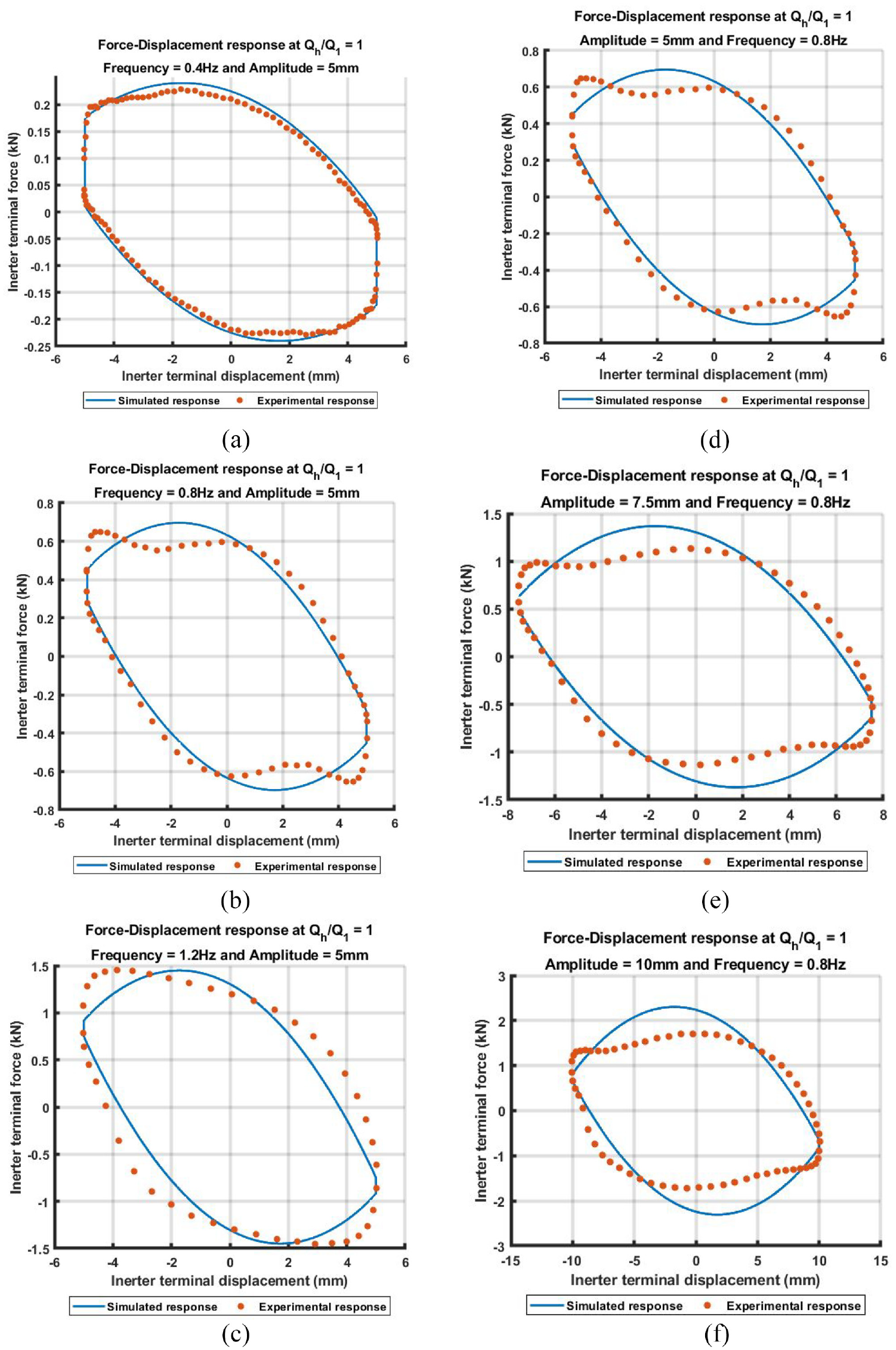
Comparison between the experimental and simulated force-displacement response ellipses of the inerter. Subfigure (a) to (c) depicts the comparison at the frequencies of 0.4, 0.8 and 1.2 Hz while the amplitude was kept constant at 5 mm; while subfigure (d) to (f) presents the comparison under excitation amplitudes of 5, 7.5 and 10 mm while the excitation frequency was kept at 0.8 Hz.
The simulated and experimentally determined force-displacement responses of the VIBFI fairly matches with each other. Perfect alignment was observed in Figure 14(c), where the excitation amplitude and frequency were set at 5 mm and 0.4 Hz respectively. Differences in negative stiffness between simulated and experimental response ellipses were noticeable, but subtle. There are noticeable differences between the areas bounded by the experimentally determined and the simulated response ellipses. Cavitations appear in the geometry of the experimentally determined force-displacement response ellipses. This effect is more pronounced when the amplitude or frequency is high.
4.2.2. Inertance
Figure 15 compares the experimentally determined relationship between inertance and flow rate ratio
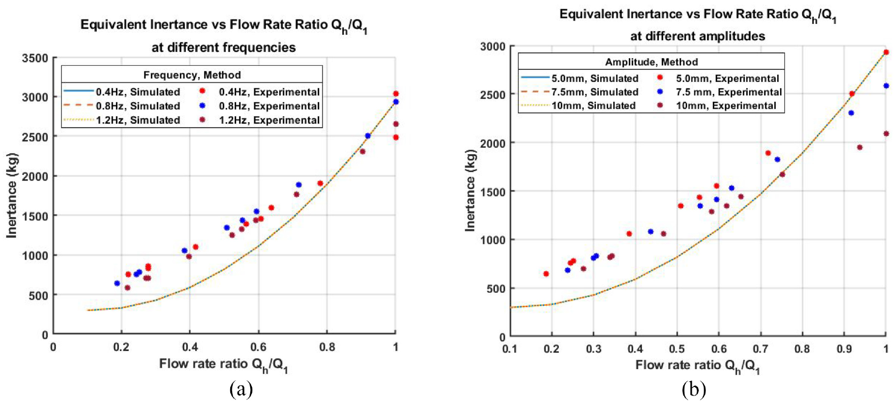
Comparison between experimental and simulated results: Equivalent inertance versus
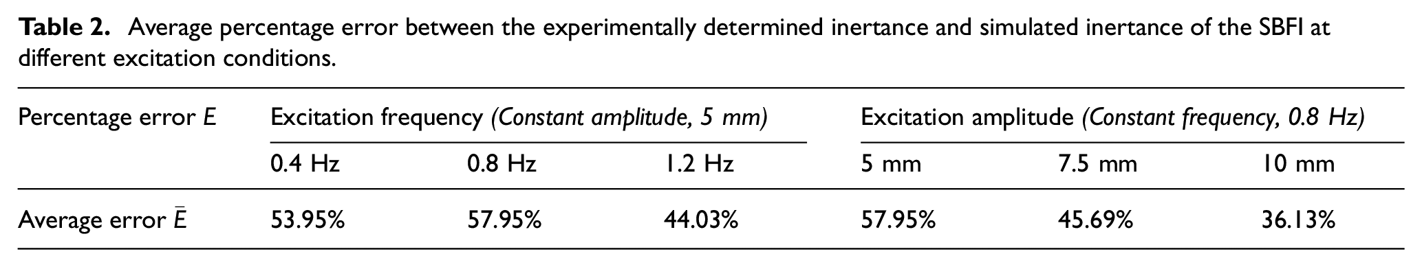
Table 2 displays the average percentage error
Average percentage error between the experimentally determined inertance and simulated inertance of the SBFI at different excitation conditions.
4.2.3. Equivalent damping coefficient
Figure 16 compares the experimentally determined equivalent damping coefficient against simulated results for all tested excitation conditions. Subfigure (a) to (c) depict the comparison under varied frequency and fixed amplitude, while subfigure (d) to (f) show the comparison under varied excitation amplitude with a fixed frequency. To some extent, the experimental data aligns with the simulated results. Discrepancy between experimentally determined and simulated damping coefficient are more noticeable at lower
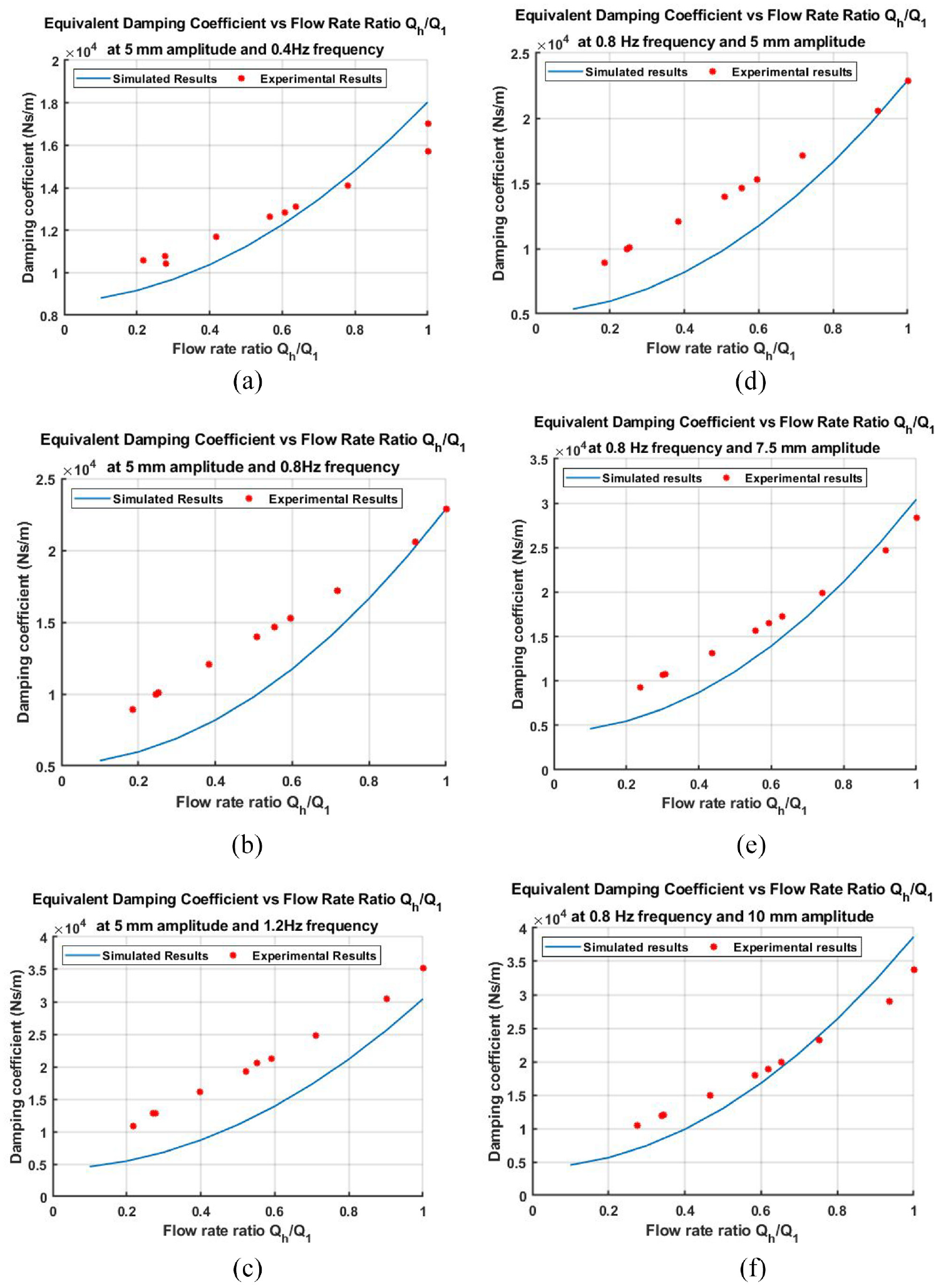
Comparison between experimental and simulated results: Equivalent damping coefficient versus Qh=Q1. Subfigure (a) to (c) depicts the comparison at the frequencies of 0.4, 0.8 and 1.2 Hz while the amplitude was kept constant at 5 mm; while subfigure (d) to (f) presents the comparison under excitation amplitudes of 5, 7.5 and 10 mm while the excitation frequency was kept at 0.8 Hz.
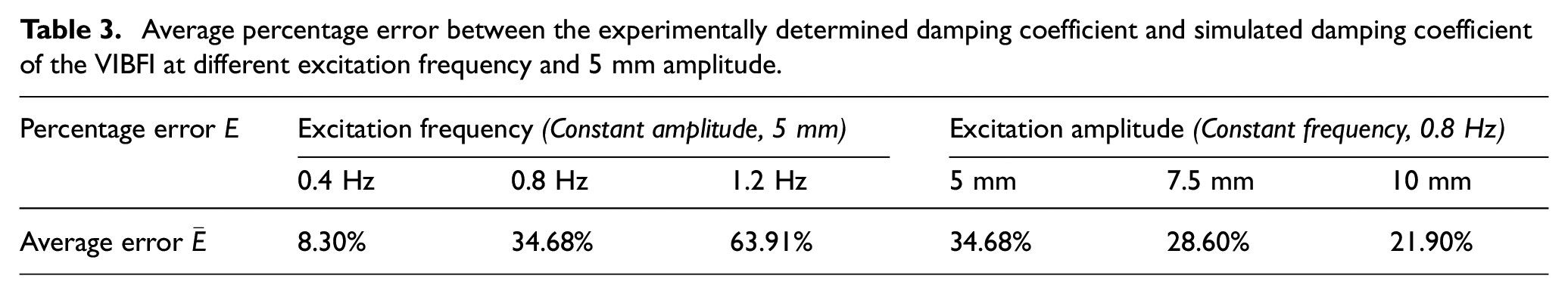
Table 3 presents the average percentage error
Average percentage error between the experimentally determined damping coefficient and simulated damping coefficient of the VIBFI at different excitation frequency and 5 mm amplitude.
5. Discussion
5.1. Controllability of inertance and damping coefficient
Experimental testing of the VIBFI under sinusoidal excitation was conducted to evaluate the device’s performance. Experimental results shown by Figure 9 revealed that adjusting the knob position of the flow control valve integrated into the bypass channel effectively controls the flow rate ratio
The experimental results implies that the VIBFI can provide controllable inertance as well as equivalent damping coefficient. These performance parameters (inertance and damping coefficient) can be continuously adjusted by modulating the flow restriction through the bypass channel, which is achieved by adjusting the opening of the integrated flow control valve. This underscores the feasibility of developing a semi-active inerter with variable inertance and damping coefficient by integrating a parallel bypass channel with a flow control valve into a fluid inerter. The large damping coefficient magnitude and controllability make the VIBFI effective as a device combining a variable inerter and damper. However, for applications that require purely variable inertance, minimising the damping effect of the VIBFI is essential.
5.2. Validation of mathematical model
Simulation results derived from evaluating the mathematical models of the VIBFI under similar independent variables and excitation conditions were compared against experimental results to validate the models. While the mathematical model can predict the real-world behaviour of the VIBFI in some scenario, there were still discrepancies between the model predictions and actual performance of the device. Typically, the model was able to accurately predict the VIBFI’s performance when the flow of fluid is entirely directed to the helical channel (when
Firstly, the mathematical model assumes that the internal diameter of the helical channel and the bypass channel remain constant throughout their lengths. These diameters significantly affect the device’s inertance and damping coefficient. While the diameter of the helical channel does remain constant, the bypass channel accommodates components such as fittings, valves and the flow sensor, which often have reduced internal diameter in their construction. This discrepancy explains why the mathematical model can accurately predict the performance parameters when there is no flow through the bypass channel (when
Secondly, the experimental prototype utilises a hall-effect type flow sensor that relies on the rotation of an impeller to measure fluid flow. Factors such as friction, efficiency, small misalignments in the assembly and the inertia of the impeller can affect the sensitivity and accuracy of the measurement. This discrepancy can lead to the measured flow rates through the bypass channel differing from the actual flow rates, affecting the measured value of
Thirdly, the vinyl tubing used for the helical and bypass channel, despite being reinforced with steel wire, remains flexible. Consequently, they can expand or contract due to changes in pressure while the terminals of the VIBFI are subjected to relative motion. This flexibility can lead to cavitations in the force-displacement response of the device and unwanted variations in the diameter of the fluid channels (helical and bypass), contributing to the discrepancies between experimental and simulation results. And lastly, despite efforts to minimise air bubbles in the system, there can still be air bubbles trapped in the working volume of the prototype. As air is compressible, this would affect the overall stiffness of the system, causing its actual performance to deviate from that estimated by the mathematical model.
6. Conclusion and future work
This technical paper documented the study of a semi-active inerter prototype dubbed the VIBFI. An experimental prototype of the concept was designed, constructed and tested. Simultaneously, an effort to develop and validate a mathematical model of the VIBFI is thoroughly detailed. The experimental results demonstrate the controllability of performance parameters of the device, including inertance and damping coefficients, through modulating the flow restriction of the bypass channel. The mathematical model derived for the VIBFI can predict its performance effectively when the flow through the bypass channel is blocked. However, there are still discrepancies between the experimental and simulated results. Future work will aim to address these discrepancies to produce a more reliable mathematical model, before integrating active control systems into the device and performing design optimisation.
Future work should focus on improving the prototype of the VIBFI and the mathematical models to achieve better alignment between experimental and simulated results. Improvements in the construction of the prototype are necessary to enhance the agreement of its performance with its mathematical models. Firstly, improvements can be made to the prototype by using more rigid tubing, such as copper or stainless steel, to fabricate the helical channel and the bypass channel. This improvement is expected to reduce the cavitations in the force-displacement response and the unwanted variations in the fluid channel’s diameter, thereby improving the alignment between simulated and experimental data. Secondly, increasing the length of the bypass channel can reduce the effect of inner diameter reductions caused by components installed on it such as flow sensors, valves or fittings. This adjustment ensures that the average inner diameter of the channel closely matches that of the tubing used for the channel. Thirdly, the prototype can also be enhanced by implementing more accurate flow sensors for measuring the flow rate through the bypass channel. The mathematical model also requires refinement to address discrepancies between the simulated and experimental data. Further research is recommended on the dry friction component of the VIBFI, particularly regarding its behaviour under varying excitation conditions. Additionally, the effect of air bubbles trapped in the fluid system on the performance of the VIBFI can be integrated into the mathematical model.
Once the mathematical model and the designs are refined, an active control system can then be integrated to modulate the inertance of the VIBFI. A possible control strategy for the inertance of the VIBFI is as follows: The control system will include an automatic flow control valve where its opening can be controlled based on the desired inertance input and data from the flow sensor as well as the motion of the terminals to achieve the desirable inertance. Measured flow rate from the flow sensor and velocity data of the VIBFI’s terminals can be used to evaluate the current
The improved mathematical model can be employed to optimise the performance of the VIBFI. Utilising the equations to describe inertance and damping coefficients as objective functions, multiple-objective optimisation methods can be implemented to determine the design dimensions of the VIBFI according to the desired design requirements. For instance, the optimisation method can be used to derive the design dimensions of the VIBFI to maximise inertance while minimising damping as needed. In addition, if the mathematical model of the VIBFI can accurately represent its actual performance, it can be implemented into simulations of semi-active mechanical systems that incorporate the device to provide more realistic results.
Footnotes
Acknowledgements
The authors acknowledged the use of OpenAI ChatGPT in order to improve the language during the writing process.
Declaration of conflicting interests
The author(s) declared no potential conflicts of interest with respect to the research, authorship, and/or publication of this article.
Funding
The author(s) disclosed receipt of the following financial support for the research, authorship, and/or publication of this article: The authors acknowledge the financial support provided by the Australian Government Research Training Program (AGRTP) scholarship and Australian Research Council (ARC) Linkage Grant under grant number LP210301054.