
Abstract
Magnetically levitated permanent magnet planar motor is a new-generation motion device in modern precision industry, and the design of advanced motion controller has always been a main concern in the research and development of magnetically levitated permanent magnet planar motor. Due to the decrease in electromagnetic force caused by the deflection of the mover or the sharp decrease in magnetic flux density with height, it is very difficult to realize accurate positioning control of 3 degrees of freedom. In this article, an active disturbance rejection control scheme is adopted. The extended state observer is used to estimate the comprehensive disturbance and motion state in real time. Then, according to the value estimated by the extended state observer, the active disturbance rejection control motion controller can compensate the electromagnetic force in time to achieve good anti-jamming performance. Simulation and experimental results demonstrate that the adopted active disturbance rejection control scheme has good dynamic performance and uncertain disturbance robustness.
Keywords
Introduction
The permanent magnet planar (PMP) motor has become one of the best performing mechanisms of the new-generation lithography machine due to its structural diversity, larger thrust density, favorable low-speed stability, and other excellent properties. 1 Traditional two-dimensional (2D) plane positioning device is generally composed of two sets of linear motion conversion structures and driven by two rotating electric motors. However, it is difficult to achieve higher level positioning accuracy owing to the linear motion conversion mechanism of friction, backlash, and deformation. Although air bearing positioning platform can eliminate the friction, its structure is complex and the support stiffness is small, which result in lower bearing capacity and poor ability to resist shock. Furthermore, air bearing positioning platform fails to meet the requirements of ultra-precision machining of the next generation.2,3 In recent years, several types of magnetically levitated permanent magnet planar (MLPMP) motors have been proposed. Those planar motors, which can realize large-range planar motion in high vacuum with simple structure, high speed, and high precision, have drawn more and more attention in the academic field.
MLPMP motor is a multi-input multi-output, nonlinear, strong coupling, and complex system with multiple degrees of freedom. The realization of high-precision positioning and 6-degree-of-freedom (6-DOF) motion largely depends on the planar motor structure and the control system design.4,5 In Rovers et al., 6 a new analytical tool is proposed, by looking up table data, to calculate the thrust and torque quickly and accurately, which can improve the positioning accuracy of the planar motor. In Peng et al., 7 the corner segments of the coil are taken into account, and a real-time control model, derived using the theory of composite numerical integration and the Newton–Leibniz formula, is proposed to improve the control accuracy of the magnetically levitated ironless planar motor. However, in actual operation of the motor, the mover will have a small angle deflection that may change the model of the motor. If the control algorithm relied too much on accurate model, the control accuracy would be declined. Besides, the thrust and levitation forces of the PMP motor are difficult to be directly fed back with the sensor, which makes it difficult to achieve a precise control. In Ruderman et al., 8 the dual closed-loop control of the loop, taking into account the nonlinear relationship between the motor and the load, improves the positioning accuracy of the load using the Luenberger state observer to feedback the velocity of the motor. In Ruderman and Iwasaki, 9 a sensorless control of the motor velocity based on an extended state observer (ESO) is proposed and used in a two-mass actuator system. The designed and evaluated observer provides a robust feedback control over a large-varying operation range. This state observer can be space- and cost-saving and has great significance to the industrialization of magnetic levitation technology.
The active disturbance rejection control (ADRC) is a new nonlinear algorithm for motor control in recent years. It has been demonstrated that the combination of nonlinear control strategy and real-time estimation of comprehensive disturbance can get a good control effect.10,11 The standard ADRC is independent of the specific mathematical model of the controlled object and only needs to be designed according to the order of the controlled object. Currently, the method of ADRC has been successfully applied in unmanned aerial vehicle (UAV) and induction motor,12,13 but it is rarely used to control MLPMP motor.
In this article, on the basis of reasonable hypothesis, the electromagnetic force of the mover is analyzed when small deflection occurs. Force change caused by parameter variations is viewed as the internal disturbance of the system, and abrupt load is the external disturbance. ESO is applied to estimate the motion state and the comprehensive disturbance of internal and external disturbances. ADRC is adopted to realize x-axis (and y-axis) horizontal positioning and z-axis vertical positioning of the mover. The simulation and experimental results illustrate that the ADRC controller can effectively improve the positioning accuracy and robustness of uncertain disturbance.
MLPMP motor and current distribution in the coils
Configuration of MLPMP motor
The MLPMP motor is constituted by one stator and one mover. The stator consists of a 2D Halbach permanent magnet array and the mover consists of ironless coil array.14–16 The square magnet is the main magnet, and its magnetization direction is perpendicular to the surface of the magnet array. The rectangular magnet is the secondary magnet, and its magnetization direction is parallel to the surface of the magnet array. The thickness of the two kinds of magnets is equal, and they are uniformly magnetized with the same magnetization intensity. This arrangement makes the magnetic flux density of one side very strong while that of the other is very weak. Coils are located on the side of the strong magnetic flux density. Figure 1 illustrates the configuration of the MLPMP motor. The side length of the main magnet is

Top view and side view of the investigated MLPMP motor.
Current distribution in the coils
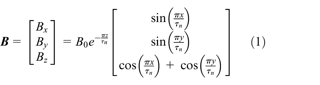
As shown in Figure 1, a coordinate system xyz is defined in the Euclidian space to model the planar motor, and the origin is defined in the center point of N pole magnet surface. Neglecting all higher-order harmonics and the edge effect of magnetic field (i.e. assuming the magnetic field has infinitely large area), the analytical model of the first-order harmonic magnetic flux density distribution in fixed coordinate system xyz can be represented as follows 17
where
According to Lorentz force law, when the current-carrying coils are located on the magnetic field, the interaction between the coils and the magnetic field, that is, the Lorentz force and torque, is generated and can be calculated.
18,19
In Zhang et al.,
20
the model of electromagnetic forces–torques is given; meanwhile, a current control method is proposed for the 6-DOF MLPMP motor to realize synchronous decoupling of the force and torque. In the coordinate system, the mass center point of moving-coils array is defined and expressed with
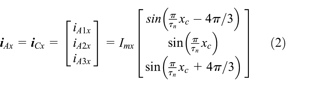
The current distributions of group A and group C, respectively, which only generate x-axial thrust, are as follows

where
The current distributions of group A and group C, which only generate z-axial thrust, are as follows


where
Similarly, adopting proper current distributions like those of group A and group C, group B and group D can generate only y-axial thrust or z-axial thrust.
Electromagnetic force analysis for deflected mover
Finite element simulation of the MLPMP motor is carried out with Ansoft Maxwell 3D. The finite element simulation model of the motor is shown in Figure 2. The model material of permanent magnet is NdFe35. The polar distances τn is 17.68 mm, the permanent magnet thickness hm is 10 mm, the air gap height is 1 mm, the coil thickness is 7.4 mm, and other dimensions of the coil are shown in Figure 1. The number of turns of the coil is 165. The coils are energized according to equations (2) and (4). Since cooling conditions limit the value of the coil current, a current amplitude of 3 A is adopted to investigate the variations of thrust and levitation force.

Simulation model of the MLPMP motor.
Figure 3 shows the variation of levitation force when the mover rotates around the z-axis, where θ is the rotation angle around the z-axis. From Figure 3(a), it can be concluded that (1) when θ = 0°, the z-axial levitation force is the maximum; (2) the levitation force nonlinearly decreases with the increase in θ; (3) when θ = 10°, the levitation force decreases to a quarter of the maximum; and (4)
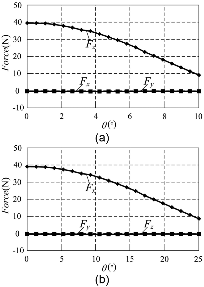
Relationship between electromagnetic force and θ: (a) relationship between z-axial levitation force and θ and (b) relationship between x-axial thrust and θ.
From the above simulation results, the fitting equation of Fz can be expressed as follows

where A is scale factor. Similarly, the equation of Fx and Fy can be expressed as follows
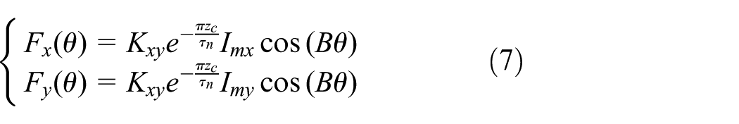
where B is scale factor.
Design of ADRC controller
The controller of horizontal direction
For the MLPMP motor, if the uncertain disturbance caused by the mover deflecting through small angles is considered, and based on equations (3) and (7), the mechanical thrust balance equation describing the x-axial horizontal motion can be expressed as follows

where

From equation (9), it can be observed that the differential equation contains a comprehensive disturbance

where
The control system of the x-axial motion for MLPMP motor is shown in Figure 4, where

Block diagram of ADRC controller in horizontal x-direction.
TD can be given as follows

where
NLSF can be given as follows


where
ESO can be given as follows21,22
where
The controller of vertical direction
If the uncertain disturbance caused by the mover deflecting through small angles is considered, based on equations (5) and (6), the mechanical thrust balance equation describing the z-axial vertical motion can be described as follows

where

Combining the ADRC and the sharp decrease in magnetic flux density with height, equation (17) can be replaced by

From equation (18), it can be observed that the differential equation contains a comprehensive disturbance

where
The control system of the z-axial motion for MLPMP motor is shown in Figure 5, where

Block diagram of ADRC controller in vertical z-direction.
ESO can be given as follows21,22

Figure 6 shows the structure of 3-DOF positioning system for MLPMP motor.

Structure of 3-DOF positioning system for MLPMP motor.
Results and analysis of simulation
The parameters of simulation
In order to verify the effectiveness of ADRC, an ADRC system for MLPMP motor is built and simulated in the MATLAB/Simulink environment. There are so many parameters of ADRC to set. First, the observer gains
Parameters of ADRC control system.

ADRC: active disturbance rejection control.
In the simulation of horizontal direction,
The simulation of horizontal motion
For the MLPMP motor control system in horizontal x-direction, the external disturbance usually comes from the load change, while the internal disturbance from the small angle deflection of the mover. To verify the control performance of ADRC, a step signal of 10-mm horizontal motion is given at 0.5 s, an unknown system disturbances of 0.5 sin(20t)N and an abrupt horizontal load of 19.6 N are applied at 2.5 s, and the mover counterclockwise deflects about 5°. When the abrupt horizontal load is applied, the increase in mass is 2 kg.
Figure 7(a) shows the step response of ADRC in the horizontal x-direction. As can be seen, the rise time of the 10-mm step response is about 0.125 s, and the overshoot and the static error are almost 0. When the disturbances are applied at 2.5 s, the adjusting time is about 0.185 s. In order to compare the control performance, the step response of PID is shown in Figure 7(b). In the case of step response, the adjusting time is about 0.3 s, and overshoot is 19.2%. When the same disturbances are applied at 2.5 s, the adjusting time is about 0.25 s. Table 2 presents a list of control performances between the PID controller and the ADRC controller. This shows that the system controlled by ADRC has achieved a faster step response without overshoot and better anti-jamming performance.

Simulation results in the horizontal x-direction: (a) the displacement response of ADRC, (b) the displacement response of PID, (c) the Imx response of ADRC in the step response case, (d) the Imx response of ADRC under abrupt load, and (e) the disturbance estimation of ADRC.
Control performance list of horizontal motion between the PID and the ADRC.

PID: proportional–integral–derivative; ADRC: active disturbance rejection control.
The response of
The simulation of vertical motion
To verify the control performance of ADRC in the vertical direction, the mover counterclockwise deflects about 5°, and a step signal of 1-mm vertical motion is applied at 0.5 s. An unknown system disturbances of 0.5 sin(20t)N and an abrupt vertical load of 9.8 N are applied at 2.5 s. When the abrupt vertical load is applied, the increase in mass is 1 kg.
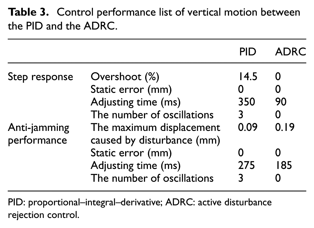
The response of the z-axial vertical motion is shown in Figure 8(a). The rise time of the 1-mm step response is about 0.09 s, and the overshoot and the static error are 0. When an abrupt vertical load of 9.8 N is applied at 2.5 s, the adjusting time is about 0.185 s. Figure 8(b) shows the response of PID in the same simulation conditions. In the case of step response, the adjusting time is about 0.35 s and overshoot is 14.5%. When the same disturbances are applied at 2.5 s, the adjusting time is about 0.275 s. Table 3 presents a list of control performances between the PID controller and the ADRC controller. In the process of levitation, the magnetic flux density constantly decreases with height and the parameter of control object constantly changes. Compared with the response in the horizontal x-direction, there are stronger oscillations and longer adjusting time in the PID scheme. While for ADRC, since the disturbance can be estimated by ESO and rapidly compensated, the control effect is unchanged. The simulation result indicates that the disturbance can be overcome effectively and the ADRC have satisfactory adaptation ability.
When the mover is deflected about
Control performance list of vertical motion between the PID and the ADRC.
PID: proportional–integral–derivative; ADRC: active disturbance rejection control.
When the mover is deflected about
Results and analysis of experiment
Experimental platform of MLPMP motor
In order to verify the theoretical analysis results and confirm the feasibility of the electromagnetic suspension, a prototype is made and an experimental platform of the magnetic levitation system is set up as shown in Figure 9. The length of the mover is about 245 mm and that of the stator is about 450 mm. The displacement in horizontal direction is measured by a position sensor installed on one side of the stator, and four position sensors are fixed on the top of the mover to get real-time vertical displacement. These position sensors are all laser sensors with a resolution of 2 µm and a measurement accuracy of 6 µm. Four universal ball bearings are mounted on the surface of the mover and the double guide rails are installed on both sides of the mover. Adjusting the distance between the ball bearing and the guide rail can make the mover deflect. The hardware of controller is composed of industrial computer, peripheral component interconnection (PCI) data acquisition cards (DAQ), and current converter. The computer is used to implement the control algorithms. The PCI DAQ cards, which consist of an AD PCI-1716 card and a DA PCI-1724 card, are used for data acquisition and signal transformation. The current converter, which is a unit of analog circuit of current loop, is used to realize amplification and filtering of current signal. The controller executes algorithms at a sampling frequency 5 kHz.
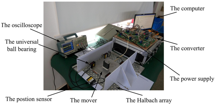
Experimental platform of MLPMP motor.
The experiment of horizontal motion
The step response of 10-mm horizontal motion is shown in Figure 10(a). The current waveforms of group A are shown in Figure 10(b). Next, an abrupt horizontal load of 19.6 N is applied, and the mover is deflected 5°. The response of horizontal motion is shown in Figure 11(a), and current waveforms of group A are shown in Figure 11(b). Table 4 presents a list of key performances of horizontal motion between the simulation and the experiment. The experimental results are in close agreement with the simulation results and the aforementioned analysis. This means ADRC is influenced slightly by external disturbances and has strong robustness. Nevertheless, compared with the simulation results, due to sample rate limiting of position sensors, the adjusting time is longer and the maximum displacement in the horizontal x-direction is larger.

Experimental results of step response in the horizontal x-direction: (a) the step response of displacement and (b) the current waveforms of group A.

Responses under abrupt load in the horizontal x-direction: (a) the response of displacement in horizontal x-direction and (b) the current waveforms of group A.
Control performance list of horizontal motion between the simulation and the experiment.

The experiment of vertical direction
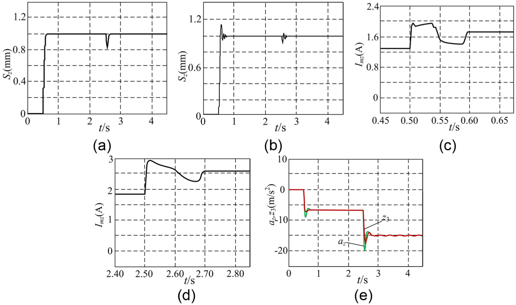
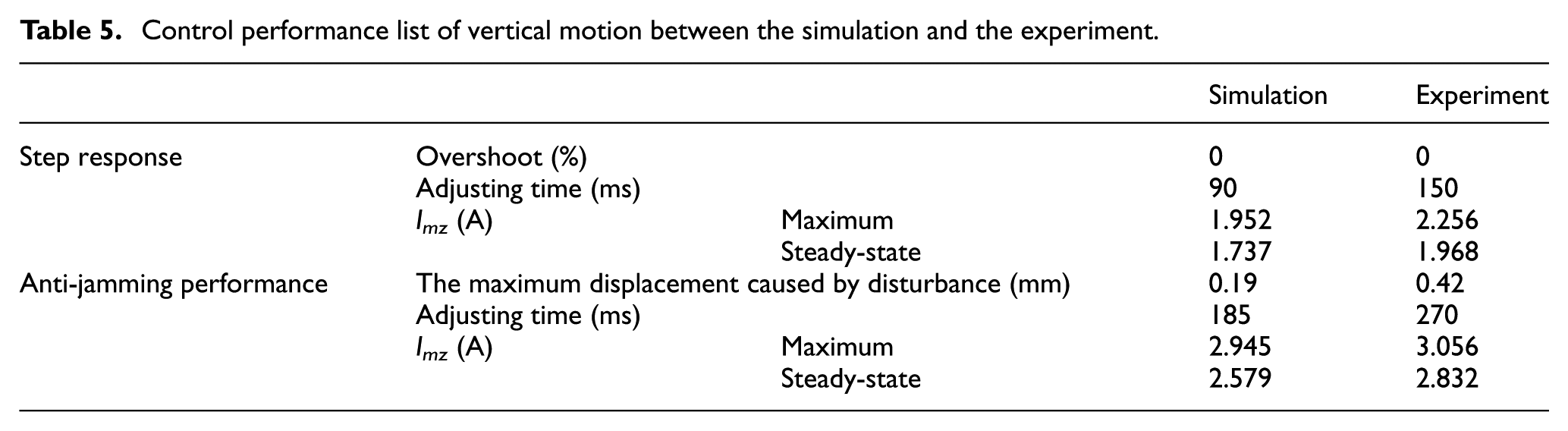
The mover is deflected about 5°. Figure 12(a) shows the 1-mm step response of displacement in the vertical z-direction. Figure 12(b) shows the current waveforms of group A. Next, an abrupt vertical load of 9.8 N is applied. The response of vertical motion is shown in Figure 13(a), and current waveforms of group A are shown in Figure 13(b). Table 5 presents a list of key performances of vertical motion between the simulation and the experiment. The experimental results and the simulation results are in close agreement. Also, similar conclusions can be drawn from the experimental results.

When the mover is deflected about 5°, experimental results of step response in the vertical z-direction: (a) the displacement response and (b) the current waveforms of group A.

When the mover is deflected about 5°, experimental results under abrupt load in the vertical z-direction: (a) the response of displacement and (b) the current waveforms of group A.
Control performance list of vertical motion between the simulation and the experiment.
Conclusion
In this article, the ADRC scheme is adopted to estimate the comprehensive disturbance including the internal and external disturbances, and a 3-DOF ADRC controller for MLPMP motor is designed to realize x- and y-axial horizontal positioning and z-axial vertical positioning. When the deflection of moving-coils occurs or the magnetic flux density varies during suspension, the disturbances can be estimated in real time so that the electromagnetic force can be compensated in time. Simulation and experimental results show that the 3-DOF ADRC controller has fast response, no overshoot, high accuracy, and strong robustness against parameter variations and load disturbance. In addition, the 3-DOF ADRC controller can be designed independently and the control strategy can be applied to engineering easily. In our next study, further efforts will be made on how to realize 6-DOF control of MLPMP motor.
Footnotes
Academic Editor: Yongping Pan
Declaration of conflicting interests
The author(s) declared no potential conflicts of interest with respect to the research, authorship, and/or publication of this article.
Funding
The author(s) disclosed receipt of the following financial support for the research, authorship, and/or publication of this article: This work was supported by the National Natural Science Foundation of China (nos 51377074, 51475214, and 51305170), the China Postdoctoral Science Foundation Funded Projects (nos 2015T80508 and 2016M601726), the Six Categories Talent Peak of Jiangsu Province under Projects (nos 2015-XNYQC-003 and 2014-ZBZZ-017), and the Priority Academic Program Development of Jiangsu Higher Education Institutions.