
Abstract
This article aims to present a new type of friction stir weld spindle system with 2 degrees of freedom. It explains the thermal–mechanical coupling mechanism between the welding tool and the workpiece, presents simulation of the heat distribution on a friction stir weld spindle under specific welding technology parameters, and provides the type selection and the reference design for temperature-sensitive components such as bearings and motor. The spindle system, which has high stiffness and excellent resistance to overload, is developed in accordance with the welding requirement for aluminum alloy products in the aeronautic and astronautic fields. The thermal–mechanical coupling model is established between the stir-pin and the workpiece. The heat generation and transfer processes are simulated, and the results of the temperature field distribution for the target position inside the spindle structure are obtained and verified by experiments. Test results show that the spindle system can meet the requirements of friction stir welding for large-scale complex surface structures. Simulation analysis has good consistency with experimental results, as proved by experimental verification. The resulting data can provide reliable reference design and type selection of temperature-sensitive components. Compared with other stir welding heads, this system has high stiffness and overload capacity, which can well meet the high-quality welding requirements of large-scale complex surface structures. Besides that, the thermal analytical method has universal applicability and can provide solutions for temperature field distribution of spindle under different workpiece materials and welding parameters. The friction stir weld spindle system is a novel design for welding large-scale complex surface structures. Its major advantages are the high stiffness and overload capacity. In addition, the heat and thermal simulation method, consisting of two stages, has provided the type-selection reference for the spindle design.
Introduction
Friction stir welding (FSW) is a solid-state joining process that presents many advantages compared to traditional fusion welding due to its attractive joint mechanical properties and environmental friendliness. In addition, neither welding wire nor welding pretreatment is required. 1 Therefore, FSW has widely been adopted in various industries worldwide.
The welding head or the spindle system is the key to FSW technology as well as the core of this welding method. In the inserting stage, the ultimate contact between the welding head and the workpiece occurs in the plastic stage. To soften materials to plunge into the workpiece, the welding head will rotate at a high speed and withstand enormous pressure and friction torque. To ensure normal geometric accuracy, the downforce on the welding head must be guaranteed and controlled effectively. In the stage of welding, there is a great feeding resistance and a transverse disturbance force acting on the welding head. Compared to traditional cutting load or drilling load, the working conditions of FSW are more complex and strict. 2
Many aerospace parts of large size and complex structure must be spliced or connected by aluminum (Al) alloy sheets using a welding process, such as the tanks in heavy launch vehicle, large aircraft skin, and fighter intake duct. 3 To guarantee the welding quality, it is necessary to control the relevant welding process parameters strictly, such as the spindle’s rotation speed, insert speed, insert depth, transverse welding speed, and welding pressure. These parameters directly determine how much heat is generated from the welding process. They can cause poor-quality weld seam if they are too high or too low. Therefore, appropriate heat generation is the most important condition to obtain high-performance welding joints. 4 However, due to the fact that aerospace components have different sizes, thicknesses, geometric configuration, and material properties, these parameters must be reasonably selected and controlled to obtain a satisfactory welding effect. Therefore, the design of the FSW spindle system is particularly important as it can not only satisfy basic mechanism function (telescoping and rotation) but also meet the indexes and functional requirements of specific welding technology parameters. Moreover, the structural design of the FSW spindle should consider sufficient high stiffness and strength to improve the joint’s geometric accuracy (straightness and planeness, etc.) and to avoid structural failure due to loads of high intensity, resulting from the welding process. Regarding the development of FSW tools or spindle system, N Mendes et al. 5 developed a novel FSW robotic platform and spindle system, which is more flexible, cheaper, easier, and faster to weld irregular surface. Li and Liu 6 designed a type of nonrotational shoulder–assisted (NRSA) FSW tool to weld high-strength aluminum alloy 2219-T6. The authors show that the maximum tensile strength obtained can reach 69.0% of the base material (BM). Shi et al. 7 used a 3-PRS (P, R, and S standing for prismatic, revolute, and spherical joint, respectively) parallel mechanism as the FSW tool. The structure design is not only compact and dexterous but also has good stiffness. Eslami et al. 8 summarized the structural composition of different types of FSW tools and analyzed their weld strength and the most effective welding parameters for different polymeric materials.
Because FSW is a strongly nonlinear thermal–mechanical coupling process, the heat mainly comes from the friction between the stir-pin and the workpiece, and the materials’ plastic deformation.9,10 To accurately obtain optimal heat production and appropriate welding technology parameters for a variety of workpieces, the numerical simulation technology is the most effective and fastest method. It can not only obtain the structure’s temperature distribution and the joint’s mechanical properties at a low cost but can also verify the influence of the welding technology parameters on the welding performance. 11 Schmidt et al. 12 considered the heat produced from the welding interface between the stir-pin and the workpiece, and the stir-pin geometric characteristics and contact forces between them. Based on those considerations, the heat-generated equation was deduced. Chen et al. 13 accomplished the full coupling solution of the FSW process considering heat production, temperature, and plastic flow fields and studied the heat spatial distribution around the stir-pin. Su et al. 14 thought that the viscosity coefficient and sliding that occur between the interfaces were the keys to control the heat production and distribution and studied sliding, adhesive states, and the heat production situation. Cho et al. 15 established a three-dimensional (3D) computational fluid dynamics model and induced plastic deformation into the workpiece.
From the results of numerical simulation analyses, on one hand, we can obtain the temperature field, which is particularly important to evaluate the welding effect and to improve the welding technology parameters. On the other hand, we can also obtain the wall temperature of shoulder on stir-pin, which is the original input condition for the spindle thermal analysis. The FSW spindle is the power source of welding and of welding heat transfer through internal structure connection. Depending on different working conditions and welding time, the generation of heat and temperature distribution on the spindle is not always identical. According to the quantity of heat production and different distribution locations, the welding performance of the spindle will be affected by different degrees. Therefore, active thermal control and external cooling measures should be taken whenever necessary. Therefore, the heat transfer and the thermal analysis of the FSW process are particularly important for the design of the FSW spindle, which is the type-selection and design reference for temperature-sensitive components, such as spindle bearings and motor. Regarding heat transfer and thermal analysis for spindle systems, Fehrenbacher et al. 16 embedded two thermocouples into the FSW tool’s holes and measured the shoulder and pin interface temperatures. By changing the process parameters (namely, thermal conditions), the weld quality can be maintained. Zivkovic et al. 17 established a thermo-mechanical model of a high-speed spindle with angular contact ball bearings. The increase in the range of bearing temperature caused by the spindle speed is relatively remarkable. The simulation results are in good agreement with the data obtained from a series of experimental curves with errors less than 5%. Ma et al. 18 proposed a type of transient thermal–structure interactive analysis method for a high-speed spindle, which can effectively avoid the sudden failure of high-speed spindles in the actual machining process caused by an excessive increase in the temperature at the design stage. The results showed that the finite element analysis model was much more accurate than the traditional model.
This article proposes a new type of FSW spindle for large-scale complex surface structures. It also establishes the thermal–mechanical coupling model between the stir-pin and the workpiece and obtains the temperature field distribution results for the spindle and the workpiece. The following sections of this work are organized as follows. Section “The FSW spindle system” introduces the FSW spindle used in this study; the thermal–mechanical coupling model and numerical simulation are established in section “Friction stir weld thermal–mechanical coupling simulation;” section “FSW spindle heat transfer analysis” describes the heat transfer analysis; the verification experiment is given in section “Welding experiment results;” and conclusions are drawn in section “Conclusion.”
The FSW spindle system
The design technology of the stirring head is one of the most important technologies in the FSW process. A good stirring head is beneficial for expanding the types of materials to be welded and for increasing sheet thickness. The improvement and optimization of this technology prolong the life of the stirring head and improve the product’s quality, which can result in huge economic and social benefits. Because of low stiffness, poor load resistance, and low temperature sensitivity, the classical stirring head-spindle system is applied to welding process of 6XXX aluminum alloy. For high-strength materials, such as 2XXX and 7XXX aluminum alloys, it is important that the stirring head-spindle system has sufficient strength and stiffness to ensure the geometry precision of the weld seam. In addition, the spindle speed is closely related to the mechanical properties of the stirring head. Compared with the traditional stirring head, the design index of spindle speed for the new stirring system is set to ≥1000 r/min, which is necessary for high-quality welding of workpieces with different materials and different thicknesses.
The main function of the FSW spindle is to perform a 2-degree-of-freedom (DOF) movement, comprising telescoping and rotation. These two movements are independent of each other and uncoupled. This is mainly because the function of each one of the 2 DOF is not the same. The telescopic DOF is mainly responsible for the control of the insert depth and the force, and the rotation DOF is responsible for increasing or decreasing the revolving speed so as to soften the materials. Due to the fact that the welding process requires a slow feed speed and a high revolving speed, these 2 DOFs must be designed separately. The transmission principle of the FSW spindle is shown in Figure 1.

Transmission mechanism principle of the FSW spindle.
The telescopic movement is designed through three feed motors to drive three planetary gears (gears 1–3), and these three small gears drive a sun gear simultaneously. However, the big sun gear can transmit torque by connecting to the screw nut. Therefore, this DOF is mainly dependent on screw driving. The rotation movement is implemented by a rotation motor directly connected to the main driving shaft. Therefore, the resistance torque is directly dependent on the spindle drive motor. Moreover, eight angular contact ball bearings are divided into two groups (front bearings and back bearings) installed back-to-back on each end of the main driving shaft, respectively, which are used to improve the spindle’s radial stiffness.
The structure design of the FSW spindle system is shown in Figure 2. The motion parts mainly comprise one rotation motor for rotary motion, three feed motors with reducers for axial motion, three gear pairs composed of three planetary gears, a sun gear, a screw pair composed by a screw nut, a screw rod, and a main driving shaft. Besides, two types of bearings are adopted in the structural design of the transmission mechanism. They are the double-row cylindrical roller bearing and the thrust ball bearing. They can significantly enhance the spindle stiffness and strength. The stationary parts are mainly made up of a spindle box for structural support, an end cover, and a seal cover. Moreover, it should be emphasized that a heat insulation layer with low thermal conductivity is added between the rotation shaft and the welding tool, which could reduce the heat conduction rate and increase the thermal equilibrium time of the spindle. The structural design of the spindle system is exquisite and compact. However, at the same time, it has the characteristics of heavy-load resistance and high stiffness.

Structure design of the FSW spindle system.
In the early experiment, the FSW process for AL2024 plates of 9.5 mm thickness was studied. The welding tool in which the pin has a diameter of 11.1 mm, length of 8.9 mm, and a shoulder with an outside diameter of 25.4 mm is used for the process test. The longitudinal feed rate along the welding joint is 90 mm/min and the spindle speed is 700 r/min. According to the above results from the process test, and considering a certain safety allowance, the maximum load design of the welding head is specified in Table 1. Based on the load input and, at the same time, considering the welding requirements of aerospace components composed by large-scale complex surface structures, we carried out high stiffness and compact design of the FSW spindle system. The main design indexes are shown in Table 2.
Maximum design load of the FSW spindle.

The main design indexes of FSW spindle.

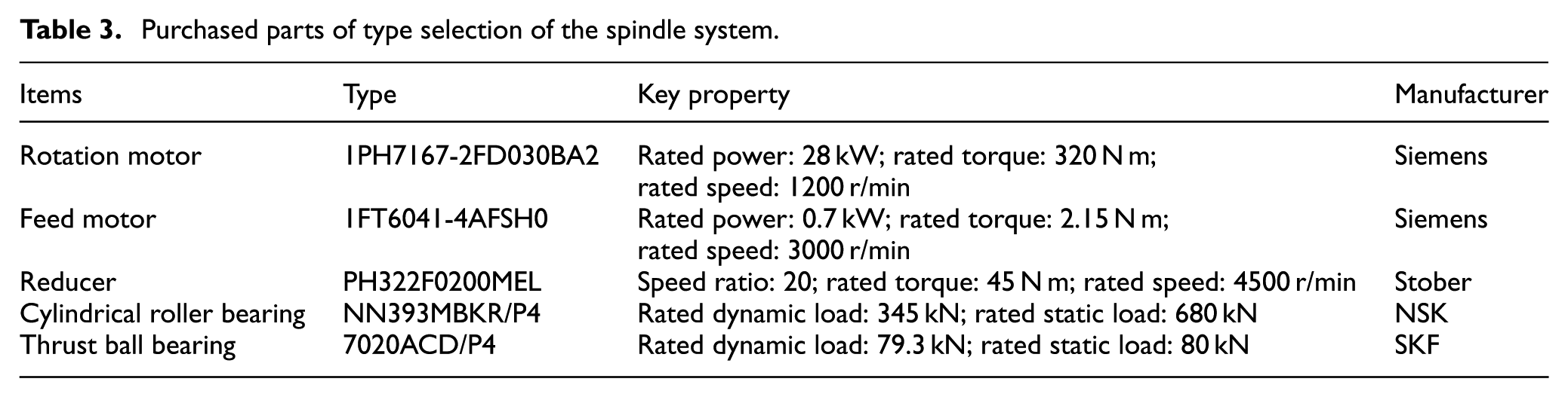
A multi-stage planetary reduction plan is used to increase the output torque to resist the friction moment during welding. The design requirements can be satisfied by checking the tooth surface contact fatigue strength and tooth root bending fatigue strength. The telescopic shaft is designed to have high-precision fine screw transmission, and it is supported by two types of bearings, which can transfer the external welding load to the spindle box using its reverse self-locking function. Three feed motors and three planetary gears are distributed uniformly along the circumference, which could convert the driving moment into the insert force. Furthermore, a linear rolling guide rail is installed on each motor, which can play the role of enhancing guidance and increasing stability. In addition, there is an absolute encoder installed on the end of each motor. It is used to position the axial movement and the spindle speed. The main purchased parts of type selection of the spindle system are given in Table 3.
Purchased parts of type selection of the spindle system.
The maximum feed speed must be calculated by other design parameters, as shown in equation (1)

Here, Sscrew-pitch = 8 mm is the screw pitch, igear = 20 is the reduction ratio of the planetary transmission mechanism, and ireducer = 20 is the reduction ratio of the speed motor. Because the rated output speed is nfeed-montor = 3000 r/min, the insert velocity of the spindle can meet the design requirements. For the rotation shaft, the rated speed and the rated torque are directly subjected to the parameters of the spindle motor. As shown in Table 2, the rated speed and the rated torque of the rotation motor are all in accordance with the designed indexes.
Friction stir weld thermal–mechanical coupling simulation
The FSW process is essentially nonlinear owning to its high temperature and large strains, as well as the materials’ plastic behavior in the welding zone. The complexity of the friction condition at the interface between the material and the tool increases the difficulty of modeling the process. Conventional implicit finite element method can solve a real quasi-static equation. However, in the computation of the FSW solutions, the traditional method would produce multidimensional linear matrix equations, which must be solved through the establishment of many single load steps. 19 The irregular frictional contact between interfaces will increase the difficulty of obtaining solutions, making the convergence of each load step extremely difficult and tremendously time-consuming. 20 The explicit finite element method is basically a dynamic solving program, which applies explicit time integrals to discrete motion equations. The explicit methods, such as the integration method about time, are different from the implicit method mentioned previously, due to the fact that in those methods it eliminates the need to solve the time-consuming inverse matrix operation. The heat generated during FSW is derived from the materials plastic deformation caused by the friction between the welding head and the workpiece. 21 To make the FSW simulation process much more actual and credible, a simultaneous thermal–mechanical coupling analysis is recommended. With increasing temperature, additional stress and thermal expansion will arise in the material. It is necessary to consider these factors. Coupled temperature–displacement analysis is the most suitable analysis for the simulation of FSW and, therefore, is applied in this study.22,23
The finite element engineering simulation software ABAQUS provides several options for both thermal and mechanical analyses. 24 Using coupled temperature–displacement analysis, it is possible to solve the stress/strain field and temperature field at the same time. In ABAQUS, explicit positive time-difference rules were used to compound transfer functions and to use explicit central difference rules to obtain the mechanical response.
ABAQUS/Explicit can solve the initial dynamic balance state of the current time increment t 25

where

The central difference integration principle is used to update the velocity and the displacement, as shown in equation (4)

The resulting stability depends on the minimum time step size, which is approximately equal to the minimum transmission time of the dilatational waves in the grid, as shown in equation (5)
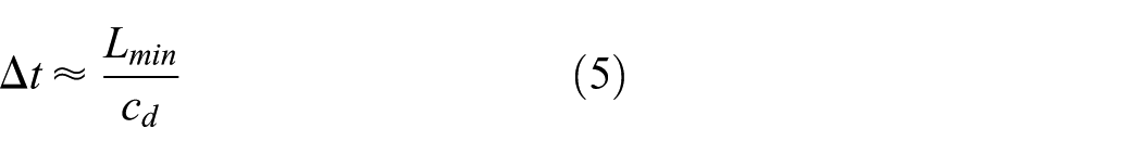
where Lmin is the size of the smallest element in grid and cd is the wave velocity. The expression of cd is shown in equation (6)

Here, ρ is the material density, and λ and µ are the empirical constants. In ABAQUS/Explicit, the heat transfer equation is synthesized through the explicit positive time integration principle, as shown in equation (7)
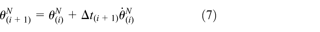
where
A type of material-constitutive model, called the Johnson–Cook equation, is used to establish the flow stress–strain relations with the change in temperature (equation (8))

where
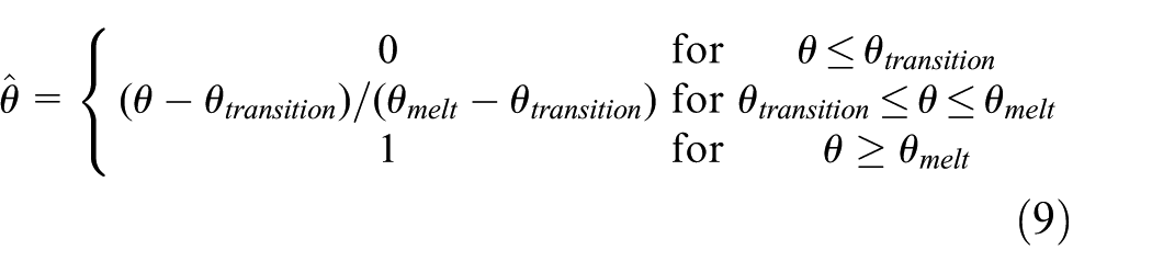
where θ is the current temperature, θmelt is the melting temperature, and θtransition is the transition temperature. 26 The aluminum alloy 2024-T4 was used as an example, to study the numerical simulation of the FSW process. The thermal and mechanical properties of aluminum alloy 2024-T4 are given in Table 4.
Material properties of AL2024-T4.

The influence of the temperature on material properties cannot be ignored in the simulation of the thermal–mechanical coupling process. To improve the accuracy of the calculation, the thermal conductivity and specific heat capacity of AL2024-T4 material depend on the temperature and are taken into account as shown in Figure 3.

AL2024-T4 relation curves of thermal conductivity and specific heat capacity versus temperature.
The data points of the thermal conductivity and temperature as well as the specific heat capacity and temperature are given in Table 5. 27
AL2024-T4 relationship of thermal conductivity and specific heat capacity versus temperature.
The FSW configuration model is shown in Figure 4, using a single integral plate instead of two butt plates to create a continuous model. The workpiece thickness is 9.5 mm. The stir-pin is tapered, with minimum diameter of 5.6 mm and maximum diameter of 11.1 mm. The shoulder diameter is 25.4 mm. The simulation of the FSW process includes three stages: plunging, dwelling, and transverse movement. The workpiece can be simulated using an eight-node 3D temperature and displacement coupling element C3D8RT.

Model configuration of FSW simulation.
In the above finite element model, the adaptive domain is taken into consideration for the whole model, and the upper surface contacting with the tool is defined as the sliding area. The grid follows the material as it moves along the normal direction in relation to the surface and moves independently in the tangent direction.
Using a contact coupling algorithm, the contact between the tool and the workpiece as well as between the workpiece and the backing plate is simulated. At the interface between the tool and the workpiece, the Coulomb friction law can be used with constant friction coefficient. 27 The backing plate is completely fixed and the bottom surface of the workpiece is constrained such that no rigid body motion arises. At the beginning of the analysis, the environmental temperature of the model is assumed to be a constant temperature field. It is assumed that all surfaces of the workpiece meet convection boundary conditions. The convection coefficient between the workpiece bottom surface and the backing plate is 1012 W/m2 K, and that between all other surfaces is 10 W/m2 K. 28
The tool penetration rate is 30 mm/min and the plunging time is 18 s, which is equivalent to sinking 0.1 mm after penetrating the workpiece. The next 2 s corresponds to the dwelling stage. Two seconds is an adequate timespan because it mainly contributes to generate appropriate heat and to keep the welding material in good plasticizing state. The latter can also ensure welding quality. 29 The welding speed and welding time in the transverse phase are set to 75 mm/min and 10 s, respectively.
To initially avoid sudden lateral movements of the tool, the transverse speed is limited by the values of each time point in ABAQUS, as shown in Figure 5. Figure 5 shows the relationship of the tool speed and time during the three stages of the FSW.

FSW tool velocity versus time in the three stages.
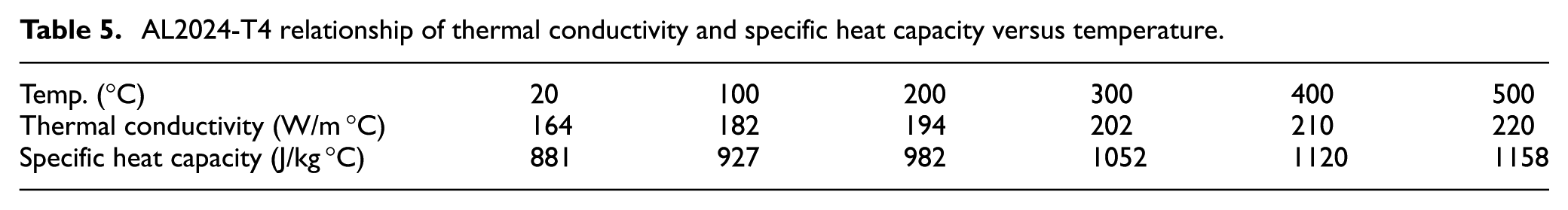
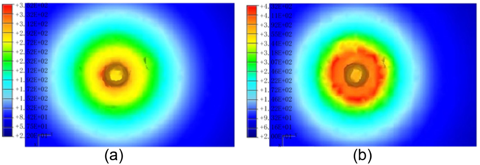
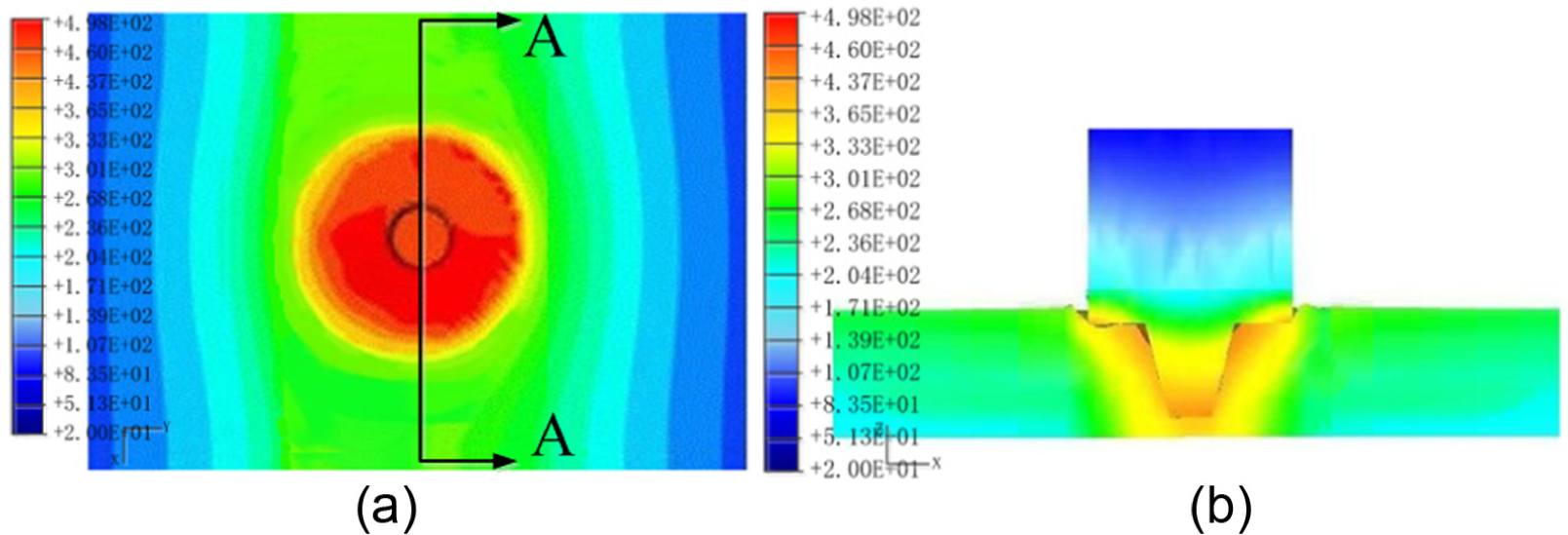
Figures 6–8 show the temperature distribution of five representative time points: 12, 18, 20, 27, and 30 s. Note that the plunging phase occurs between 0 and 18 s, dwelling phase occurs between 18 and 20 s, and the transverse phase occurs from 20 to 30 s.
Numerical simulation of the FSW process—plunge (°C): (a) t = 12 s and (b) t = 18 s.
Numerical simulation of the FSW process—dwell (°C): (a) t = 20 s and (b) Section A-A.
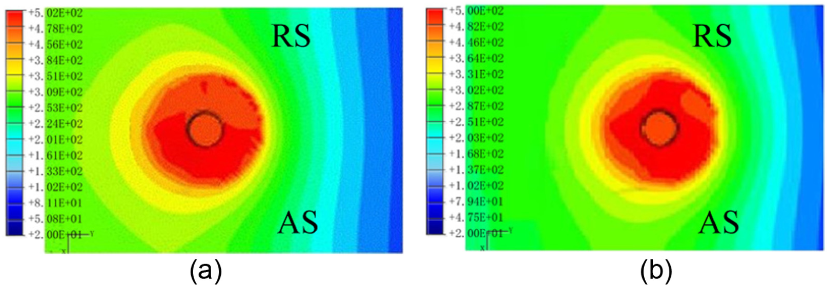
Numerical simulation of the FSW process—transverse (°C): (a) t = 27 s and (b) t = 30 s.
Figure 7(b) gives the cross-sectional views along the welding joint line, while the rest of the pictures provide the views from the top. When only the stir-pin contacts with the workpiece, the highest temperature occurs near the bottom edge of the stir-pin. At 17.8 s, the tool’s shoulder starts to contact with the workpiece, and the highest temperature appears in the corner between the shoulder and the stir-pin. At 18 s, contact is completely established between the workpiece upper surface and the tool outside surface. The highest temperature occurs around the interface between the tool’s shoulder and the workpiece.
A “V” shape temperature gradient arises from the workpiece cross section. This shows that high-intensity heat flow exists at the interface layer between the tool’s shoulder and the workpiece. After 2 s of dwelling, the temperature distribution is more remarkable between the tool’s trailing side and leading side. Therefore, the tool moves laterally to connect the plates together. The welding process reaches steady state quickly, and the tool’s temperature distribution shows little change, as shown in Figure 8 at 27 and 30 s.
As it can be seen from Figure 8, the temperature contour is asymmetrical between the retreating side (RS) and the advancing side (AS). The higher processing temperatures are achieved on the AS, and the maximum temperature difference can reach about 10°C.
In the steady-state transverse phase, the highest temperature is 502°C. At this phase, the temperature is slightly higher than the melting point of AL2024-T4 (its melting point is about 500°C). If work is performed in such conditions, the material is still solid and there will be no welding defects. At the same time, the material also fully embodies the advanced nature of FSW welding technology.
In the simulation process, a larger deformation usually occurs in the elements near the tool, especially in the plunging phase. The decrease in particular element’s length will lead to a small global time increment, thus increasing the working time. A decrease in the mass can significantly reduce the computational cost in the analysis. Therefore, assuming that the final time of the simulation is 18 days 10 h, mass reduction is essential to obtain a solution within a reasonable timespan.
FSW spindle heat transfer analysis
Because the welding process can generate a very high amount of heat over time, heat would gradually be transferred to bearings and motors inside the spindle. Once the temperature exceeds the allowable values for these components, it will have a significant impact on the working information of the spindle system. The purpose of the temperature field analysis for the spindle system is to determine how long these components can maintain the critical temperature. These data are the basis of temperature type-selection design, which can ensure that the spindle system works securely and credibly. The finite element model of the FSW spindle is established in the Gambit software, as shown in Figure 9. Before meshing is carried out, some necessary geometric simplifications need to be carried out to obtain the best grid quality to ensure the reliability of the analysis results. The simplified principle of the geometric model is as follows:
Remove or simplify the complex and tiny features of the model. The outline shape must be as a rule as possible.
Remove the local bolts, threads, holes, and various forms of chamfers.
The ball or cylindrical bearing should be simplified as one body structure with “H” section.
Ensure fewer grid numbers, but the mesh quantity of the key position should be close enough.
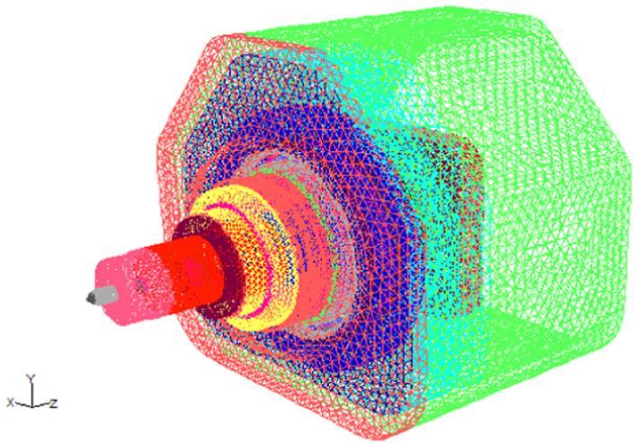
The FEM model of the FSW spindle.
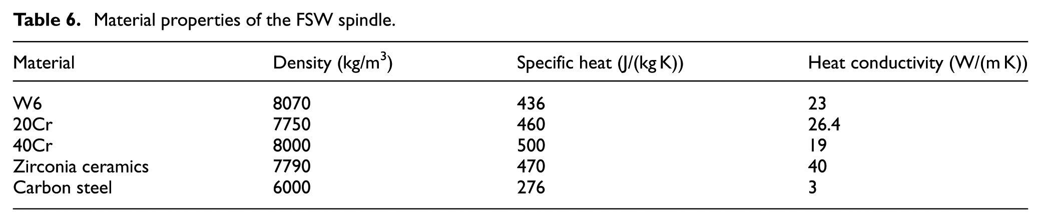
The materials of the FSW spindle and their physical properties are shown in Table 6:
Material properties of the FSW spindle.
Using Fluent software to simulate the temperature distribution, the boundary conditions are defined as follows:
Natural convection heat transfer coefficients of 10 and 0.5 W/(m2 K), corresponding to the exposed surfaces and some inner surfaces of the FSW spindle, respectively. The environment temperature is considered to be 27°C (300 K).
Constant temperature heat source boundary condition: the highest temperature on the contact surface between the stir-pin shoulder and the workpiece is considered to be 500°C (773 K), according to the FSW process test, presented in section “Friction stir weld thermal–mechanical coupling simulation.
Thermal insulating boundary conditions: the closed inner area and the surfaces with poor heat transfer conditions are considered.
Interior boundary conditions: the interface between the different parts.
The locations of interest for heat transfer analysis are the front angular contact ball bearings and the fitting surface between the rotation motor shaft and the main driving shaft. Considering the different amounts of heat generation required to weld various materials, without loss of generality, the four different welding heat source temperatures are given, to analyze the steady temperature field results on the above locations, as shown in Table 7.
Steady temperature field results of the FSW spindle with ceramic heat insulation layer (°C).

Herein, considering 500°C as a heat source condition as example, the steady temperature field distribution of the FSW spindle is shown in Figure 10. Figure 10(a) represents the temperature nephogram of the cross section. Among this, AB section is the inner ring of front angular contact ball bearing, BC section is the middle piece of main driving shaft, and CD section is the fitting surface between rotation motor and main driving shaft. We especially focus on the AB and CD sections. Figure 10(b) shows the path diagram of steady temperature distribution along AD section, and, as we can see from the diagram, the spindle temperature gradient is obvious.

Steady temperature field results under 500°C: (a) cross-sectional temperature nephogram and (b) path diagram of AD section.
From the above results, the least heat is passed to the rotation motor, and the highest temperature, which occurs on the motor shaft surface, is 40°C. However, the rolling bearing temperature on the spindle, especially the front angular contact ball bearing temperature gradient, is more significant. Under 500°C heat source condition, the highest temperature of the outer ring of the front angular contact ball bearing can be up to 54°C, and the highest temperature on the inner ring can be up to 63°C. These temperature results are less significant for rotation motor type selection and relatively harsh on the front angular contact ball bearing.
Because the heat transfer is a continuous process, with the increase in welding time, the friction heat finally reaches temperature-sensitive components. To slow down heat transfer speed, all welding tasks should be completed as soon as possible before thermal equilibrium. Therefore, even if the temperature referred above is beyond the maximum temperature at the bearing and at the motor itself, it can still perform specific welding tasks over a period of time. That is true, because the highest temperature is still lower than the allowable value for temperature-sensitive components.
To extend the working time of welding, a ceramic heat insulation layer with low thermal conductivity is placed between the stir-pin and the main driving shaft. Its material is zirconia, which is a material that can effectively delay the welding heat transferred upward. To compare the heat insulation effect with or without ceramic layer, the transient thermal analysis of the FSW spindle is carried out under 450°C and 500°C. The transient-temperature field results for different working hours of the FSW spindle without ceramic heat insulation layer are as shown in Table 8.
The transient-temperature field results of the FSW spindle without ceramic heat insulation layer (°C).
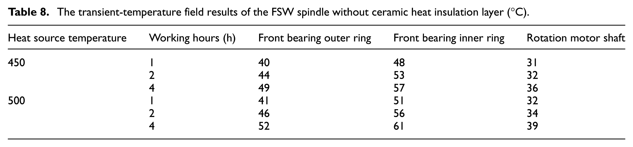
Under the 450°C heat source condition, the temperature field of the FSW spindle becomes gradually steady after 4 h, the inner ring temperature of the front angular contact ball bearing is 57°C, the outer ring temperature is 49°C, and the highest temperature on the rotation motor shaft is 36°C. When subjected to the 500°C heat source condition, the temperature field also tends to be steady in 4 h, the inner ring temperature being 61°C, the outer temperature 52°C, and the highest temperature on rotation motor shaft 39°C. Compared with the two kinds of working conditions, the former is 4°C lower in average than the latter for front angular contact ball bearing and 3°C for the output shaft of the rotation motor. The transient-temperature field results for the FSW spindle with ceramic heat insulation layer for different working hours are shown in Table 9.
Transient-temperature field results of the FSW spindle with ceramic heat insulation layer (°C).

Under the 450°C heat source condition, the temperature field of the FSW spindle has not reached steady state after 4 h, the inner ring temperature of front angular contact ball bearing is 53°C, the outer ring temperature is 45°C, and the highest temperature on the rotation motor shaft is 35°C. When subjected to 500°C heat source condition, the temperature field does not become steady within 4 h, the inner ring temperature is 56°C, the outer temperature is 47°C, and the highest temperature on rotation motor shaft is 37°C. Comparing the results of these two working conditions, the former is 3°C lower in average than the latter for front angular contact ball bearing and 2°C for the output shaft of the rotation motor.
From the above analysis, we can find that the ceramic heat insulation layer has played a role in delaying rises in temperature. Under the 450°C heat source condition, temperature tends to quasi-steady state after 4 h. Compared with the highest temperature of the front angular contact ball bearing without ceramic heat insulation layer, there is a decrease in 6°C. Under the 500°C heat source condition, the role of the ceramic heat insulation layer still exists after working 4 h, and it is almost 7°C lower than the highest temperature of the front angular contact ball bearing without ceramic heat insulation layer. But due to the higher heat source temperature and larger heat generation rate, the two kinds of working conditions always reached steady state when they worked continuously for a period of time. To ensure the welding quality and avoid component damage due to overheating, we should perform essential derating design.
Welding experiment results
To verify the heat transfer simulation results of the FSW spindle, we integrate the FSW spindle system introduced in section “The FSW spindle system” and a particular welding robot for welding large-scale complex surface structures. The FSW robot is shown in Figure 11.

FSW robot.
The robot is developed using a redundant design concept for the joints, and it is composed of one 3-DOF Cartesian arm, 2-DOF wrist, 2-DOF spindle, and 1-DOF rotary, controlled by a Siemens SINUMERIK 840D controller. This robot has the ability of eight axes’ linkage and single axial independence movement.30,31
Taking advantage of the welding technology parameters and the workpiece geometric sizes, continuous welding is carried out on a flat sheet of aluminum alloy 2024. To compare the experimental results with simulation results, a temperature sensor is installed on the outer ring of the front angular contact ball bearing to obtain real-time temperature at different welding time instants. The real-time data of the front bearing outer ring of the FSW spindle can be displayed by a temperature recorder, as shown in Figure 12. After completion of welding, the weldment of AL2024-T4 sheet is shown in Figure 13. Through careful observation of the appearance and cross section of weld seam, the welding effect is satisfactory.
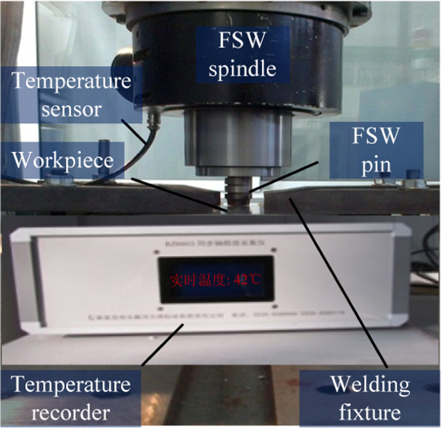
Real-time temperature data of the outer ring of front angular contact ball bearing.

Weldment of AL2024 sheet.
To show the results of the transient-temperature field of the FSW spindle with ceramic heat insulation layer under the 500°C heat source condition, we set the temperature sensor sample once every 1000 s and draw these sampling points into curve. The two curves are displayed together, as shown in Figure 14.

Contrast of simulation and experimental curve.
As can be seen from Figure 14, the test curve and the simulation curve are basically identical. The difference is that the experimental temperature values are slightly lower than the simulation analysis results. The main reason is that the heat source acting on the stir-pin is lower than 500°C, which is the boundary condition, given the friction stir and the plastic behavior of the material, at the beginning,. This process would need a certain amount of time. Within the next 50 min, the slopes of these two curves grow significantly and the temperature transmission speed increases significantly. The most straightforward interpretation is that the uninterrupted heat generation and the maximum temperature difference occur between the front bearing and the stir-pin. At the end of the period, the two curves are close to each other and tend to be straight. The temperature ascension space is limited due to the arrival of the steady temperature field and the approximate thermal equilibrium.
In addition, the joint quality is the key to demonstrate whether the new FSW spindle system works well. In this article, the mechanical performance is evaluated by comparing two indexes, including tensile strength and elongation, between AL2024-T4 BM and the joint. Figure 15 displays the tensile properties of three sample joints. Sample 1 joint presents a tensile strength of 463 MPa, equivalent to 96.4% of that of BM (its tensile strength is 480 MPa). In contrast, the tensile strength of sample 2 joint is 476 MPa, reaching 99.1% of that of BM, and the tensile strength of sample 3 joint is 471 MPa, reaching 98.2% of that of BM. The elongations of the three sample joints are, respectively, 8.1%, 8.5%, and 8.8%, which are comparable with the elongation of BM (its elongation is 12%).

Mechanical properties of the three sample joints.
In contrast, we found out that the tensile strength of the three kinds of sample joints is basically close to the tensile strength of BM, and there is a slight drop in the elongation. The average strength of AL2024-T4 is 470 MPa, reaching nearly 98% of that of BM, and the average elongation is about 8.47%, equivalent to 7% of that of BM. The two indicators reveal that the weld joint formed by this kind of new type of FSW spindle system has better mechanical properties and can satisfy the engineering application requirements for reliability and durability.
Figure 16 shows the fracture features of the three sample joints. Here, the RS is located at the left of every fracture sample, and the AS is located at the right. As it is possible to see, the three tensile samples are all fractured in the AS, the oblique fracture surface, and the tensile direction is nearly 45°.

Fracture location on the three sample joints.
Conclusion
In this work, a new type of 2-DOF FSW spindle system is introduced for large-scale complex surface structures, including one telescopic DOF that the welding tool plunges into the workpiece and one rotation DOF that generates friction heat. The structure design has the characteristics of heavy-load resistance and high stiffness.
Furthermore, the thermal–mechanical coupling model is established between the stir-pin and the workpiece, the heat generation and transfer process are simulated, and the temperature field distribution results for components of interest inside the FSW spindle are obtained and verified by experiments.
It is believed that the newly developed FSW spindle can be applied for welding large and complex welded Al structures in the aerospace field. The test curve and the simulation curve are basically identical. The resulting data can provide reliable reference design and type selection of temperature-sensitive components, such as angular contact ball bearings and rotation motors. Furthermore, the mechanical properties of the weld joint are basically close to the tensile strength of BM and can satisfy well the engineering application requirements for reliability and durability.
In future work, we are going to improve the spindle autonomy in two ways. In the first place, a seam-tracking system will be added into the system. In the second place, force sensors and torque sensors will be added to the 2-DOF spindle, to achieve force/position hybrid control.
Footnotes
Academic Editor: Jose Ramon Serrano
Declaration of conflicting interests
The author(s) declared no potential conflicts of interest with respect to the research, authorship, and/or publication of this article.
Funding
The author(s) disclosed the receipt of the following financial support for the research, authorship, and/or publication of this article: This research was supported by the National Natural Science Foundation of China (grant nos 51505470 and 11602283) and Dr Start-up Fund in Liaoning province (no. 20141152).