
Abstract
In this study, friction stir welding window for AA6061-T6 aluminium alloy based on tool rotational speed and weld speed was developed. The formation of friction stir welding/processing zone has been analysed macroscopically and microscopically. Fracture locations of the joints were also analysed using scanning electron microscope. It has been experimentally found that the joint fabricated using tool rotational speed of 1000 r/min and weld speed of 40 mm/min (obtained from friction stir welding window), tool shoulder diameter of 24 mm with tapered cylindrical pin profile and the ratio of shoulder to pin diameter with value 3 showed better mechanical properties compared to other joints. The developed welding window will be used as ready reckoner to select appropriate rotational and welding speed to fabricate defect-free joints.
Introduction
Heat-treatable wrought aluminium–magnesium–silicon (Al-Mg-Si) alloys conforming to AA6061 are of moderate strength and possess excellent welding characteristics over the high-strength aluminium alloys. Hence, alloys of this class are extensively employed in marine frames, pipelines, storage tanks, 1 defence and aerospace applications. 2 Friction stir welding (FSW) is a novel solid-state welding process for joining metallic alloys and composites and has enormous potential in manufacturing applications. 3 Advantages of this technique include joining of materials that are difficult to fusion weld, low distortion and excellent mechanical properties. 4,5 During FSW, a rotating tool moves along joint interface, generates heat and results in recirculating flow of plasticized material near the tool surface. This softened material is subjected to extrusion by the tool pin rotational and traverse movements leading to formation of friction stir processing (FSP) zone. The formation of FSP zone is affected by the material flow behaviour under the action of rotating tool. However, the material flow behaviours are predominantly influenced by the material properties such as yield strength (YS), ductility and hardness of the base metal (BM), tool design and FSW process parameters. 6 There have been lot of efforts to understand the effect of process parameters on material flow behaviour, microstructure formation and hence mechanical properties of FSWed joints. The effect of process parameters such as weld speed, rotational speed and axial force on mechanical properties and microstructure of AA6061 alloy was already studied by past researchers 1,7 –10 using different pin profiles. Furthermore, it was reported that using square (SQ) pin–profiled tool exhibited superior mechanical properties. However, from the manufacturing point of view, the SQ pin is extremely difficult to manufacture as far as cost and time are concerned. In addition to this, stress concentration is more at the corners of the SQ pin profile. Although these exotic and complicated tool geometries can be optimized to achieve the desired weld quality, consistency in the long run becomes difficult to maintain because of wear and tear of the tool pins. 11 On the other hand, straight cylindrical (SC) and taper cylindrical (TC) pin–profiled tool can even be produced on ordinary lathe machine. In addition to this, past researchers have used high-carbon steel (HCS) as a tool material, and tilt angle was fixed to normal to weld plate. Again from the reported literature, it is seen that many past researchers 12 have used H13 hot-worked tool steel as a tool material. From the literature, it is understood that the problem of selection of process parameters is not fully dependent on machine controls rather it is material dependent. A suitable selection of process parameters for the FSW process relies heavily on the operators’ technologies and experience because of their numerous and diverse range. FSW parameters are selected by trial-and-error (or Jugaad 13 ) method required to fix the working range to get defect-free welds; also, it do not provide the optimal range of parameters. Hence, there is an ardent need to construct friction stir welding window (FSWW), which will be useful as a ready reckoner to select appropriate rotational and welding speed to fabricate defect-free joints.
Preheating or cooling can also be important for some FSW processes. For materials with high melting point such as steel and titanium or high conductivity such as copper, the heat produced by friction and stirring may not be sufficient to soften and plasticize the material around the rotating tool. Thus, it is difficult to produce continuous defect-free weld. In these cases, preheating or additional external heating source can help the material flow and increase the process window. On the other hand, in materials with lower melting point such as aluminium and magnesium, cooling can be used to reduce extensive growth of recrystallized grains and dissolution of strengthening precipitates in and around the stir zone (SZ). 4
In order to identify the process parameters that affect the quality of weldments by FSW, an Ishikawa cause–effect diagram was constructed as shown in Figure 1. The parameters can be classified as follows.
Tool design. Tilt angle, pin geometry, plunge depth, shoulder (D)-to-pin diameter (d) ratio (D/d), tool material, its composition, physical and mechanical properties, shoulder geometry, shape, pin length and so on.
Clamp design. Clamp force, plate thickness variation, clamp geometry, thickness mismatch and so on.
Machine-based parameter. Tool rotational speed, weld speed, weld gap, that is, gap between upper part of work and lower part of shoulder and so on.
Workpiece-based parameters. Material, its composition, physical and mechanical properties, size, shape and so on.
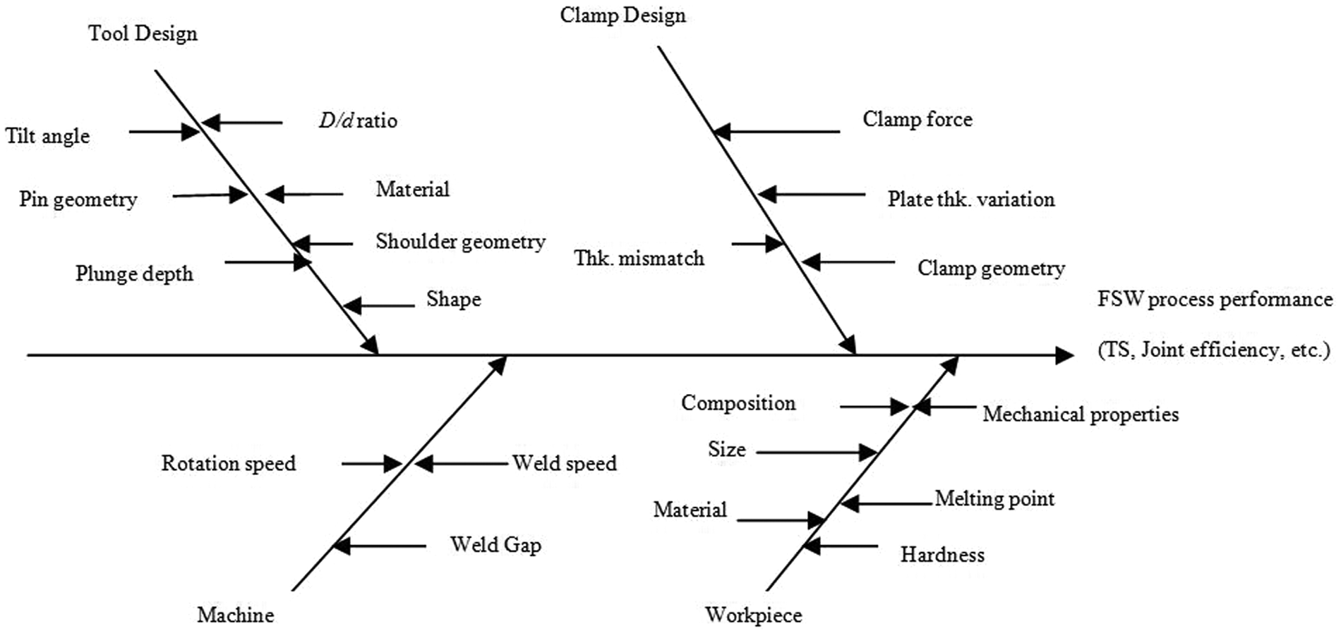
Cause–effect diagram.
The influence of the process parameters such as tool rotational speed (N) and weld speed (ν), shoulder diameter (Ds ), pin diameter (Dp ), ratio of Ds/Dp and tool pin profile on weld properties has been investigated in this study. The purpose of this investigation is to study the effect of process parameters on mechanical properties of FSWed joints. The concept of interval reducing method was applied to find optimum range of process parameters because it reduces the interval of uncertainty successively to a small acceptable value. 14
Experimental work
Fabrication of joints
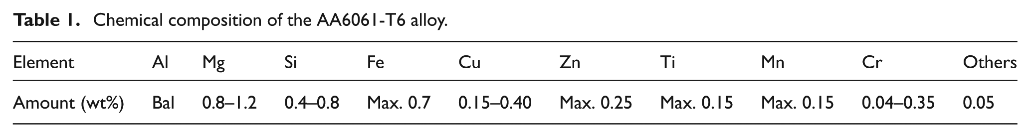
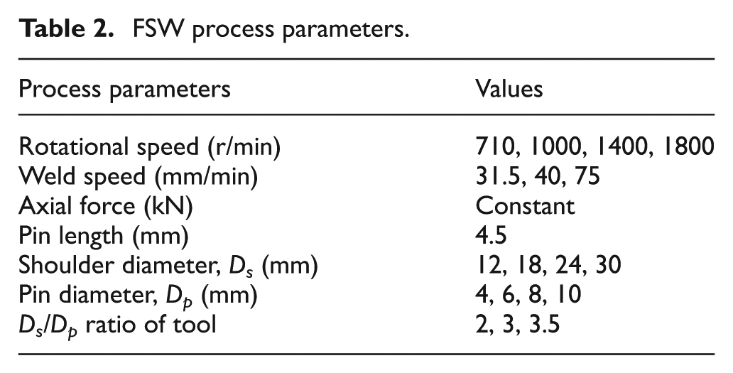
The BM employed in this study is 200 mm × 100 mm × 6 mm thick AA6061-T6 aluminium alloy. A non-consumable tool made of H13 tool steel is used to fabricate joints. The chemical composition of the BM is shown in Table 1. The welding process is carried out on a vertical milling machine (make: HMT FM-2, 10 hp, 3000 r/min). Table 2 depicts the combinations of the tool rotational speed (N), weld speed (ν) and shoulder diameter/pin diameter (Ds/Dp ) ratio selected for this study. These combinations are chosen based on the capability of the milling machine used for the experimental study. The tools used for this study are SC and TC with shoulder and pin. The pin is specially designed with taper profile and is accommodated in a predrilled hole along the weld interface. A constant axial force is used to fabricate all the joints.
Chemical composition of the AA6061-T6 alloy.
FSW process parameters.
The direction of welding is normal to the rolling direction. Single-pass welding procedure is used to fabricate the joints. After welding, non-destructive testing (NDT) (X-ray radiography) was performed to detect any defects in the weldments. Joints were fabricated using different combinations of rotational speed and welding speed.
Characterization of welded joints
Specimens for tensile testing (notched specimens) were taken at the middle of all the joints in the traverse direction from the welded joints and machined to ASTM: E8/E8M-011 standards. Tensile test was conducted using computer-controlled universal testing machine (make: Shimadzu, model: Autograph) with a cross-head speed of 0.5 mm/min. All the welded specimens were failed in the weld region. The ultimate tensile strength (UTS) of the weld joint is the strength of the weld. BM mechanical properties are shown in Table 3.
Mechanical properties of AA 6061-T6 alloy.
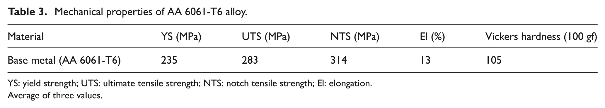
YS: yield strength; UTS: ultimate tensile strength; NTS: notch tensile strength; El: elongation.
Average of three values.
Specimens for metallographic studies and micro-hardness tests (15 mm width) were considered at the middle of all the joints. The specimens were suitably sectioned, mounted, mechanically polished according to standard metallographic procedures and are etched using modified Keller’s reagent (2 mL HF, 3 mL HCl, 20 mL HNO3 and 175 mL H2O). Microstructural analysis was carried out after deep etching the specimens using optical microscope (make: Leitz) with image analysing software (Biovismat). Micro-hardness tests were carried out on the welded samples with a load of 15 gf and a duration of 15 s using a Vickers digital micro-hardness tester (make: Shimadzu, model: HMV-2000). The micro-hardness was measured at an interval of 0.5 mm across the weld, 1 mm across the heat-affected zone (HAZ) and 1.5 mm across the unaffected BM. Sub-sized (5.5 mm thick) Charpy V-notch impact specimens were prepared and tested in accordance with BS EN 10045-1:1990. The specimens were prepared with the same orientations and notch tip positions (except for the thermo-mechanically affected zone (TMAZ)/SZ interface position) as the corresponding fracture toughness specimens as shown in Figure 2.
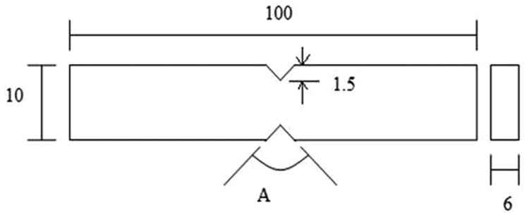
Schematic diagram of notch tensile specimen (where A = 60°; all dimensions are in ‘millimetres’).
The mechanical properties such as UTS, YS, percent elongation (%El), notch tensile strength (NTS) and joint efficiency (ηJoint) of the weldments were evaluated for all the combinations.
Results
The macrographs of weld zone of four different tool rotational speeds, that is, 710, 1000, 1400 and 1800 r/min, are presented in Table 4. The other parameters such as weld speed, axial force and tool shoulder diameter were kept constant. From the observation, it was found that tool rotational speeds 710, 1000 and 1400 r/min produced defect-free joints. The probable reasons for all the conditions are explained in Table 4. The defect-free weldments are subjected to tensile tests.
Effect of tool rotational speed on FSP zone formation in AA6061-T6 (weld speed 40 mm/min, Ds : 24 mm).
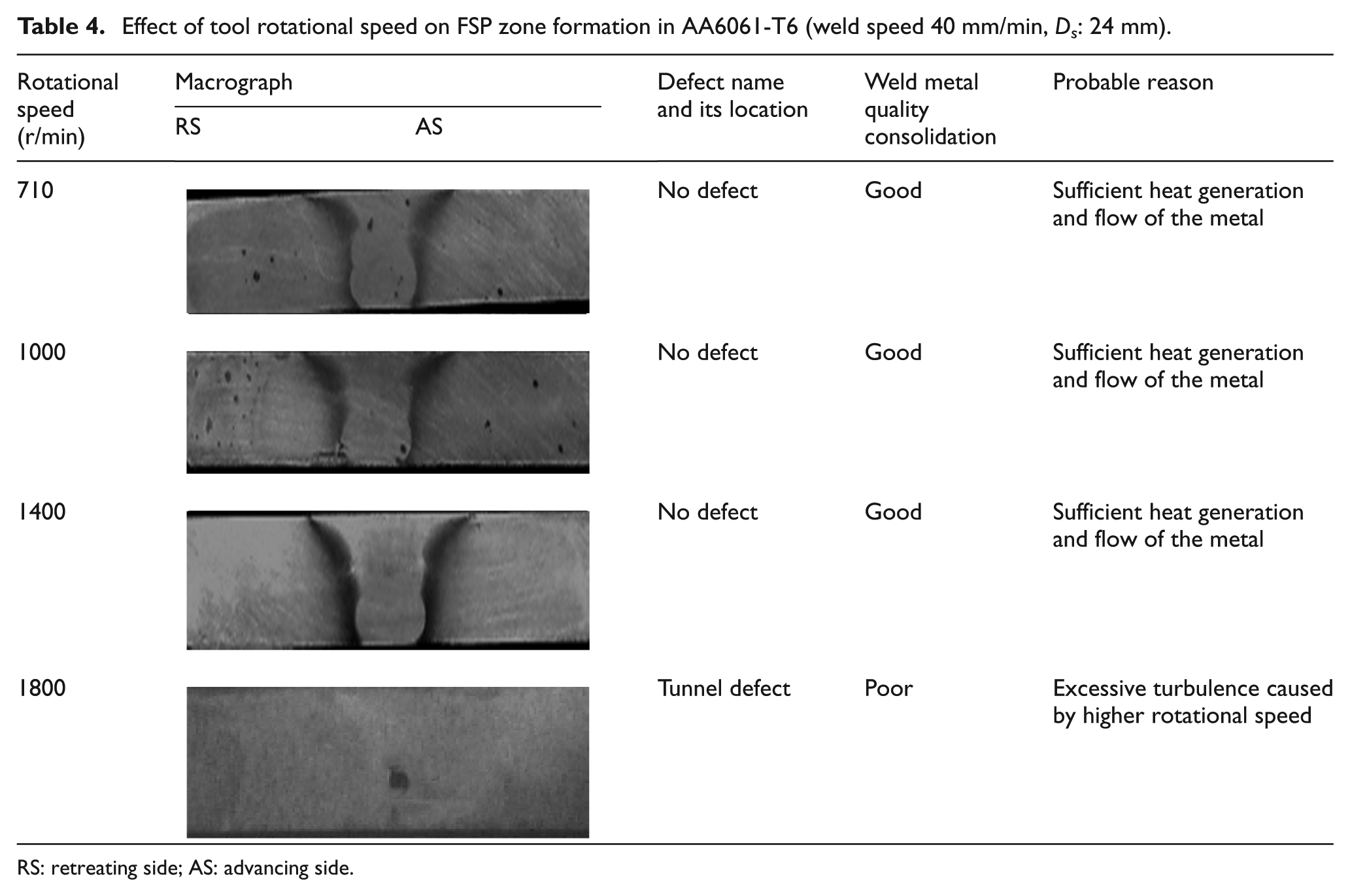
RS: retreating side; AS: advancing side.
The transverse tensile properties such as TS, YS, %El, NTS and ηJoint of AA 6061-T6 aluminium alloy joints were evaluated. In each condition, two specimens were tested, and the average of these results is presented in Table 5. The formation of fine-grain microstructure, uniformly distributed fine precipitates and higher SZ hardness are the main reasons for superior tensile properties of FSW joints. 15 During tensile test, FSW joints failed in the TMAZ/HAZ region where the hardness is low. Further discussion on fracture locations of the joints is presented in this study.
Mechanical properties of the joints fabricated.
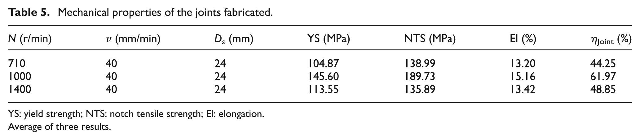
YS: yield strength; NTS: notch tensile strength; El: elongation.
Average of three results.
Discussion
Effect of tool rotational speed
In FSW, tool rotation speed results in stirring and mixing of material around the rotating pin which in turn increases the temperature of the metal. It appears to be the most significant process variable since it tends to influence the weld speed. It was reported that the maximum temperature was observed to be a strong function of rotational speed. 4,5
In order to study the effect of tool rotational speed on the mechanical properties and microstructure, four different speeds were selected keeping in view the speeds available in the vertical milling machine with a constant weld speed 40 mm/min.
The macrostructures were taken at different tool rotational speeds and are shown in Table 4. It is concluded that no defect was observed at 710, 1000 and 1400 r/min due to sufficient heat generation and flow of material. Microstructures revealed after deep etching the defect-free joints are shown in Figure 3(a)–(c). It is seen that fine-grain microstructure is obtained at 1000 r/min and 40 mm/min. The higher TS is also attributed to the uniform distribution of fine eutectic Mg2Si particles in the aluminium matrix of the 16 SZ, whereas the reduction in the strength is due to the coarse eutectic ‘Si’ particles and non-homogeneous distribution in the matrix. This is due to the turbulence of softened metal at higher rotational speeds in which the broken ‘Si’ particles are clustered as coarse and segregated. Micro-hardness is carried out on advancing side (AS) and retreating side (RS) for the three successful weldments, as shown in Figure 4. The average of three results of mechanical properties of weldments at different rotational speeds is presented in Table 5, and it is observed that highest mechanical properties are obtained at 1000 r/min and 40 mm/min.
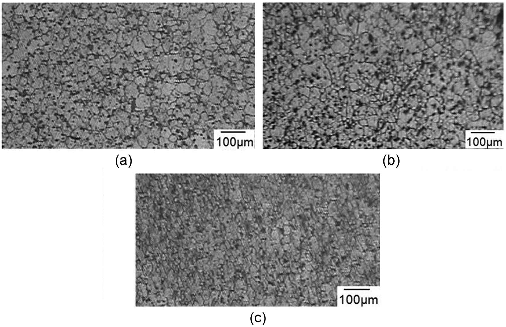
(a) 710 r/min, 40 mm/min, 24 mm (Ds ); (b) 1000 r/min, 40 mm/min, 24 mm (Ds ) and (c) 1400 r/min, 40 mm/min, 24 mm (Ds ).
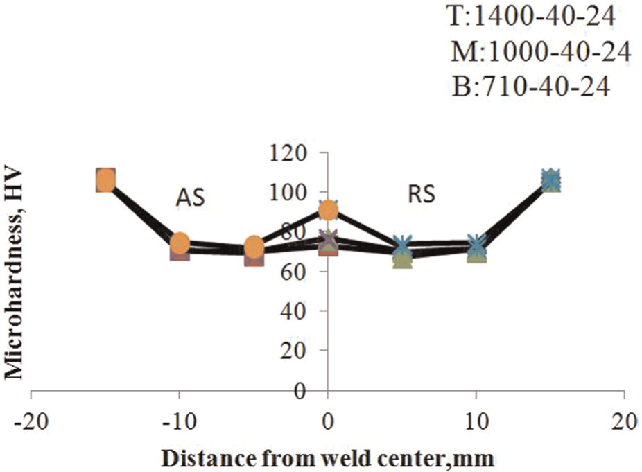
Variation of micro-hardness profiles for different tool rotational speeds (T: top, M: middle, B: bottom curve).
Effect of weld speed
The metal flow phenomenon in FSW comprises two modes of metal transfer. The first mode of metal transfer takes place layer by layer and is caused by the shearing action of the tool shoulder, while the second mode is caused by the extrusion of the plasticized metal around the pin. The translation of tool moves the stirred material from the front to the back of the pin. The rate of heating of thermal cycle during FSW is a strong function of the weld speed. 17 To understand the effect of weld speed on the weld quality and mechanical properties, three different weld speeds were used to fabricate the joints. The macrographs at different weld speed are shown in Table 6.
Effect of weld speed on FSP zone formation (N: 1000 r/min, Ds : 24 mm).
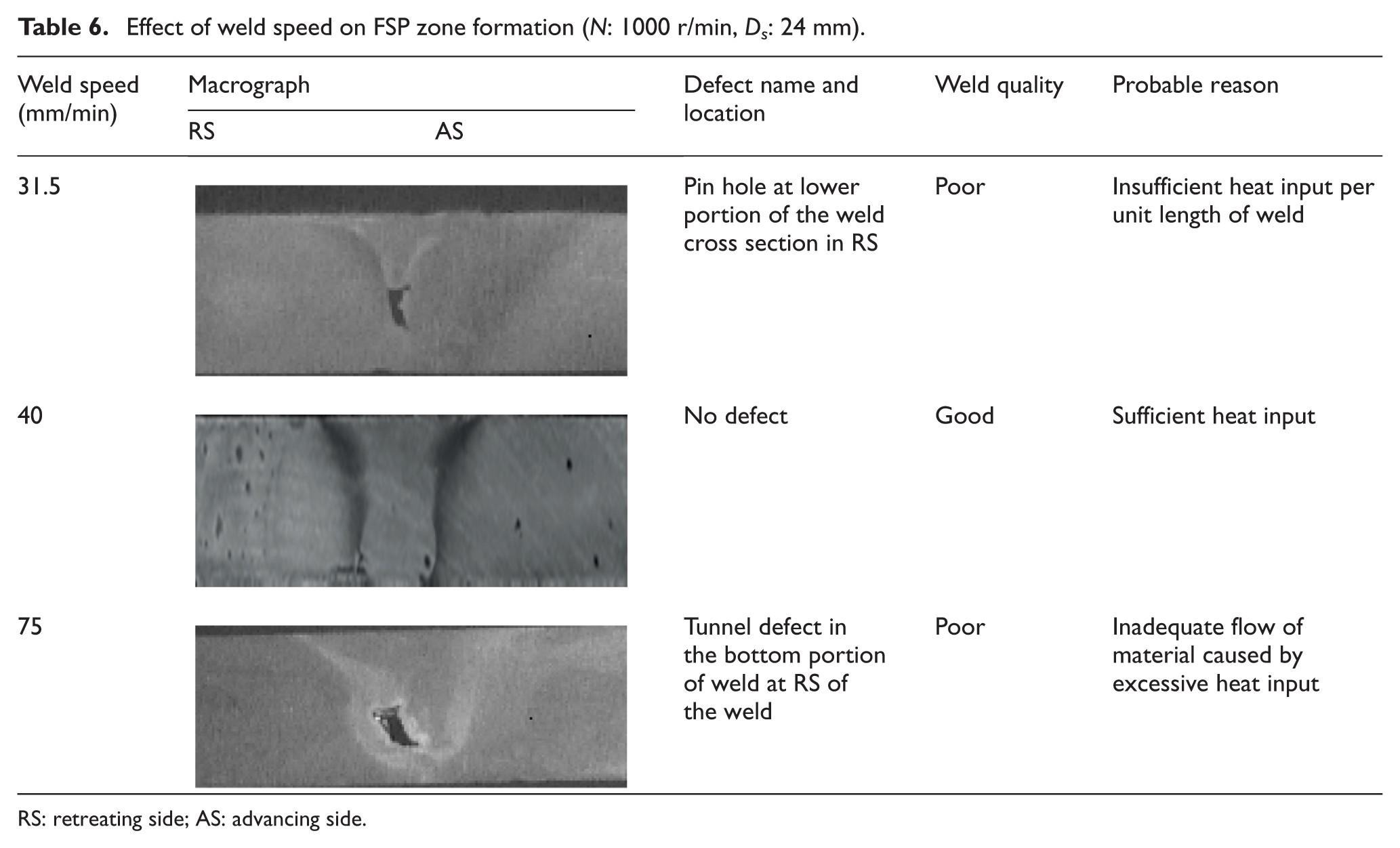
RS: retreating side; AS: advancing side.
From Table 6, it can be seen that pin hole and tunnel defects were observed at lower portion of the weld cross section in RS at weld speed 31.5 and 75 mm/min, respectively. This is due to high and low frictional heat generation under constant rotational speed (1000 r/min). But the joint fabricated at 40 mm/min might have undergone peak ageing due to correct amount of frictional heat generation. 18 This may be one of the reasons for defect-free weld at a weld speed of 40 mm/min compared to their counterparts.
Effect of tool geometry
From the experimental results (macrostructure, microstructure, tensile properties and fracture surface), it is found that the joint fabricated using TC pin–profiled tool with shoulder diameter of 24 mm exhibited superior tensile properties compared to other joints. The reasons for the better performance of these joints are explained below.
Effect of shoulder
From Table 7, it is easily understood that 24 mm shoulder diameter showed maximum η Joint (61.97%), YS (145.60 MPa), NTS (189.73 MPa) and %El (15.16%) than other shoulder diameters. Mehta et al. 19 reported that as the shoulder diameter increases, the state of the deforming material changes from high flow stress and low temperature to low flow stress and high temperature. It has been observed that the larger tool shoulder diameter (30 mm) leads to wider contact area and resulted in wider TMAZ region and HAZ region. On the other hand, smaller tool shoulder diameter (12 mm) leads to narrow contact area. Figure 5 shows the microstructures of 18 and 24 mm shoulder diameters. Of the four different tool shoulder diameters used in this investigation, the joints fabricated using the tool with 24 mm shoulder diameter exhibited superior tensile properties, irrespective of tool pin profiles. The joints fabricated using the tool with shoulder diameter of 18 mm consist of fine, equi-axed grains with uniform distribution of fine strengthening precipitates throughout the matrix. On the contrary, tool with shoulder diameter of 24 mm consists of coarse grains, where the strengthening precipitates (Mg2Si) have become very fine and uniformly distributed throughout the matrix. 1 This may be the reason for higher TS of the joints fabricated using the tool with shoulder diameter of 24 mm compared to their counterparts. The higher values of NTS and %El in case of 18 and 24 mm shoulder diameters may be attributed to correct amount of frictional heat generation, whereas in case of 12 and 30 mm shoulder diameters to low and high frictional heat generation.
Mechanical properties of the weldments welded using different shoulder diameters.
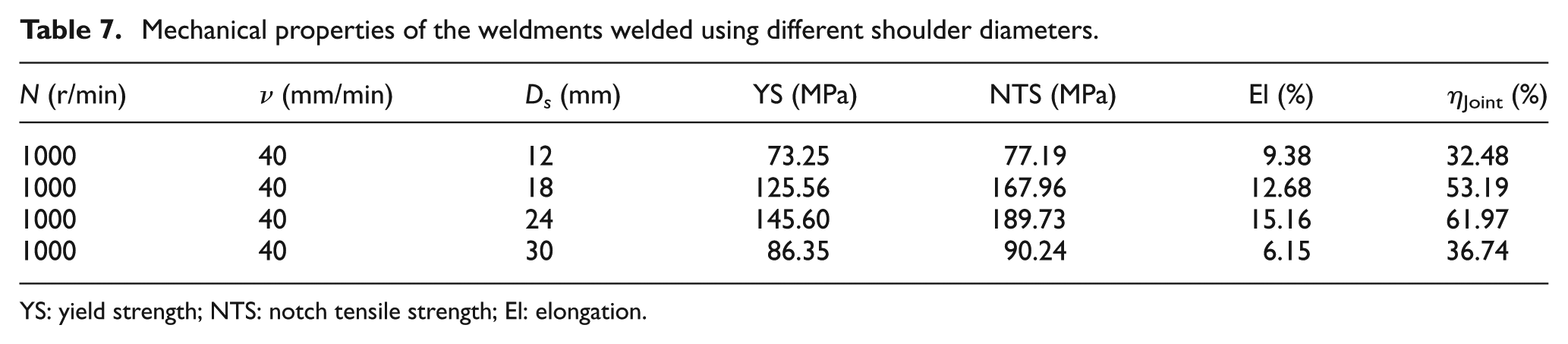
YS: yield strength; NTS: notch tensile strength; El: elongation.
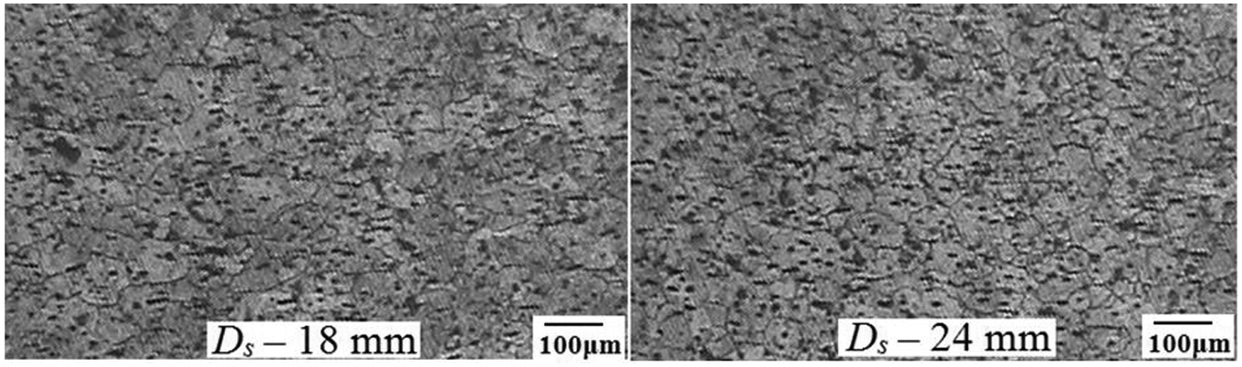
Effect of tool shoulder diameter on microstructure of FSP zone.
Effect of pin profile
The FSP region of the joint fabricated using TC pin–profiled tool contains fine equi-axed microstructure compared to other joints. The SZ of TC pin profile produces fine microstructure and in turn yields higher strength and hardness. Past researchers also reported that better mechanical properties were obtained for TC pin profile than SC pin profile. 20 –23 A SC pin profile is helpful for obtaining a smaller grain size, but nugget area obtained by SC pin profile is smaller than that by TC pin profile. For a bigger pin angle, there is a significant increase in nugget area, namely, the core of the welding where the grain size is in the order of 2–5 µm, which eventually leads to enhanced nugget integrity. 23 Ramanjaneyulu et al. 24 reported that the TMAZ width is relatively larger since a TC tool pin generates heat almost entirely by friction. The temperature generated in the case of TC pin tool is relatively lower than that in the case of SC pin tool. The microstructures of the joints fabricated using SC pin profile and TC pin profile are shown in Figure 6.
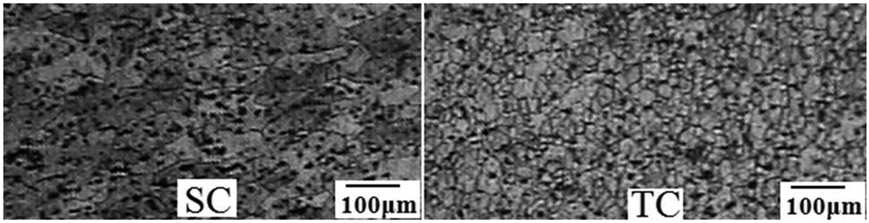
Microstructures of different pin profiles.
The primary function of the non-consumable rotating tool pin is to stir the plasticized metal and move the same behind it to have good joint. Pin profile plays a crucial role in material flow and in turn regulates the weld speed of the FSW process. Pin profiles with SC pin profile and TC pin profile were used to find the weld strength. Table 8 shows the macrostructures observed for the two pin profiles selected, and different values for size of FSP zones are for top, middle and bottom layers. The mechanical properties of the joints welded using these profiles are shown in Table 9. TC pin profile produced weld strength of 149.73 MPa as compared to weld strength of 60.61 MPa produced with SC profile. The joints fabricated by SC pin–profiled tool exhibited inferior tensile properties compared to their counterparts, irrespective of tool shoulder diameter. The relationship between the dynamic and static volumes decides the path for the flow of plasticized material from the leading edge to the trailing edge of the rotating tool; this ratio is equal to 1 for SC and 1.09 for TC profile. There is no pulsating action during stirring action in the case of SC and TC pin profiles. 1 Kumar and Suvarna Raju 25 reported that dynamic-to-static volume ratio and pulsating stirring action of pin affect the mechanical properties of FSWed joints.
Effect of pin profile on macrostructure of the weldments (N: 1400 r/min, ν: 25 mm/min, Ds : 24 mm).
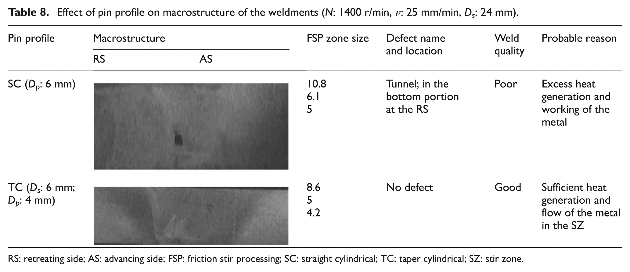
RS: retreating side; AS: advancing side; FSP: friction stir processing; SC: straight cylindrical; TC: taper cylindrical; SZ: stir zone.
Mechanical properties of the weldments for different pin profiles.
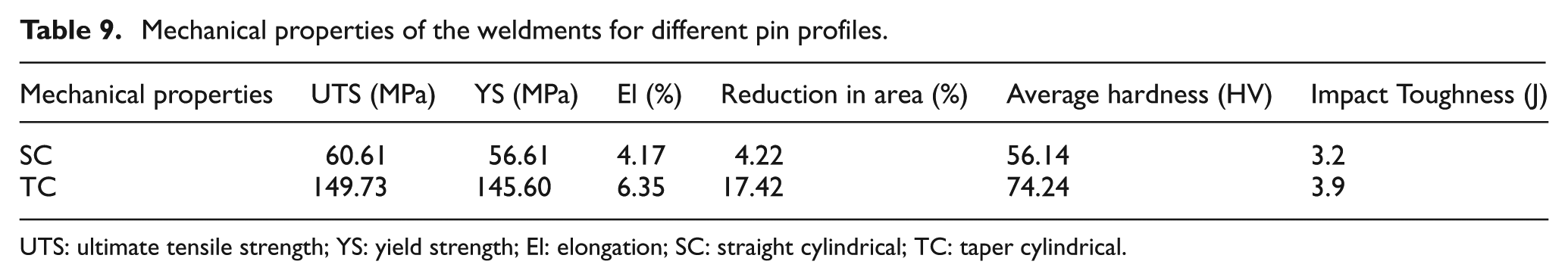
UTS: ultimate tensile strength; YS: yield strength; El: elongation; SC: straight cylindrical; TC: taper cylindrical.
Effect of Ds/Dp ratio
Table 10 depicts that the FSWed joints with tools with shoulder diameter of 18 mm (Ds/Dp = 3) have shown higher TS and elongation compared to other joints. In addition, the joints fabricated by the tools with shoulder diameter of 24 mm (Ds/Dp = 3) show superior tensile properties compared to other joints, irrespective of tool pin profiles. If the diameter of the pin is larger (Dp > 6 mm), it generates more heat and forms intermetallic compounds FeAl3 and Fe2Al5 instead of FeAl formed at low temperature. Aluminium-rich FeAl3 and Fe2Al5 are hard and brittle than FeAl and not uniformly distributed throughout the aluminium matrix and this is the reason for reduced joint strength when the ratio is greater than 3.
Mechanical properties for different Ds/Dp ratios.
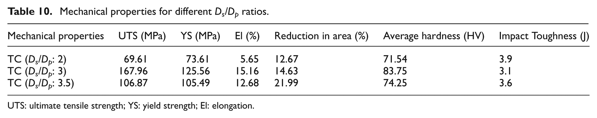
UTS: ultimate tensile strength; YS: yield strength; El: elongation.
Fracture locations of the joints
The fracture location is expressed by the distance between the fracture surface and the weld centre, and the distance is marked as a minus when the fracture occurs on the RS of the weld. 26
With regard to AA6061-T6, all the joints are fractured on the RS. Some fracture locations are distant from the weld centre and the fracture surfaces are inclined to a certain degree to the bottom surfaces of the joints, while other fracture locations are near to the weld centre. When the joints are defects free, the fracture locations of the AA6061-T6 joints are in the TMAZ on the RS, and the fracture surfaces are inclined to a certain degree to the bottom surfaces of the joints. Scanning electron microscopy (SEM) fractographs of fractured tensile specimens under 1000 r/min, 40 mm/min, TC pin profile, shoulder diameter 24 mm and shoulder-to-pin diameter ratio 3 are shown in Figure 7. The BM exhibits elongated dimples and FSWed joint exhibits finer dimples on the fractured surface (Figure 7(a)). Micrographs also reveal smaller dimple-like structure, which confirms the ductile mode failure of the joints (Figure 7(b) and (c)). The shear flow of material observed in the micrographs is the mechanism behind the failure of joint, which clearly indicates that the joints fail in a brittle manner (Figure 7(d)).
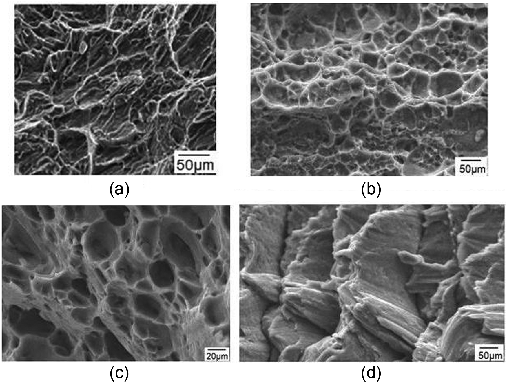
SEM fractographs of fractured tensile specimens: (a) BM, (b) FSWed fractured surface, (c) FSWed fractured surface and (d) striations at fractured surface.
At the other end of the scale, excessively high heat input may be detrimental to the final properties of the weld. Theoretically, this could even result in defects due to the liquation of low melting point phases (similar to liquation cracking in fusion welds). These competing demands lead onto the concept of a ‘processing window’: the range of processing parameters that will produce a good quality weld. Within this window (Figure 8), the resulting weld will have a sufficiently high heat input to ensure adequate material plasticity but not so high that the weld properties are excessively reduced.
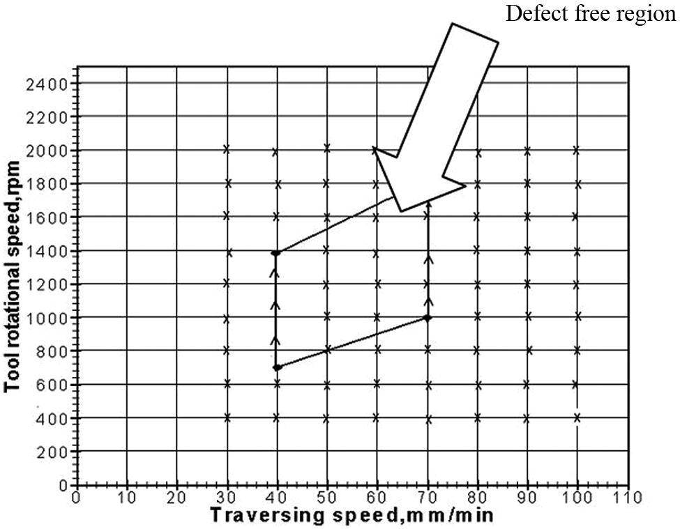
Friction stir welding window (FSWW).
Conclusion
In this investigation, an attempt was made to understand the effect of tool rotational speed, weld speed, tool geometry and Ds/Dp ratio on the formation of FSP zone in AA6061-T6 heat-treatable wrought Al-Mg-Si alloy and to develop the FSWW. From this investigation, the following important conclusions were derived.
Out of the four rotational speeds and three weld speeds, the rotational speeds of 710, 1000, 1400 r/min and weld speed of 40 mm/min produced defect-free weldments.
Out of the two tool profiles used (SC and TC), TC profile produced fine-grain structure.
Out of the four shoulder diameters used, shoulder diameter 24 mm has shown better mechanical properties compared to its counterparts.
Out of the three Ds/Dp ratios (2, 3 and 3.5) used, Ds/Dp = 3 has shown better mechanical properties and fine-grain structure compared to its counterparts.
The developed welding window will be used as ready reckoner to select appropriate rotational and welding speed to fabricate defect-free joints.
Footnotes
Acknowledgements
The authors would like to thank Dr V.K. Jain, IIT Kanpur for considering this article for the Journal. Also, sincere gratitude towards Dr B. Bhattacharya, Jadavpur University, Kolkata (Organizing Secretary, AIMTDR 2012) for reproducing this article in a revised form. The authors would also like to thank the authorities of National Institute of Technology (NIT), Warangal, India, for providing the facilities to carry out this work. One of the authors (VS Gadakh) expresses his gratitude to the management of Amrutvahini College of Engineering, Sangamner, for their support in carrying out this work. In addition, the authors would like to express their gratitude to the anonymous referees for their valuable comments and suggestions that contributed significantly to improve the quality of this article.
Declaration of conflicting interests
The authors declare that there is no conflict of interest.
Funding
This research received no specific grant from any funding agency in the public, commercial or not-for-profit sectors.