
Abstract
Pulse-width modulation rectifier plays an important role in the field of electric energy conversion. It has many advantages such as the grid side current sinusoidal, bidirectional energy flow, and unit power factor. In order to improve the power factor, this article proposes a new control method for the three-phase pulse-width modulation rectifier, that is, direct power control strategy based on virtual flux orientation. The original concept of AC motor stator flux is introduced into the proposed scheme for the three-phase pulse-width modulation rectifier so as to remove the grid voltage sampling circuit. The instantaneous power is estimated by the virtual flux vector orientation to realize the pulse-width modulation rectifier control in unbalanced condition. The two-order filter replaces the pure integrator in this process of implementation to solve the initial value problem of this pure integrator and achieve the better filtering property. With the estimation of virtual flux, the control strategy with space vector modulation realizes the fixed switching frequency to virtual flux orientation direct power control system, where the DC side output voltage is stable, the grid side current distortion rate is low, and anti-disturbance ability is strong. Experimental results show that this method has good performance in real three-phase grid condition. The control performance meets the requirements of power quality.
Keywords
Introduction
Parameters of the running AC motor are vulnerable to the influences coming from inner or outer conditions. The variables of the motor temperature and slip frequency affect rotor resistance. It may rise temperature by 50% in a short time if the rotor current is in high frequency. These parameters, such as rotor time constant, caused by these changes may lead to the distortion of feedback signal, which is calculated by fixed parameters. Based on such feedback, the flux orientation will deviate from the real one, and cause large speed and torque pulsation, that leads to the control performance decrease significantly. Therefore, for the running of variable-frequency drive system, it needs to adjust the motor parameters with its change to ensure the rightness of the feedback and the control performance. In addition, the working condition and vibration noise also affect the setting of operation parameters of the AC motor.1,2
The recent research of power electronic technology shows two shortcomings, on one hand, it brings the harmonic problem; on the other hand, the power electronic devices provide the solution for the harmonic elimination problem. 3 Pulse-width modulation (PWM) technology in inverter circuit is applied in full controlled devices to compose the rectifier circuit, which realizes the grid side current sinusoidal, unit power factor, and bidirectional energy flow.4–11 This is called PWM rectifier that achieves the green power conversion. With PWM modulation, the rectifier can greatly improve the grid content; and its filter inductor ensures the system runs at any angle with the unit power factor. From 1980s, the academia has never stopped the study of PWM converter. Along with the deepening of research, the development of PWM rectifier topology and control, its related application and researches have been in development, such as an active filter, AC drive, superconducting magnetic energy storage, high-voltage direct current transmission, and unified power flow control, which promotes the development of PWM rectifier and its control methods. A conventional three-phase voltage PWM rectifier involves four types of sensors: AC voltage sensors, AC current sensors, DC voltages sensors, and DC current sensors. They play very important roles in direct power control (DPC) on PWM rectifier,12–17 except that they are used in protective circuit. In the common control system, the AC voltage sensors detect the three-phase grind voltage amplitude, which is also used to calculate the instantaneous power of the converter. At the same time, the AC voltage sensors detect the synthetic vector rotation angle of grid voltage by phase locked loop to constitute the synchronous signal source. While the AC current sensors are used to detect the AC current value and estimate the instantaneous power with grid voltage amplitude, which constitute the inner loop feedback signal. The DC voltage sensor detects the DC voltage value to constitute the outer loop feedback signal, while the DC current sensor acts as the feed forward of load in system to enhance the performance of load anti-disturbance. However, the sensors are not essential. More sensors not only increase the cost of the system but also greatly reduce the reliability of the system. Therefore, it is necessary to study the control methods of decreasing parts of sensors.
T Noguchi et al. 12 proposed PWM rectifier control strategy without grid electric potential sensor, which simplified the signal detection of voltage source. J-H Youm and B-H Kwon 18 proposed two solutions to reconstruct the power electromotive force: the one is to estimate mathematical model of the complex power electromotive force; the other is to reconstruct it based on the proportional–integral (PI) regulation of the current deviation. The former is the open-loop algorithm, which is not high accuracy and is introduced interference in the estimation of complex power. The latter is the closed-loop algorithm, which is based on PI regulation of the current deviation to error of electromotive force in power grid reconstruction and has the high accuracy.
The control strategy without grid voltage sensors not only detects the grid voltage values, but also the grid voltage that is not needed to be rebuilt in control system. The control method depends on the grid voltage value for calculation. 19 The virtual flux method is introduced to meet the requirement of the control system. The input voltage of AC side in three-phase rectifier may produce the harmonic and unbalance conditions. 20 The phase locked is inaccurate. At the same time, the power estimation should introduce the AC harmonic component that affects the control system and grid current. Usually, the filter can deal with this harmonic component, but in the DPC system with hysteresis comparator, due to the high real time, it is difficult for the time constant of this filter to meet the demands of real-time control and harmonic component filter at same time.21,22 Additionally, since there are differences and temperature drift in sampling setting circuits, even if the three-phase grid is in ideal condition, the negative sequence component may be brought by the sampling circuits. The stator flux, defined as virtual flux, is introduced into the three-phase PWM rectifier in this article. With the virtual flux oriented vector control and estimation of instantaneous power, the DPC strategy without grid voltage sensors is obtained. The virtual flux DPC system and the space vector modulation are combined, and the combined control strategy is proposed. With the practice and experiment, the design method is discussed.
The estimation for the virtual flux of PWM rectifier
For the three-phase PWM rectifier, voltage of AC side is affected by the grid voltage and the energy of AC side inductance, which is equivalent to be an AC motor. 23 The schematic diagram of the equivalent three-phase PWM rectifier and AC motor is shown in Figure 1, in which R and L are the stator resistance and leakage inductance of the virtual motor. The grid voltage can be seen as obtained by the virtual air gap flux induction. The grid voltage vector is integrated transformation to obtain the virtual air gap flux vector.

Schematic diagram of the equivalent three-phase PWM rectifier and AC motor.
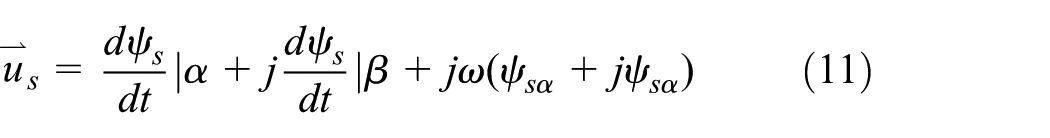
The relationship between voltage vectors in three-phase static coordinate system is as follows

where
Similarly, the relationship between the virtual fluxes is obtained by

where
In the static
where
The transform equation of a-b-c coordinate to

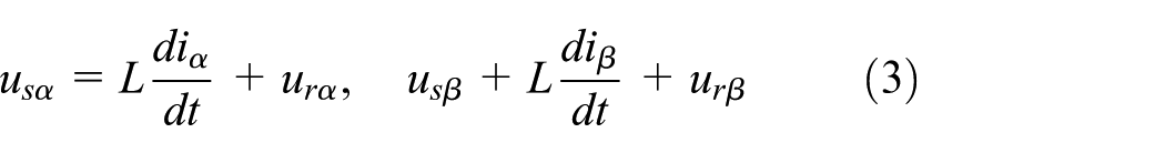
Voltage integral is flux, which can be expressed by the following equation
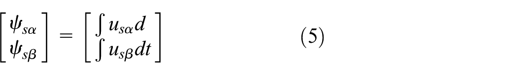

From equations (5) and (6), the virtual flux is estimated according to the DC side voltage and the chosen space vector information.
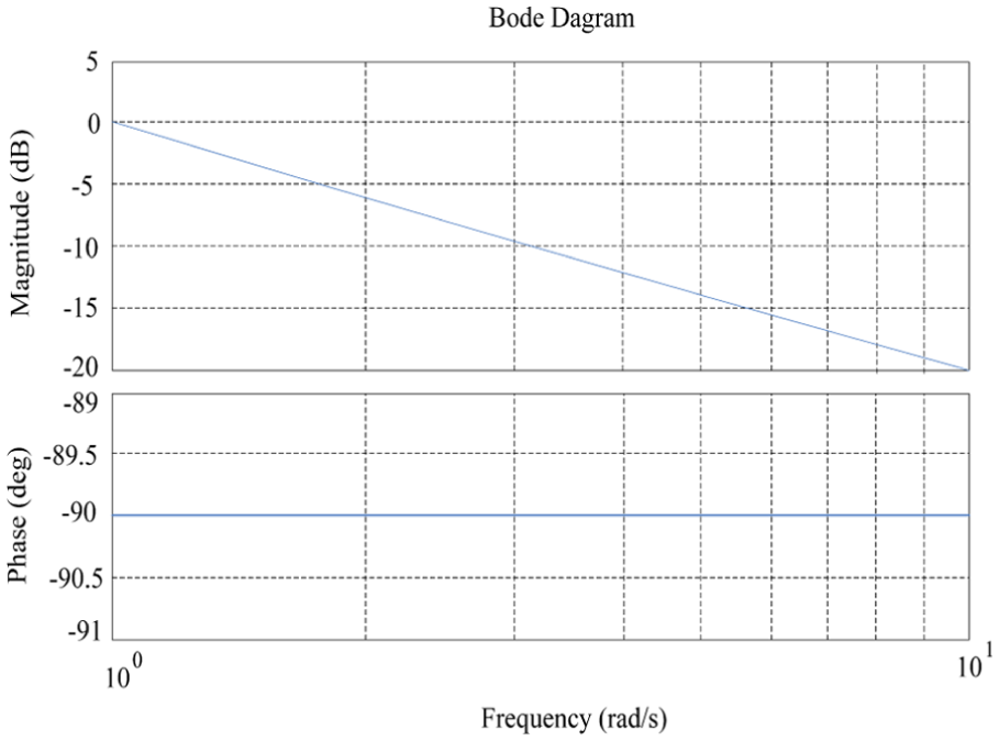
Pure integrator frequency curve.
From Figure 2, it is seen that the amplitude frequency curve is a straight line through the origin of coordinates, whose slope is every 10 times −20 dB. The pure integral has the attenuation for all AC signals whose angular frequency is bigger than 1, except that the angular frequency of this signal is 1. Assuming that an AC signal’s amplitude is A1, its angular frequency is
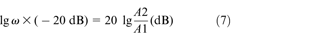
After simplified, A2 = A1/ω, let ζ = A2/A1 be the attenuation coefficient, which is the reciprocal of angular frequency

PWM rectifier virtual flux oriented vector diagram.
The calculation of instantaneous power based on virtual flux
According to the definition of complex power, the instantaneous power exchanged between converter and grid is obtained by virtual flux value and AC current sampling value. The three voltage vectors in AC side have the relationships

From the theory of the instantaneous power, the instantaneous active power and reactive power are the real part and the imaginary part of complex power, respectively. Their equation is as

where
The estimation of the virtual flux is used to estimate the grid voltage value. That is as follows

The estimation voltage vector is projected to two-phase static coordinate system, and the formula is as follows
where

Equations (8), (9), and (11) are combined to calculate the instantaneous active power and reactive power

In the ideal grid conditions, the amplitude of the virtual flux vector does not change basically and its integral approximate to zero. Therefore, the instantaneous power under ideal grid conditions is as follows

The principle of the DPC in three-phase voltage PWM rectifier
From the view of energy, in certain AC voltage, if the instantaneous power is controlled in the permitted scope, the instantaneous current is controlled indirectly in permitted scope, which is the DPC strategy. There are several remarkable characteristics in PWM rectifier with DPC: (1) by choosing the optimal switch state to control the active and reactive power directly; (2) eliminating the grid side voltage sensors, not for the measurement of AC voltage; (3) the control system does not contain the current and voltage regulator; and (4) by AC current, DC voltage, and the switch devices’ state to estimate active and reactive power.
With the control of the instantaneous power, DPC method controls the instantaneous current, makes the grid side current sinusoidal, and achieves unity power factor. Compared with the conventional current control strategy, it has the advantages of high power factor, low total harmonic distortion (THD), high efficiency, and simple algorithm and program. The circuit construction of the traditional voltage source DPC is shown in Figure 4. The vector space is divided into 12 sectors in DPC rectifier system, as shown in Figure 5.

Diagram of the traditional direct power control.

The graph partitioning and voltage space vector.
The rectifier bridge is composed of six switch tubes, and the two tubes in the same bridge arm can only pass complementary. There are eight kinds of switch states. They are represented by
The rectifier voltage space vector table.

From Figure 5, the voltage source reference voltage vector is as follows


DPC also needs to be prepared in a switching table, in which the appropriate switch state can be chosen during the system working. Table 2 is the switching table used in the traditional DPC system. The above is the principle of the traditional DPC and its realization method. Hysteresis loop width and switching table determine the control performance. It can be seen from Table 2 that if the reference voltage vector is in the even number sector, the instantaneous active power error signal
Traditional direct power control system adopts the switch state.

Design and realization of DPC system based on virtual flux
The construction of DPC system based on virtual flux
According to analysis and inference in front, we can carry out the orientation and power estimation using virtual flux. However, there are some technical problems in the process of implementation of system design, such as the integral initial value, which will directly affect the control features.
A DPC system based on virtual flux, shown in Figure 6, is different from the traditional DPC system. In this new system, the grid voltage sampling circuit is removed, and virtual flux (VF) vector estimation and phase detector replaces the grid voltage vector discriminator. The functions of power and VF estimation are divided into the following steps, as shown in Figure 7: the first step is estimated based on the DC voltage and a moment three-phase bridge arm switch function S on the AC side voltage; the second step is to calculate the VF value by the AC inductance, AC current, and AC side voltage; the third step is to estimate the instantaneous power by the VF estimation and AC current sampling value; and finally the estimation is put into controller. This system is a double-loop system based on hysteresis comparator.
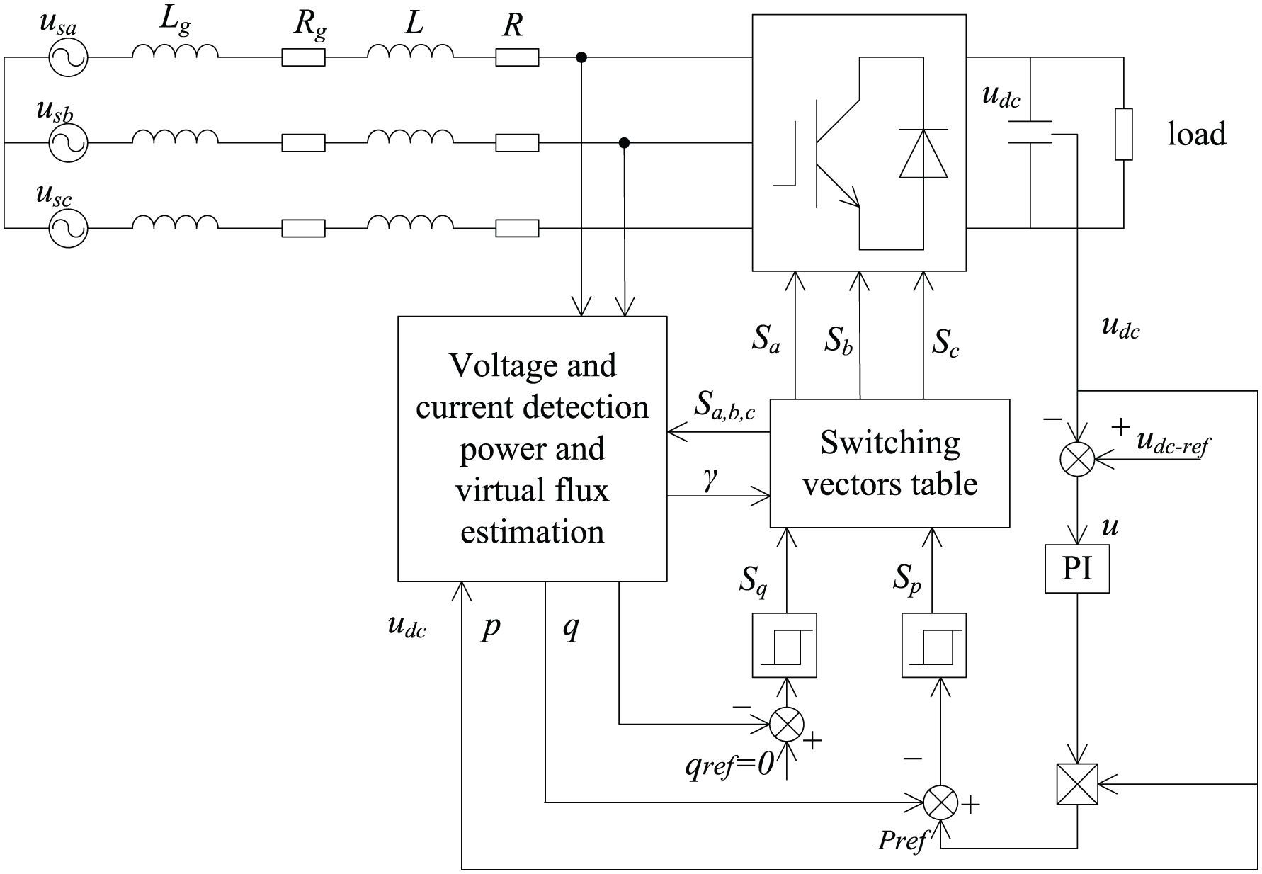
The DPC system based on virtual flux.

Power estimation and virtual flux.
This system can get good control performance in the condition of non-ideal power grid. This is because the VF produces the integral role. The non-ideal grid is divided into two types: one is three-phase symmetrical grid, each phase voltage contains the same harmonic amplitude; another is that the sine degrees of the three-phase grid voltages are good but the voltage amplitudes are different. One or all of the types may occur in grid. We will analyze the difference between the orientation of grid voltage vector and VF vector in these two types of grid conditions. In the traditional DPC system orientated by grid voltage vector angular, when the grid voltage contains harmonic components, the estimation of power has been affected. This leads to the harmonic introduced to calculation of the instantaneous power, the operation of hysteresis comparator has been affected, and this harmonic is involved in AC current. Another serious situation is caused by the out of phase of fundamental harmonics of grid voltage, which results in the error in phase locked loop (PLL). The sector judgment of grid voltage vector has been affected directly, so as to occur the mistake in switch vector choice and not to control the power. When the grid voltage is unbalanced, the negative sequence of fundamental voltage disturbs the estimation of the instantaneous power, and even the negative sequence current is occurred. 24 The safe operation of converter is brought a threat. In DPC system based on VF, the grid voltage angular is changed to the vector angular of VF. Because the flux is the integral of grid voltage, and the integrator has the feature of the low-pass filter, the multiple attenuation of harmonic voltage amplitude will be larger K times than that of fundamental (K is the harmonic number). Therefore, the orientation with VF vector not only cancels the grid voltage sensors but also overcomes the zero-offset problem caused by harmonic voltage, so as to ensure the accuracy of oriental angle. In the unbalance phenomenon of the grid voltage fundamental, there are two times of harmonic voltage in converter DC side. This low order harmonics can be removed by power estimation with VF.
The two-order replacement of the integral value problem
From the integral definition, if the function

It is seen that the time

where

Realization method of pure integral in discrete space.
The pure integral cannot eliminate the DC component. If the initial value has error, the output will always contain the DC component with the same error as initial value. Therefore, it is difficult to use the integral to estimate VF value if its initial value is not known. Otherwise, a DC bias with related integral initial value will be introduced to the VF estimation. This results in that the flux trajectory is a circle in

When the three-phase bridge put out the zero voltage vector,
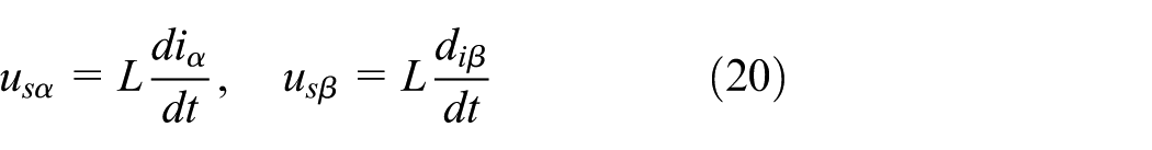
Equation (20) is put into equation (19), then
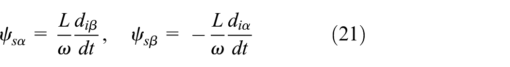
Several zero voltage vectors, whose duration is T, are added before PWM rectifier operation. The virtual grid flux is observed by current amount and equation (21), in order to obtain the initial value of VF. Because no switching is in the process of this operation and the circuit is linear, the current noise is little and the initial value of VF is obtained accurately. However, this method omits the effects on AC impedance of R. When the zero vectors are applied, the converter is equivalent to a grid line inductance of AC voltage side and direct short circuit. Since the instantaneous current is very large, the estimation accuracy has been affected if the obvious AC impedance voltage drop is ignored. The similar problems are in the direct torque control to AC motors. When the stator side flux is estimated, the pure integral method is simple. The parameter related to the motor parameter is stator resistance, which is easier to determine. But it is easy of the pure integral to be affected by the input signal DC bias to be saturated, the low pass filter,

One-order inertial link instead of pure integrator eliminated the DC component.
The pure integrator replacement to the two-order link is presented in this article, which is better equivalent of pure integrator in fundamental frequency. From observation, the inertia link’s gain at the cutoff frequency is −3 dB and its phase lags


VF-DPC can get better control performance in the unideal grid condition. At the same time, there are also the inherent disadvantages with the usage of hysteresis comparator and DPC system:
The switching frequency is not fixed so that the design of input filter has more difficulty;
The switch polarity is not coherent and the switching stress is big;
The hysteresis controllers need the higher sampling frequency in digital control system;
The digital processor and analogue-to-digital (AD) chip are needed the higher speed in this system.
Therefore, the application of VF-DPC has a distance to industrial field. However, the space vector modular instead of switching table can eliminate these disadvantages after the transformation of the modulation. The idea of DPC based on space vector modulation is introduced to VF-DPC, in which space voltage pulse-width modulation (SVPWM) and PI regulator are used to accomplish the fixed switching frequency control. The difference between the two methods is due to orientation. VF vector angle

where

The control system construction of VF-DPC-SVM is shown in Figure 10, which not only contains the advantage of VF method but also has the stress on space voltage modulation (SVM) modulation with fixed frequency after the improvement. It is a very ideal DPC system.

The VF-DPC-SVM control system structure diagram.
Simulation and experimental results analysis
Simulation platform and results
Simulation of the traditional DPC system for PWM rectifier
The traditional DPC strategy for PWM rectifier is simulated using MATLAB/Simulink to build simulation platform. Setting the parameters as follows: line voltage effective value is 380 V, the grid frequency
Figure 11 is a simulation platform model built using MATLAB/Simulink, which uses the traditional voltage oriented DPC. Three phase voltage and current are sampled directly from the network side through the sensor, and the switch tube is made of insulated gate bipolar transistor (IGBT) with anti-paralleled diode. The simulation results are shown in Figure 12.

Simulink of the traditional direct power control for PWM rectifier with L filter.

Simulation results of traditional direct power control for PWM rectifier: (a) output DC waveform of voltage, (b) output DC waveform of current, (c) current and voltage of A-phase on grid side, and (d) current harmonic spectrum of A-phase on grid side.
Figure 12(a) shows the output DC voltage waveform of the traditional three-phase voltage PWM rectifier, we can see that the voltage is stable at 700 V after 0.05 s, dynamic performance is better, overshoot within 5%. Figure 12(b) shows the output DC current waveform of the traditional three-phase voltage PWM rectifier. It can be seen that the current follows the voltage very well. After 0.05 s, the current is stable at 7 A, and the dynamic performance is good. Figure 12(c) is the waveform of the phase A current and voltage at the grid side. It can be seen that the stable current waveform basically presents a sine wave, but the current harmonic content is very large. Figure 12(d) is the PWM rectifier AC side of the A-phase current and its harmonic analysis. It can be seen that the AC side current contains more harmonics, especially the low harmonic content is very high, the THD reached 32.64%. This is far beyond the International Electrical Commission of the THD of less than 5% of the standard.
Simulation of DPC system for PWM rectifier with VF
The DPC strategy for PWM rectifier with VF is simulated using MATLAB/Simulink to build simulation platform. Set the parameters as follows: the line voltage effective value is 380 V, the grid frequency is 50 Hz, the DC side capacitor is 5000 µF, load resistance is 100 Ω, DC voltage is 600 V, and switching frequency is 5000 Hz. According to the filter design rules to select suitable parameters: grid side inductance is 1 mH, internal resistance is 0.1 Ω; AC side branch filter capacitor is 16 µF; AC side of the inductor is 2 mH, and the resistance is 0.2 Ω.
The traditional DPC scheme has the disadvantages of high switching frequency and poor stability of the system, and this article proposes a DPC based on virtual flux without voltage sensor. The control system adopts the double closed-loop control structure of voltage outer loop and power inner loop. A simulation platform model has been built using MATLAB/Simulink as shown in Figure 13. The DPC for PWM rectifier with VF, PI regulator instead of the traditional hysteresis comparator, and SVPWM other than the traditional switch table, are used. The simulation results are shown in Figure 14.
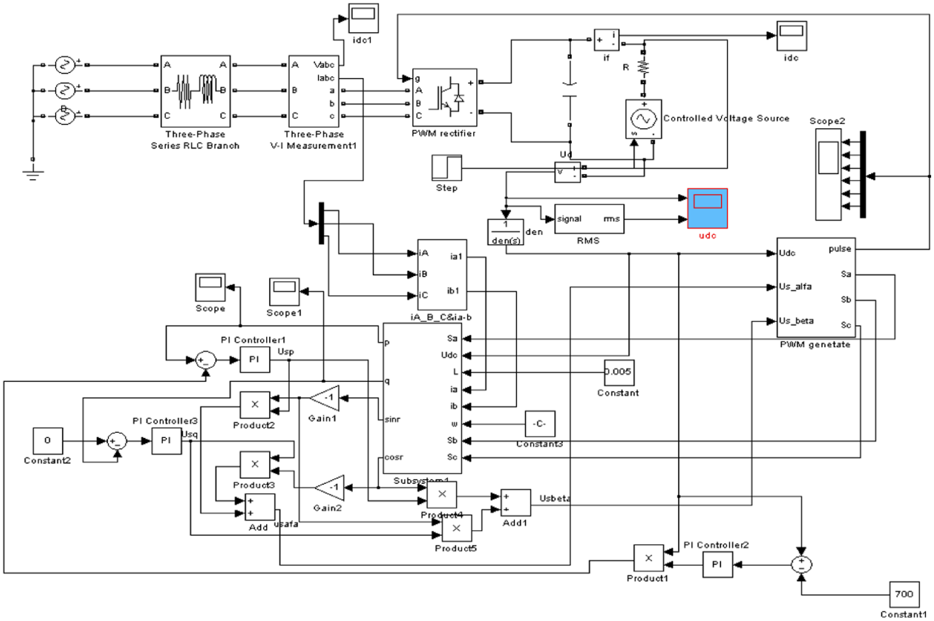
Simulink of the direct power control for PWM rectifier with VF.
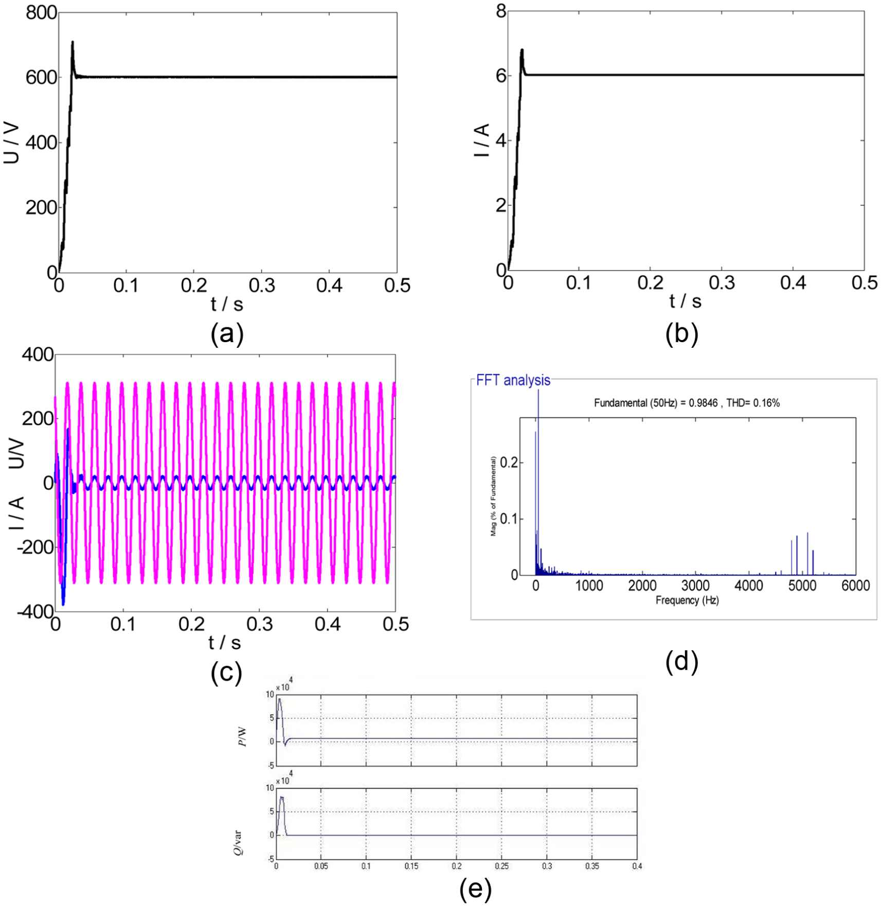
Simulation results of the direct power control for PWM rectifier with VF: (a) output DC waveform of voltage, (b) output DC waveform of current, (c) current and voltage of A-phase on grid side, (d) current harmonic spectrum of A-phase on grid side, and (e) reactive power and active power.
Figure 14(a) shows the output DC voltage waveform of the PWM rectifier with VF, we can see that the voltage is stable at 700 V after 0.02 s, dynamic performance is very good, overshoot within 5% and achieve desired control results. Figure 14(b) shows the output DC current waveform of the PWM rectifier with VF. It can be seen that the current follows the voltage very well. After 0.02 s, the current is stable at 6 A, and the dynamic performance is good and achieves desired control results. Figure 14(c) is the waveform of the phase A current and voltage at the grid side. It can be seen that the stable current waveform is a sine wave, current and voltage phase is the same, the current harmonic distortion is small. Figure 14(d) is the PWM rectifier AC side of the A-phase current and its harmonic analysis. It can be seen that the AC side current contains less harmonic, the THD is only 2.01%, near the switching frequency of 5 kHz, the high-order harmonic amplitude is less than 1%. Resonance is better suppressed, and the current harmonics of the grid side are greatly reduced, and the expected control effect is achieved. This is fully in line with the International Electrical Commission of the THD of less than 5% of the standard. Figure 14(e) is the waveform of the reactive power and active power. It can be seen that the reactive power is zero, and the control system achieves the result of unity-power factor operation. Although the presence of the filter capacitor will reduce the power factor of the control system, the power factor is still greater than 0.98.
Based on the simulation and analysis of traditional DPC strategy for PWM rectifier and DPC strategy for PWM rectifier with VF, the results show that DPC strategy for PWM rectifier with VF has better dynamic performance. Network side current harmonic is greatly reduced, and the unity-power factor control can be achieved, and a very superior control effect is achieved.
The system experiment and its results analysis
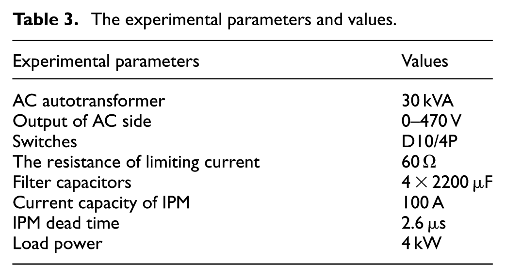
The experimental platform is established as shown in Figure 15. The experimental parameters values are shown in Table 3. The experimental parameters are AC autotransformer is 30 kVA; the output of AC side is adjustable from 0 to 470 V; the air switches select D10/4P; the resistance of limiting current is 60 Ω; filter capacitors are 4 × 2200 µF; and intelligent power model (IPM) is select as the power semiconductor with 100 A current capacity. TMS320LF2812DSP is select to control the system. Oscilloscope of Agilent-600 is used to observe the output waveforms. The experiments of hardware platform are operated, in which the rated load power is 4 kW, input voltage is 120 V, the given frequency is 50 Hz, and IPM dead time is 2.6 µs. The results are shown in Figure 16.

Experiment platform of PWM rectifier.
The experimental parameters and values.

The voltage and current waveforms: (a) DC side voltage, (b) grid side voltage and phase current, and (c) the grid side current waveform.
The output waveform of DC link voltage is shown in Figure 16(a). In Figure 16(b), grid side line voltage
Conclusion
In this article, the DPC method of three-phase PWM rectifier based on virtual flux orientation is proposed and realized, which improves the reliability of the system without the grid voltage sensors. Moreover, the proposed method runs well under the condition of non-ideal power grid. The space vector modulation method combined with DPC strategy based on virtual flux is discussed and its advantages and disadvantages are analyzed, thus it is proved a very valuable control method. Furthermore, the experiment platform of three-phase voltage source PWM rectifier is established for theoretical analysis and simulation verification. The experimental results show that the DC output voltage is stable, the AC side current distortion rate is low, the power factor is high, and it has a strong ability to resist load disturbance and can satisfy the control requirements and then verify the validity of the control scheme.
Footnotes
Acknowledgements
B.F. and Z.-X.Y. conceived and designed the experiments, L.S. performed the experiments, S.-Z.S. and X.-B.W. contributed analysis tools, and B.F. analyzed the data and wrote the paper.
Academic Editor: Chi-man Vong
Declaration of conflicting interests
The author(s) declared no potential conflicts of interest with respect to the research, authorship, and/or publication of this article.
Funding
The author(s) disclosed receipt of the following financial support for the research, authorship, and/or publication of this article: This work was supported by the National Natural Science Foundation of China (U1404512 and 61473115), the Project of Luoyang Sci. & Tech. Development Plan (1401017A), and International S&T Cooperation Program of China (ISTCP) (2016YFE0121700). This research was also supported by the University of Macau (MYRG2015-00077-FST). The funding sponsors had no role in the design of the study; in the collection, analyses, or interpretation of data; in the writing of the manuscript; and in the decision to publish the results.