
Abstract
In this paper, a double closed loop controller based on equivalent input disturbances (EID) error perturbation is proposed to solve the problem of abnormal operation of three-phase pulse width modulation (PWM) rectifier caused by load and external conditions. By analysing the buffeting problem and response time problem caused by traditional sliding mode in the current control process, a new current control method of terminal fuzzy sliding mode is designed. The system error is estimated by EID error estimation, and fuzzy control is introduced to improve the accuracy of error estimation, which solves the current buffeting and response problem. In order to solve the problem of response rate and harmonics in the voltage controller design, the extended state observer (ESO) in active disturbance rejection control (ADRC) control is improved, EID error estimation is introduced, the response rate and anti-disturbance ability of the system are further improved, and the harmonics of the system are suppressed. The experimental results show the effectiveness and superiority of the proposed method.
Keywords
Introduction
Nowadays, green low-carbon environmental protection has become a common development trend.1,2 Electricity is the most widely used energy source in both life and industrial development, so there are high requirements on the quality of electricity.3,4 For the purpose of getting high quality electricity and reduce energy losses, the electricity needs to be controlled and transformed in its production, transmission, distribution and use.5,6 The current intelligentisation of electricity grids puts forward much more high demands to performance of power electronic appliances, and the stabilisation and reliable operation of the converter, as a key device in power conversion, also need to have strict requirements.7,8 A three-phase PWM rectifier extensively applied to microgrid, 9 superconducting energy storage, 10 motor drive speed regulation, 11 and other fields with the advantages of high power factor and bi-directional energy transfer, and its stability and reliability research value is high.12,13
This paper considers a PWM rectifier as a target, analysing rectifiers underactuated properties, 14 aiming to promote power utilisation in grids and to ensure that the PWM rectifier can operate normally under load transformations and external disturbances. To these two ends, the PI control methods were designed but cannot meet the control demand well, so many advanced control methods are generated.15,16 For example, Zou et al. 17 presented a generalised Clark’s transform and enhanced dual-circuit control system. Interleaved single-phase PWM monostage resonant rectifiers featuring high voltage isolation was created by literature. 18 Interleaved Single-Stage resonant rectifiers for three-phase power PWM combined with high voltage isolation was created by literature. 19 A quasi-resonant prolonged phase observer-based predicted current regulation method was presented by literature. 20 For the single phase PWM rectifiers, the grid-voltage sensorless modelling for forecasting control was presented by literature. 21 Ashry et al. 22 development of a simplicity mould for UHF rectifiers to enable the optimisation in rectifier performances. Additionally, other nonlinear control methods have been used, such as direct power control,23,24 fuzzy self-tuning,25,26 active disturbance rejection control strategy27,28 and model predictive control,29,30 etc. For PWM rectifier, high power factor operation and fast response are essential, and to assure an effective system response to external perturbations and has high stability in the face of parameter variations, for example, voltage surges or load transformations.
In this paper, we analysed PWM rectifier’s characteristics and use its characteristics to divide the PWM rectifier system into a dual closed-loop control system with actuated subsystem and underactuated subsystem for reducing the energy usage. The actuated subsystem is a current-loop control system, which uses terminal fuzzy sliding mode control based on EID error estimation to reduce the current jitter and negative sequence current caused by conventional sliding mode, and optimises the nonlinear function in sliding mode control to improve suppression effect. Underactuated subsystem is a voltage loop control system, and the EID-based active disturbance rejection control (ADRC) strategy is designed to improve the system immunity while suppressing the harmonics in DC-side voltage. The purpose of adding EID is to diminish the current square wave jitter under ADRC control strategy. Finally, a simulation experiment platform is built on MATLAB/Simulink in order to verified the efficiency for proposed strategies this research suggests. Then simulation results shows an achievement of control objectives of PWM rectifier: (1) unit power operation of the system; (2) achieving current sinusoidalisation. Experiments validate the accuracy and superiority of the controlling method. In summary, there are three key contributions from this paper.
(1) The underactuated characteristics of PWM rectifier are analysed, and the feasibility is explained for dual closed-loop control based on its underactuated characteristics.
(2) Aiming at the current loop control method, we analyse the reasons of leading to the systems large buffeting in the traditional sliding control and the advantages and disadvantages of its control, and proposed a novel sliding control method which can reduces the current buffeting as well as improves the control effect.
(3) For the voltage loop control method, we propose an ADRC control method based on EID error estimation, which effectively solves the voltage tuning problem, and also improves the dynamics and stability properties for systems.
A structural framework of content of the paper has been organisation as follows. In Section ‘Modeling and analysis’, we explain the modeling, and carry out its characteristic analysis and feasibility analysis. In Section ‘Current loop controller design’, we propose a new controlling strategy to target the electric circuit control network. In Section ‘Voltage loop controller design’, we propose an ADRC control method based on EID error estimation for voltage loops. In Section ‘Simulation experiments’, we carry out experimental verification for different working scenarios of PWM rectifier. Finally, the work of this paper is summarised.
Modeling and analysis
Mathematical model
The principle diagram of the circuit structure of the 3-phase voltage PWM rectifier as shown in Figure 1.
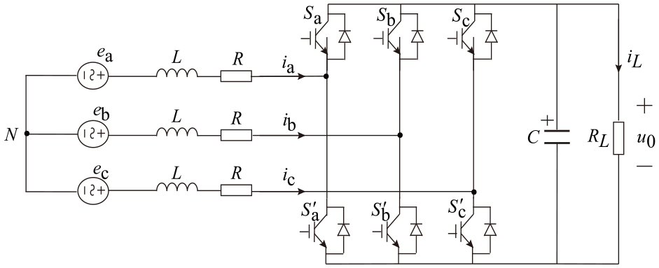
PWM rectifier circuit structure topology diagram.
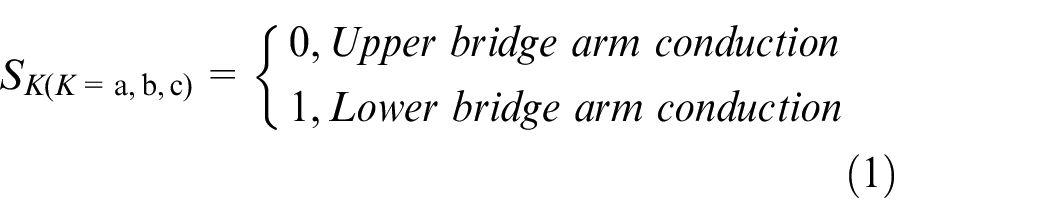
Define the switch function as shown in equation (1).
As shown in equation (2), the PWM rectifier is mathematically modelled using Kirkhoff’s voltage and current laws. 31
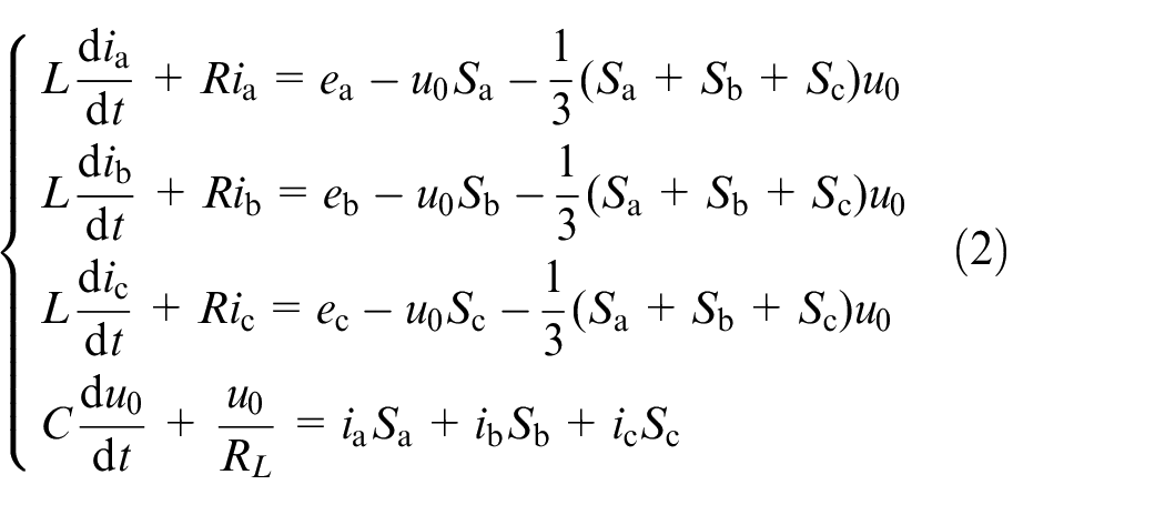
where,
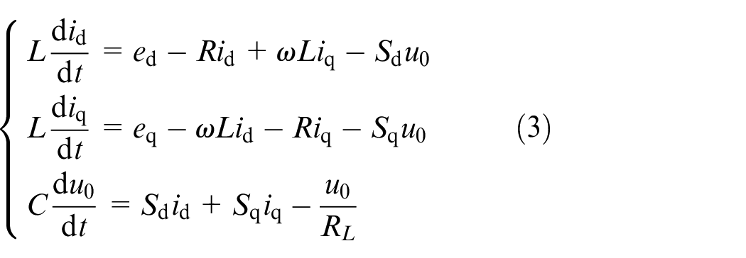
We substitute the above equation into the dq synchronous rotating coordinate system and use the equal power coordinate transform method to get the simplified mathematics mode of the PWM rectifier as shown in equation (3).
Characteristic analysis
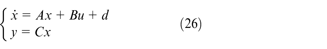
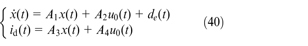
By using equation (2), a state space expression is obtained as shown in equation (4).
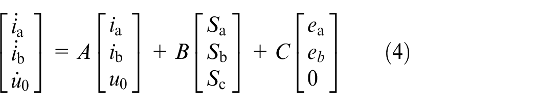
Where
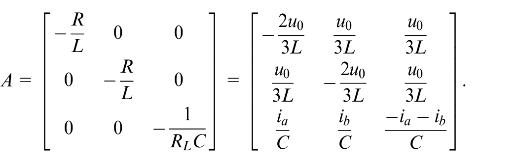
According to the state space expression described in equation (4), the coefficient matrices
Feasibility analysis
The final control strategy designed is given in Figure 2. Following this, a feasibility analysis of the above options is performed using mathematical methods. As can be seen from equation (3),
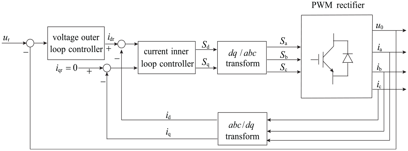
Control strategies structure diagram.
The instantaneous power balance for PWM rectifiers is expressed as equation (5) by means of an iso-power coordinate transformation.
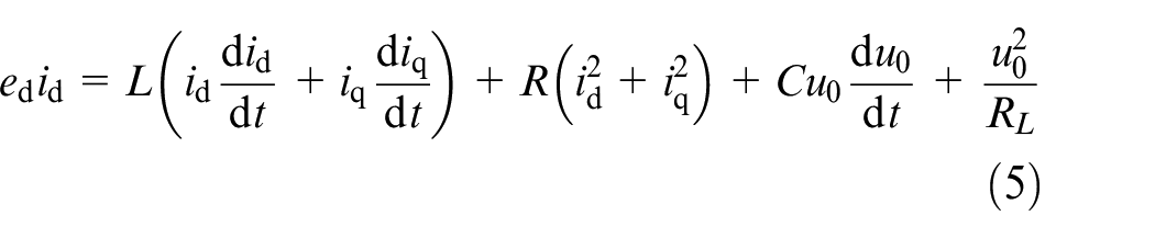
In equation (5), in order for the current loop to achieve precise control, the current needs to converge to a given value, define
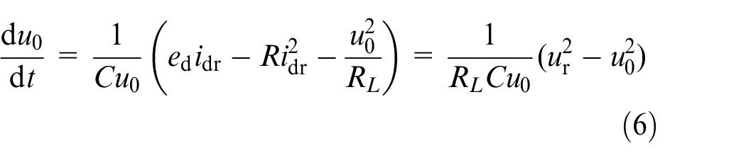
From equation (6), so that
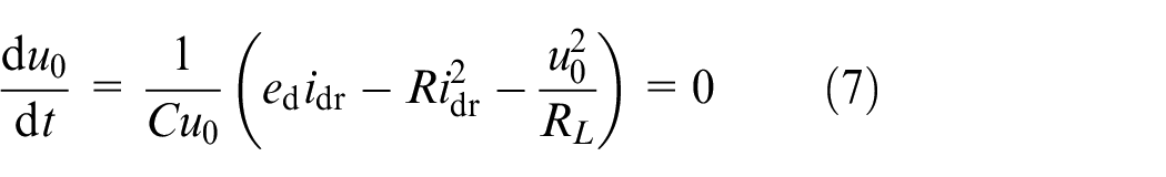
According to equation (2), the transfer function equation of
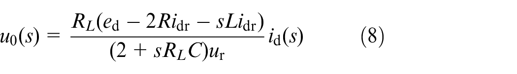
Therefore, it is theoretically only necessary that
Current loop controller design
Aiming at the design of current loop controller, the chattering problem of traditional sliding mode in the process of current control is analysed first, which is also an important problem of sliding mode control, and the reason of chattering in current control is analysed that the sliding mode gain is too large. To solve this large gain problem, we propose a terminal fuzzy sliding mode control method based on EID error estimation. The EID error estimation is used to predict the system interference, and the fuzzy control is used to improve the prediction accuracy and ensure that the designed sliding mode gain is close to the system interference, so as to reduce the current buffeting.
Conventional sliding mode control
Current loop system of control as illustrated by equation (9).
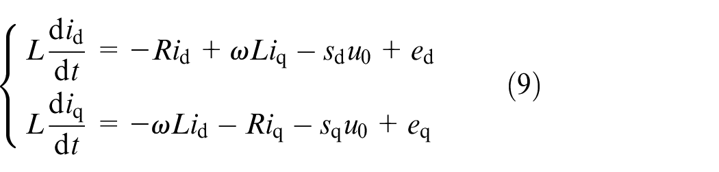
In order to better reflect the active power and reactive power of the system, two sliding mode surfaces are selected for control, and
Definition of error is:
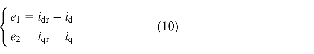
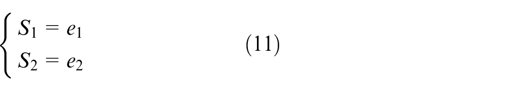
Design the sliding surface as shown in equation (11).
The isokinetic convergence rate is:
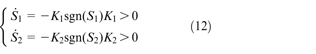
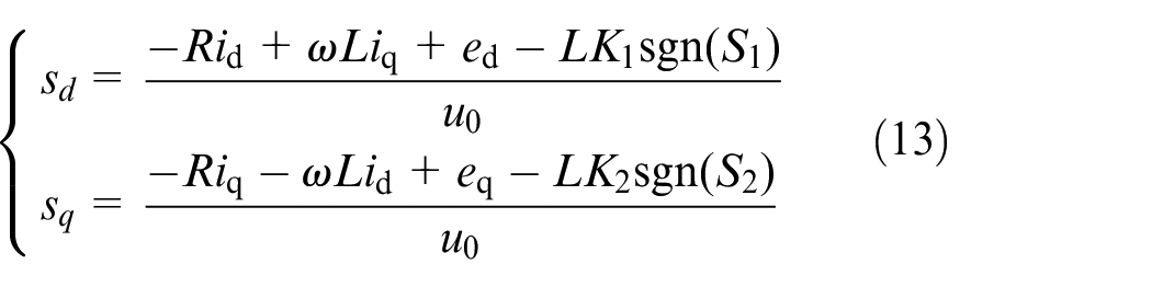
Combining equations (9) and (12) yields
When there is parameter uptake or external disturbance in the system, the current control system description changes as equation (14).
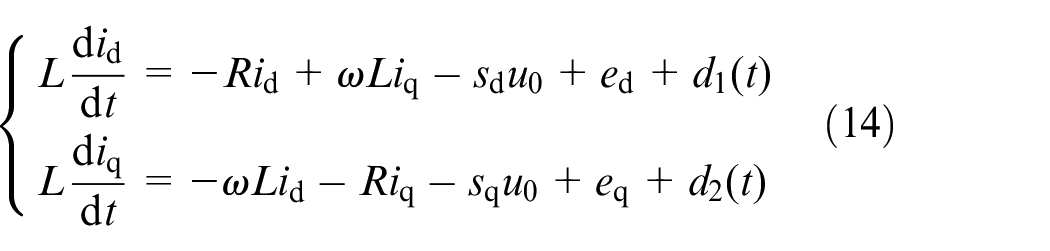
where
Bringing the control equation of equations (13) into (14), we get
To make sure that the system is stable under disturbed states, it is necessary to make the sliding mode have a stable condition, that is,
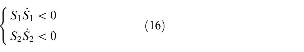
which in turn leads to
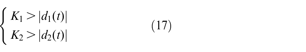
In practice, the disturbance is often unknown, so the upper bound
Terminal fuzzy sliding mode control based on EID error estimation
Design slip surface:
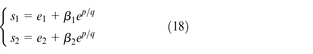
where, the errors
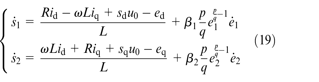
Derivation of equation (18) yields:
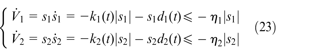
Define the Lyapunov function
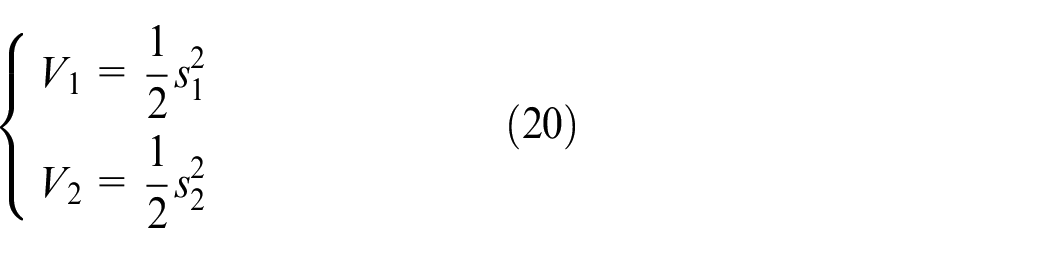
The derivative of equation (20) yields:
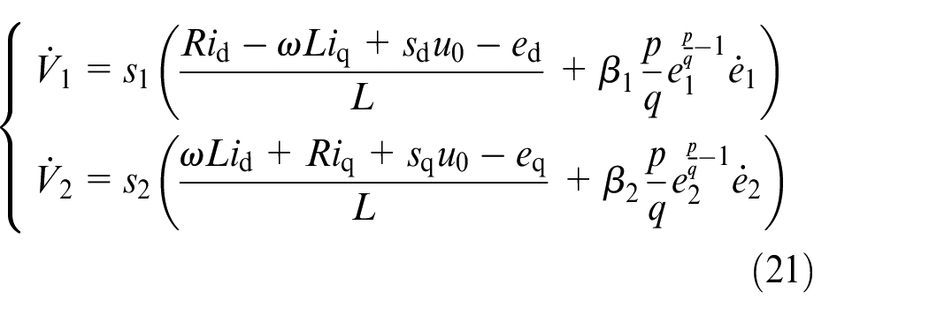
According to the system stability principle,
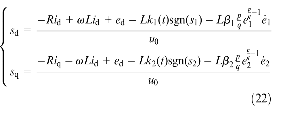
where,
Substituting equations (22) into (14) for a current system with external disturbances yields
When
In order to ensure that the system can be better stabilised under disturbances, the fuzzy control theory is used to optimize the problem that the upper bounds of disturbances
In order to make
The expression of the switching gain is shown in equation (24).
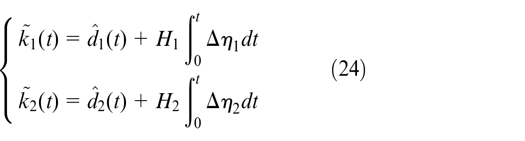
where,
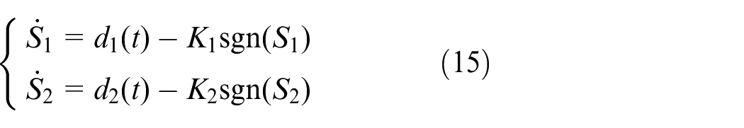
Firstly, EID error estimation is used to estimate the current system errors
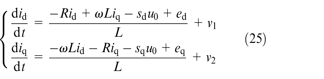
To better describe the system, let
Expressing equation (25) as
where,
Design observers as
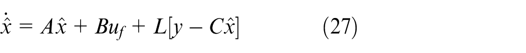
where,
According to the principle of EID error estimation described in the literature, 33 the interference estimate is obtained
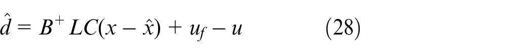
Where
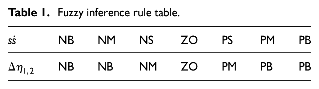
Second, the following fuzzy system is designed using


When
Fuzzy inference rule table.
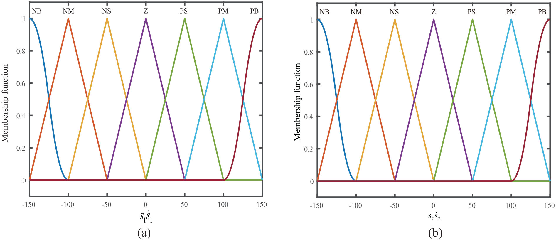
Membership function corresponding to fuzzy input
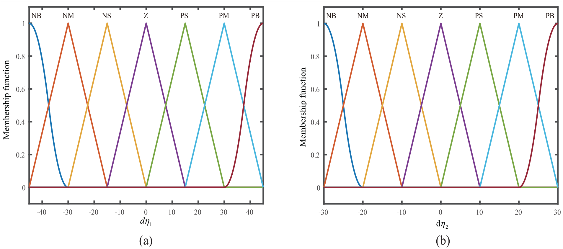
Membership function corresponding to fuzzy input
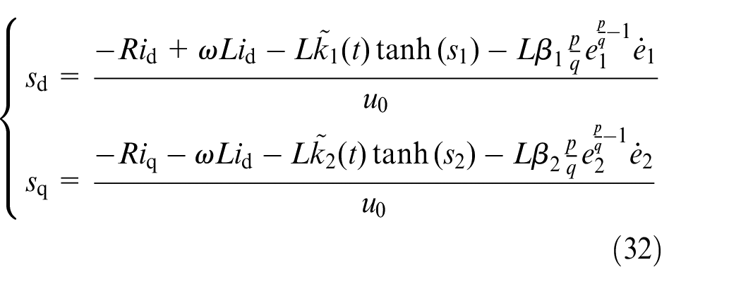
The main part of the current return controller has been designed. Meanwhile, to solving the problem that sign functions are not continuous in zero point or not smooth at transition points, We use hyperbolic tangent function instead of sign function. The mathematical expression is shown in equation (31).

where,
The controller finally gets as shown in equation (32)
Voltage loop controller design
For the design of voltage loop controller, the problems that may occur in the process of voltage control by the active disturbance rejection control method are analysed, that is, the response rate of the system voltage and the harmonics of the system. To solve this problem, an active disturbance rejection control method based on EID error estimation is proposed. Based on the traditional active disturbance rejection algorithm, ESO is optimised and EID error estimation is introduced. Improve the response rate of the system and anti-harmonic problems.
Conventional ADRC
ADRC has been proposed as one of the nonlinear control methods for nonlinear uncertain systems, as shown in Figure 5.
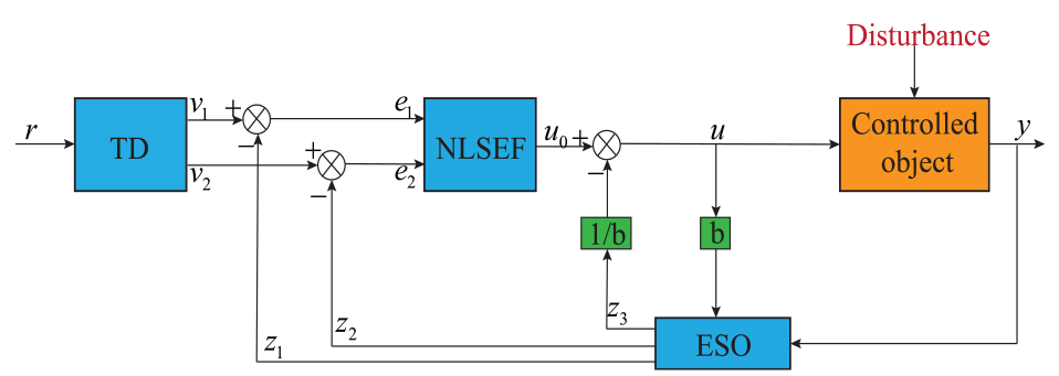
Structure diagram of ADRC.
TD can arrange a reasonable transition process according to the bearing capacity of the controlled object, which can reduce the overshoot while ensuring the rapidity. The unmodeled dynamic and unknown internal and external disturbances are summarized into total disturbances by the ESO, which is estimated and compensated, so that the key to the design the controller does not consist in deriving an accurate mathematical model of the object or disturbance. Meanwhile, a compensation effect can realise the system without static adjustment. NLSEF control law uses nonlinear structure to suppress system error and improve system control performance.
A general nonlinear uncertainty system could denoted as

where
Based on the nonlinear uncertainty system, the following ADRC controller is designed.
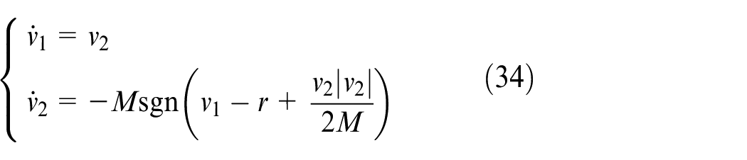
(1) tracking differentiator
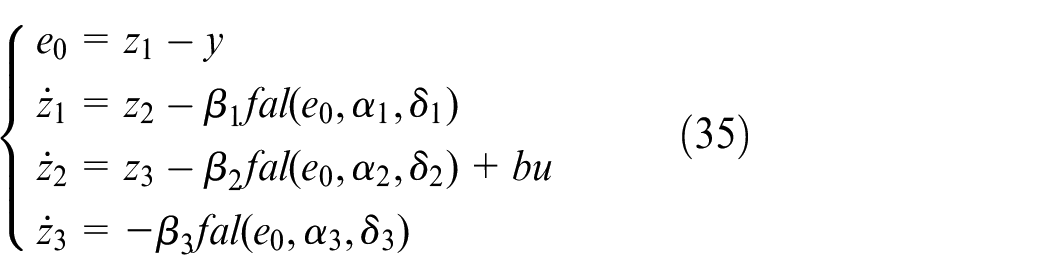
(2) extended state observer
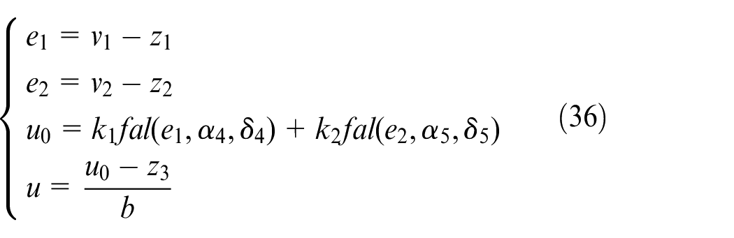
(3) nonlinear state error feedback
where,
Let
According to equation (33), setting
Design ADRC controller according to equation (38) as
However, under this ADRC action,
EID/ADRC control
In response to the analysis discussed earlier, an ADRC/EID error estimation is proposed to optimise the fluctuation of the current
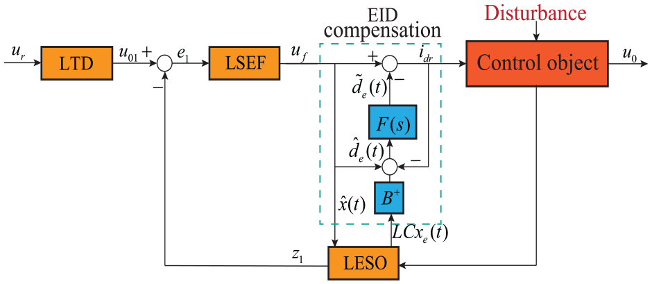
EID/ADRC controller.
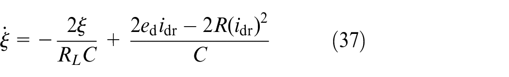
According to equation (38), an error
Based on transfer function relations among
where,
Design of state observer for equation (40) is
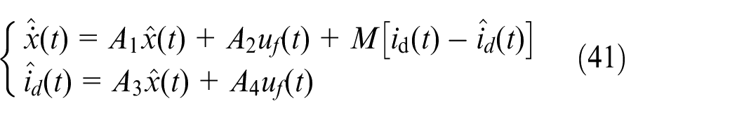
where
A definitive estimation for
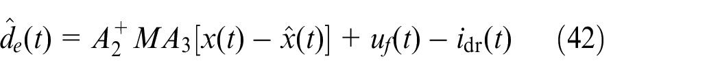
where,
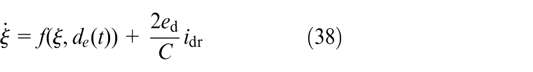
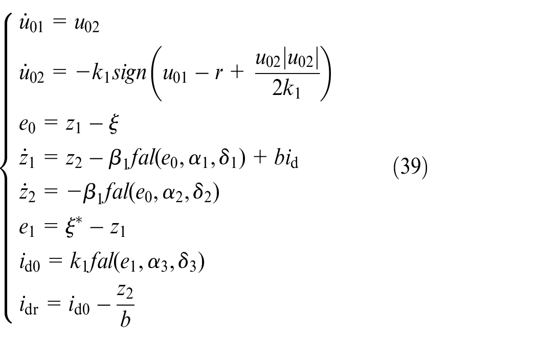
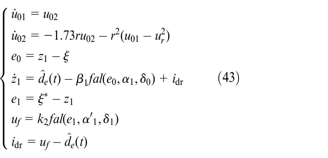
For the first-order voltage control system, the EID/ADRC controller based on equations (42) and (39) is designed as shown in equation (43).
Simulation experiments
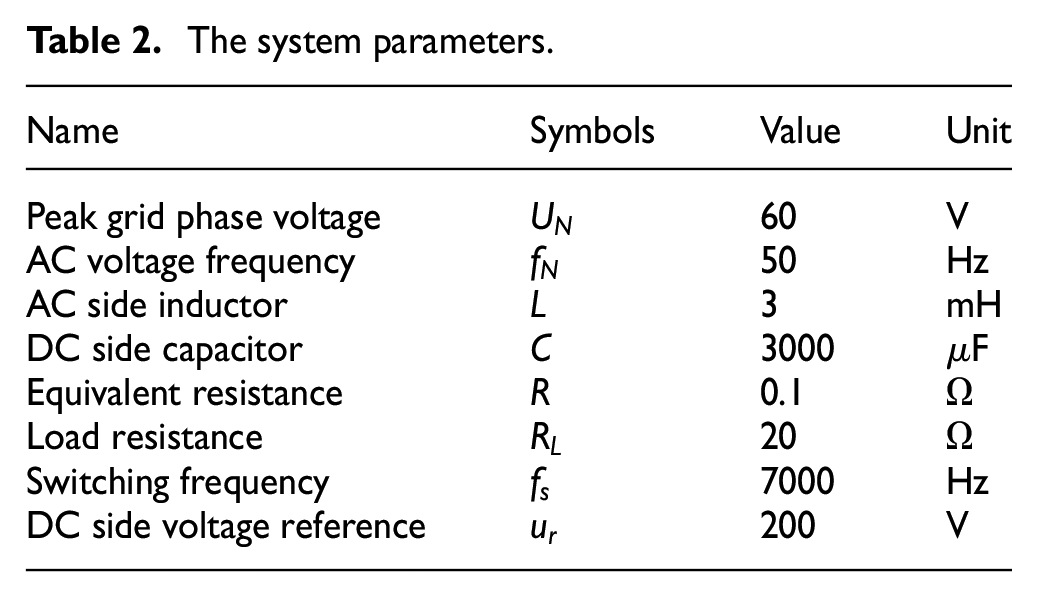
Through the relevant information the interval of the commonly used operating parameters of the PWM rectifier is obtained literatures,34,35 and the system parameters for the simulation of this paper are determined as shown in Table 2. Three-phase PWM rectifier simplification modelling created in MATLAB software for experimentation.
The system parameters.
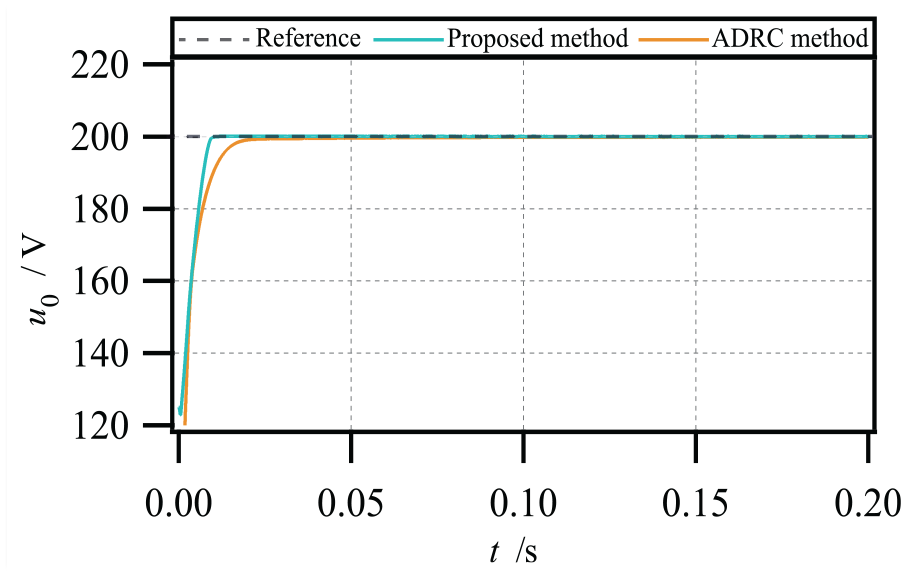
Steady-state operation simulation
As can be seen from the curves in the result plots of Figure 8, the strategy that we propose in this paper possesses following advantages of shorter response time and smoother voltage profile compared with the conventional ADRC method.
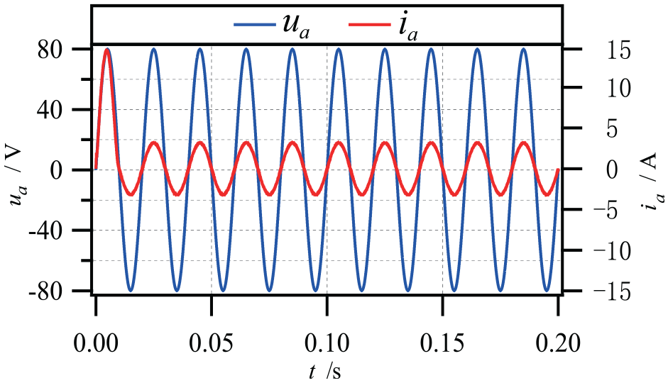
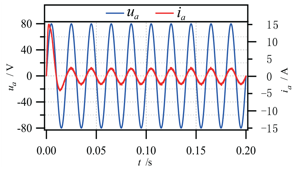
Figures 9 and 10 respectively illustrate rectifier phase A voltages and currents waveforms under the two control methods. From the waveforms, it is observed with proposed control method that the sinusoidalisation of the same phase voltage and current is achieved after 0.1 s, while the traditional ADRC control method can also sinusize the current at 0.1 s, but within 0.1 s at the beginning, the current can be sinusoidal. The phase is inconsistent with the voltage, the current in the subsequent results will spike at the peak, and the buffeting is more obvious. However, the phase of our method is basically consistent with the voltage within 0.1 s, and the current curve is smooth without obvious spikes.
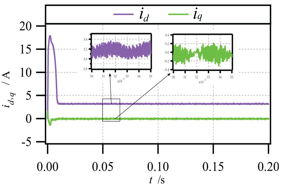
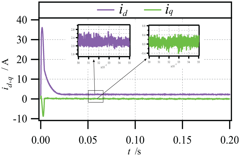
Figures 11 and 12 reflect the
Figures 13 and 14 reflect total harmonics distortion (THD) value and harmonic frequency of the system. The THD value directly reflects system’s harmonic content. Lower values are better for the power quality in a system. Observations and conclusions from the figure, harmonics of a system are generally concentrated on odd harmonics, and the THD value of the proposed control method is 0.44%, which is 1.85% points lower than that of the traditional method of 2.29%, indicating that the proposed method has a good control effect under steady state operation.
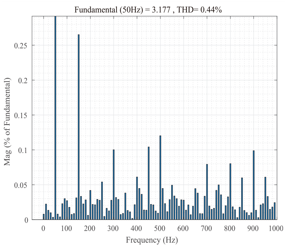
THD value with this paper.
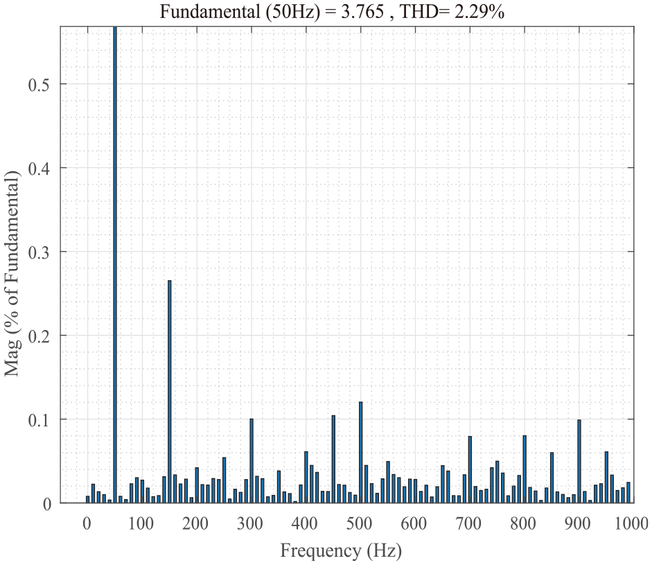
THD value with ADRC.
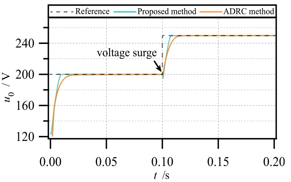
Voltage surge simulation
Through the previous tests, we verified both availability and excellence in the method in steady-state situations. Next, we carried out theoretical experiments by simulating the sudden voltage change caused by the external environment. The steady state voltage of 200 V was set to change to 250 V at 0.1 s, and the results of the experiment are analysed as follows.
The simulations in Figure 15 lead to these conclusions: the voltage starts to change at 0 s and reaches the given value, when the voltage changes abruptly, the DC voltage can be stabilized near the new DC voltage reference value after a short time under the two control strategies. The voltage will not be distorted because of the sudden change of the AC voltage, both of them can achieve a good following, and the dynamic response speed is faster. The response time difference between the proposed method and the ADRC method is not much, and both delays are smaller, but proposed method has much shorter regulation period. A control method proposed in this paper has some advantages over the ADRC control method.
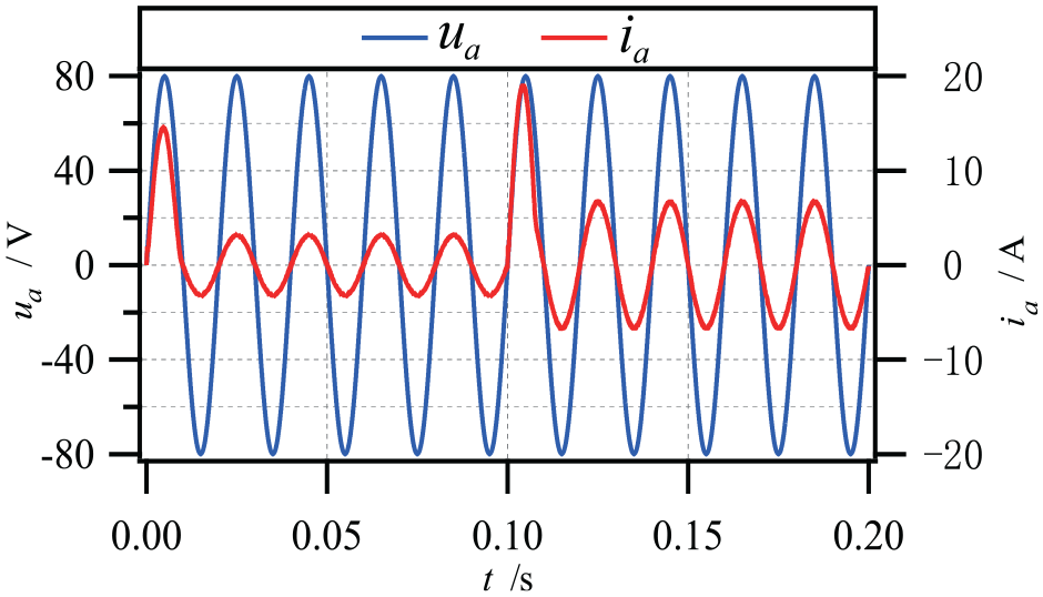
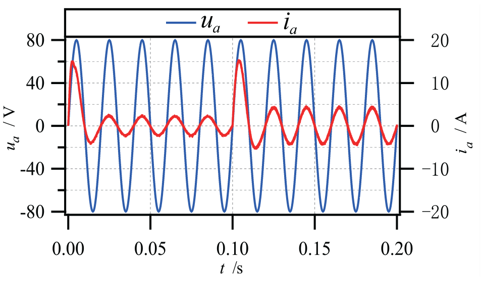
Figures 16 and 17 respectively illustrate rectifier phase A voltages and currents waveforms with the two control methods loaded into the controller. From the waveforms, We could find the two control methods could sinusoidalise in-phase voltages and currents within 0.01 s when a sudden voltage surge occurs. The phase of this paper’s method is basically consistent with the phase of the reference voltage at 0.01 s, and the current curve is smooth without obvious spikes, it is capable to achieve fast following of voltage and current.
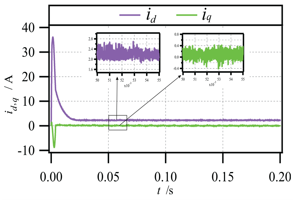
Waveforms for the active and reactive currents in a system under the rotation axes d and q are reflected in Figures 18 and 19. From the figures, it can be observed the proposed method is effective in suppressing the current jitter generated. When a sudden voltage change occurs in 0.1 s, the current using the proposed method in this paper can quickly reach stabilisation in 0.02 s, and the reactive current fluctuation is small.
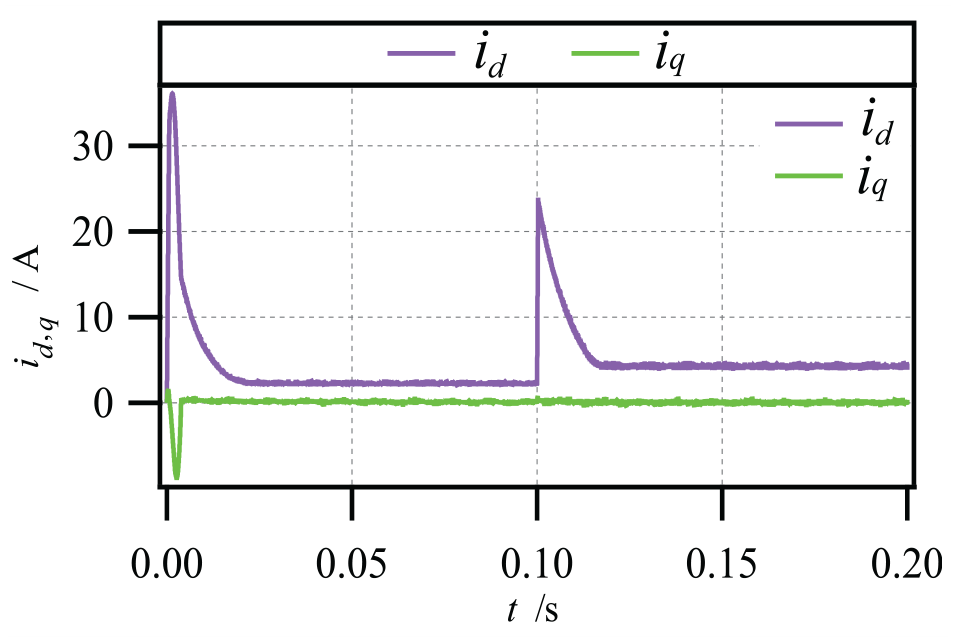
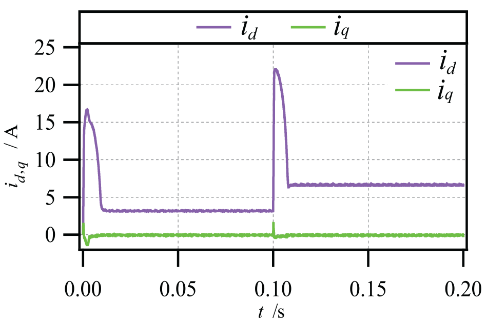
From the figures, it is observed that the proposed methods have good dynamic and stability effectiveness even under sudden voltage surge, and has obvious advantages compared with the traditional method in voltage stability time and current sinusoidal waveform.
Load transformation simulation
Next, we conducted theoretical experiments by simulating the load transformation. The steady state voltage of 200 V was set to change to 250 V at 0.1 s, and the results of the experiment are analysed as follows.
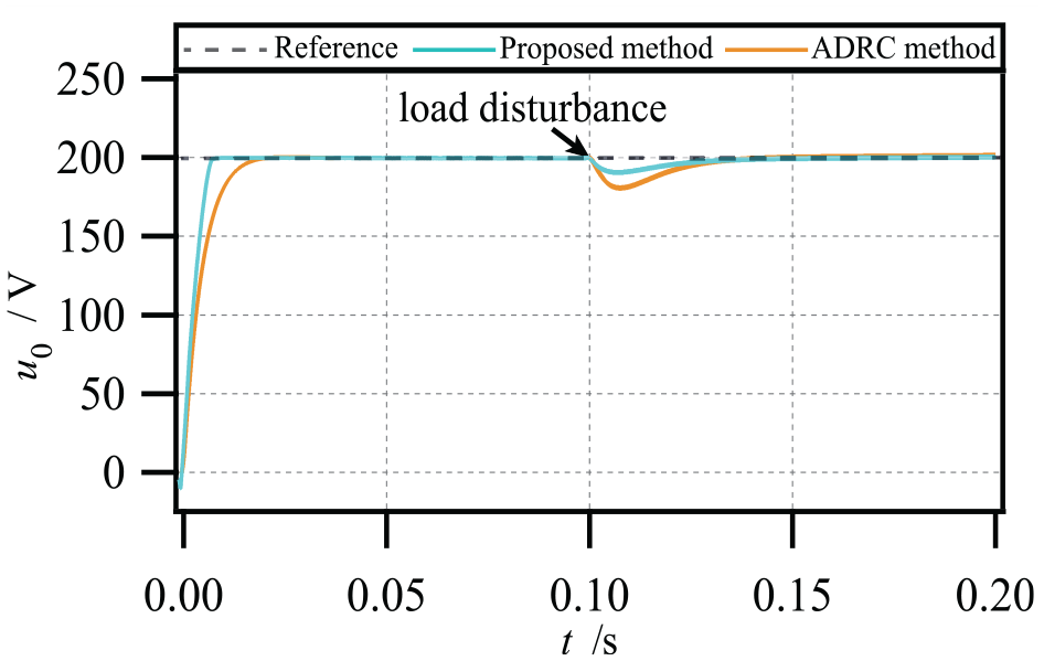
From the simulated outcomes in Figure 20, we can conclude that compared to conventional ADRC control method, which proposed control methods have some advantages in response time, the voltage profile fluctuates is less when it is affected by the load transformation, it recovers quickly and continues to follow the reference voltage, and the voltage profile is also smoother. However, the conventional ADRC control method is significantly weaker than our proposed method in terms of response time.
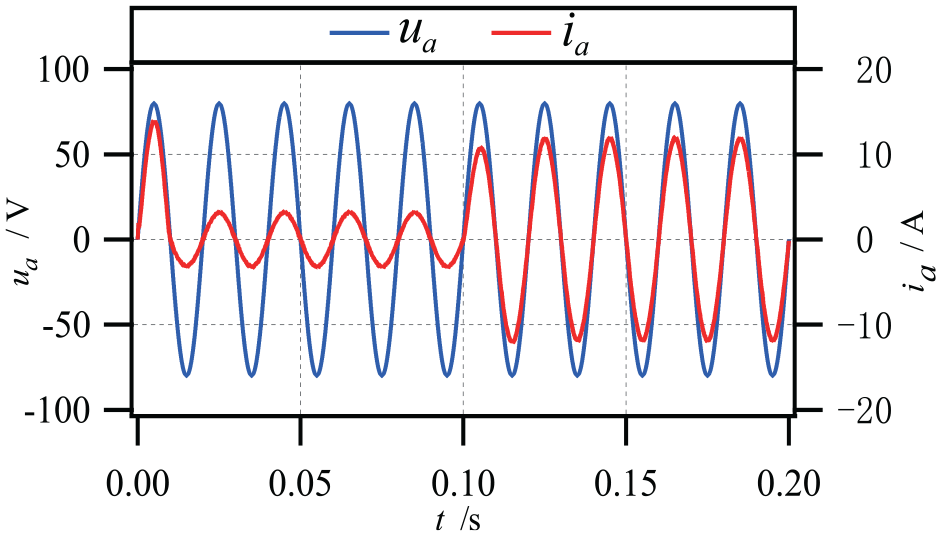
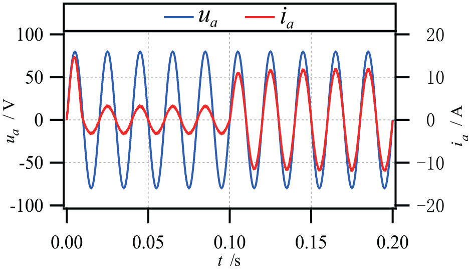
The waveforms for voltage and current in phase A in the rectifier under load transformation with the two control methods as shown in Figures 21 and 22. From the waveforms, it is observed that a control method of the paper achieves in-phase voltage and current and achieves sinusoidal current after 0.01 s, while the conventional ADRC control method also achieves sinusoidal current at 0.01 s, but the current can be sinusoidal in the beginning of the 0.01 s. The phase is not consistent with the voltage, the current in the subsequent results will be spiked at the peak, and the buffering phenomenon is more obvious. In contrast, our method is basically consistent with the phase and voltage within 0.1 s, the current curve is smooth without obvious spikes, and when a load transformation occurs in 0.1 s, our proposed method can respond quickly and the following curve is smoother.
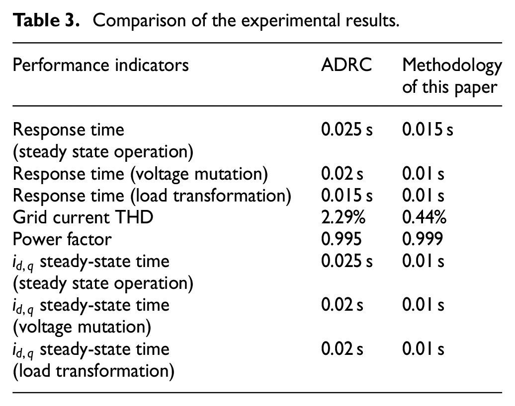
The data from the experimental results were collated and compared, as detailed in Table 3.
Comparison of the experimental results.
Conclusion
This paper uses an underactuated characteristic of PWM rectifiers system to verify the feasibility of its double closed-loop control structure, and conducts controller theory analysis and design, and system performance analysis. The terminal fuzzy sliding mode control based on EID error estimation is designed to achieve current stabilization in a shorter period of time, which can effectively solve the problem that the unknown system sliding mode gain design is too large, reduce the system current jitter and vibration, and improve the system power efficiency. For the ADRC control method in the face of the problem of the DC voltage square wave pulses are too large, the input disturbance elimination feature of EID error estimation is utilized to reduce the voltage square wave fluctuation interval and enhance the system working performance. Experimental tests demonstrate the proposed algorithm achieves the fast DC voltage response and unit grids powers operating for PWM rectifier. It improves the response rate of DC side voltage in steady state operation, has a low THD value, reduce the harmonic content of the control system, commend to better stability, dynamic properties indexes and improves energy qualities under sudden voltage surges and load transformations, as well as improving system perturbations resistance.
Footnotes
Declaration of conflicting interests
The author(s) declared no potential conflicts of interest with respect to the research, authorship, and/or publication of this article.
Funding
The author(s) disclosed receipt of the following financial support for the research, authorship, and/or publication of this article: This research was funded by the Nature Science Foundation of Hubei Province (No. 2023AFB380), the Graduate Innovative Fund of Wuhan Institute of Technology (No. CX2023550, No. CX2023578), the Hubei Key Laboratory of Digital Textile Equipment (Wuhan Textile University) (No. KDTL2022003), the Hubei Key Laboratory of Intelligent Robot (Wuhan Institute of Technology) (No. HBIRL202301), and the Open Research Fund of Vehicle Measurement Control and Safety Key Laboratory of Sichuan Province of Xihua University (No. QCCK2024-0011).
Data availability statement
Data sharing not applicable to this article as no datasets were generated or analysed during the current study.