
Abstract
The common dual-pulse-width-modulation converter adopts the independent method to control the rectifier and inverter, which has the defects including direct current voltage fluctuation, slow system response and so on. A coordinate strategy of dual-pulse-width modulation based on direct power control with load power feed-forward is proposed in this paper. The fixed switching frequency method with space vector pulse width modulation is provided to overcome the instability of power devices, caused by the hysteresis comparators in the conventional direct power control. With the analysis on the dynamic performance of load power feed-forward coordination, the principle of load power feed-forward is introduced to control the dual-pulse-width-modulation converter. According to the state variable of the alternating current motor, the load power is estimated to construct the feed-forward channel. The experimental results show that the proposed coordinate control method has rapid response, direct current bus voltage fluctuation minimization, lower capacity and unit power factor.
Keywords
Introduction
Recently, the dual-pulse-width-modulation (PWM) converters occupy the unit power factor of grid side, direct current (DC) bus voltage constant controllability and energy bidirectional flow and so on. These advantages make them obtain the more extensive applications, such as industry transmission, wind power and other occasions.1–6 In the conventional dual-PWM converter system, the rectifier and inverter are controlled separately, namely controlled independently. These two devices are not related to each other. Therefore, when the load is changed, the system can be adjusted according with this change to affect the whole system performance. Especially in the case of high requirement of speed regulation system, the alternating current (AC) motor’s states may change frequently, the rectifier and inverter with independent control are slightly inadequate to system performance.
How to suppress the DC bus voltage fluctuation effectively is one of the keys to control the dual-PWM converter, which is focused on by more scholars. The double closed-loop construction of voltage and current is adapted to the load current forward-feed control, which can change the current reference value of the inner loop of motor. The low pass filter is used to get the average value, and the dynamic response speed of the system is reduced.7–12 The current balance control method can maintain the input current equal to the output current in the converter, so that the current of capacity is close to zero, the dynamic response is fast and DC voltage fluctuation is small, but it is difficult to achieve.3,13,14
The direct power control strategy is proposed with the instantaneous reactive power theory applied to dual-PWM converter.15–17 The fast dynamic response of the AC motor is realized by the real-time control of the instantaneous active power and instantaneous reactive power. The system is designed simplicity without the traditional current inner loop, the coordinate transformation and PWM modulation module. Moreover, the double table control strategy of alternating with active power and reactive power is put forward to improve the system dynamic and static performance and reduce the DC dynamic voltage drop.18,19 However, these control strategies independently control the PWM rectifiers. Although the dynamic response speed of the grid side is improved, the whole system is not coordinated. In these methods, the power flow between rectifier side and inverter side is controlled as the same value to reduce the energy difference with rectifier and inverter per unit time, so that the DC voltage has the fluctuation in a small range and DC capacitor value is reduced in the dual-PWM converter.20–22
The active power and reactive power in PWM rectifier is thought as the purpose of the conventional direct power control, in which bang-bang control is applied. Although the system has rapid response and simple algorithms, it is fatal for load power feed-forward to be unfixed in switching frequency. The requirement on higher sampling frequency makes the system design be difficult. Therefore, a novel direct power control with fixed switching frequency is provided first, and then with the analysis of load power feed-forward coordination control principle in dual-PWM converter, load power value is calculated and its sudden change information is feed-forward to rectifier side, so that the coordination control between rectifier and inverter is accomplished.
The rest of this article is organized as follows. Section “Direct power control system principle” describes direct power control based on switching table and direct power control based on fixed switching frequency, respectively, in the conventional direct power control system. In section “Dual-PWM coordinate control with load power feed-forward,” based on load power feed-forward principle, the dynamic performance of coordination method with load power feed-forward is analyzed, and the coordinate control on Dual-PWM with load power feed-forward is proposed with the properly load power estimation. Section “Experiment and result analysis” discusses the experimental results of the proposed coordinate control method and its comparisons. Section “Conclusion” concludes the study.
Direct power control system principle
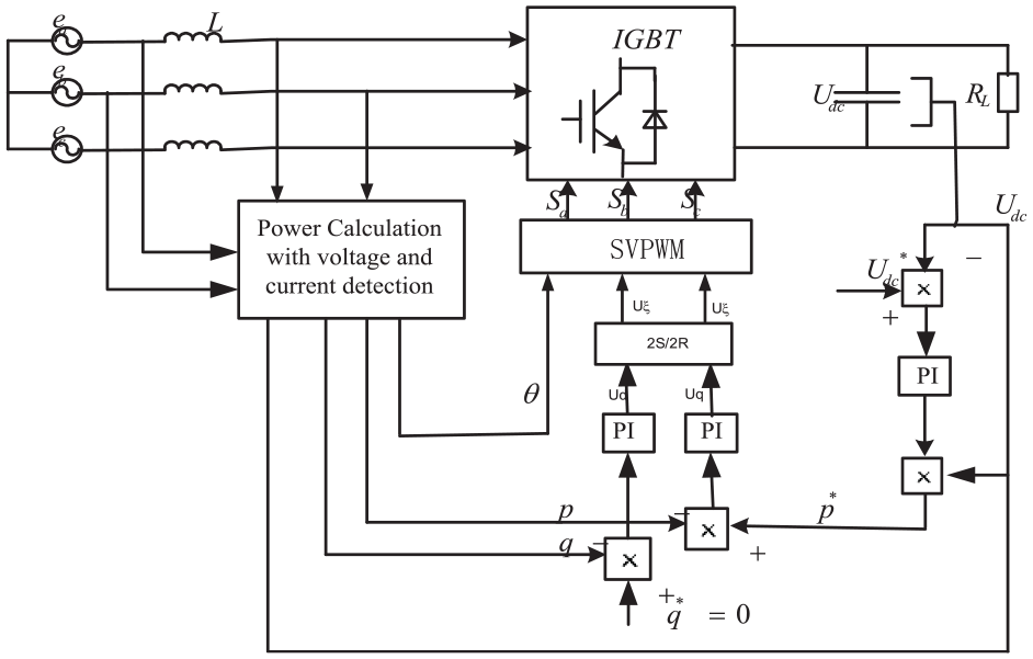
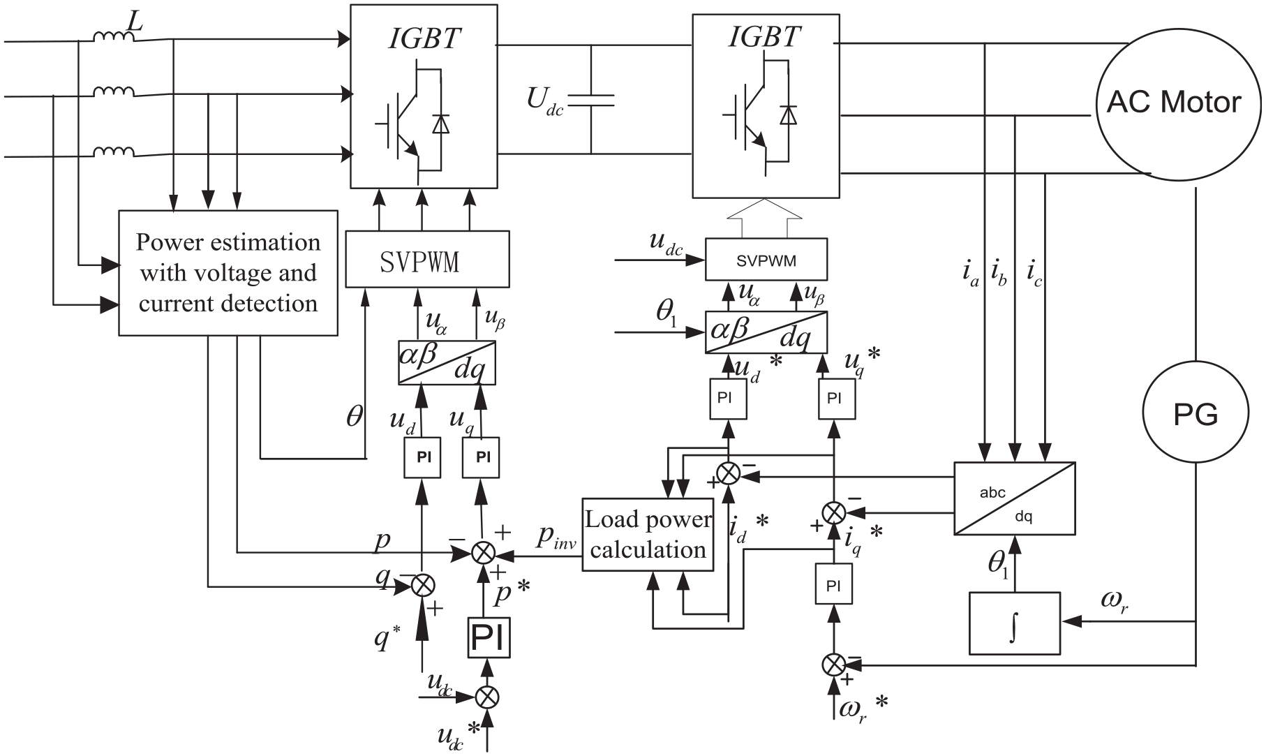
The conventional direct power control is shown in Figure 1. The double closed-loop structure with voltage control outer loop and power control inner loop is adopted. According with theory of instantaneous power, instantaneous active power p and instantaneous reactive power q can be calculated by grid voltage and current. The subtraction value between the set value of instantaneous active power instruction p* and p is put into hysteresis comparator, and the subtraction value between the set value of instantaneous reactive power instruction q* and q is put into hysteresis comparator. Grid voltage signals are used for sector judgment. Hysteresis comparator outputs the switching control signals, in which active power’s reference value is the output value from DC voltage outer loop and reactive power’s reference value is set to zero in order to make the unit power factor of PWM rectifier grid side.
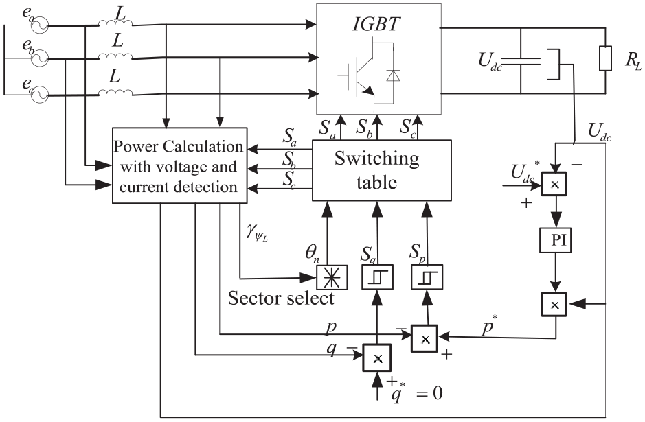
Conventional direct power control system.
Direct power control base on switching table
In the conventional direct power control system, the space vector of voltage must be judged its position. The grid three-phase voltages are converted to two-phase static coordinates voltages according to Clark Conversion, and the space vector of voltage is divided equally into 12 sections on a circle plane. The sector position is judged as equation (1)
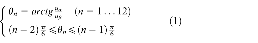
The switching table plays the important role in the direct power control system. The switching table directly affects the performance of system control. Switching vector table, shown in Table 1, is a group of preset vector sequences. According to output of hysteresis compactor and section of grid voltage vector, only one corresponding switching vector is found in the switching vector table. This vector is used to decide the switching signal of three-phase bridge insulated gate bipolar transistor (IGBT).
Switching table of DPC system.
DPC: direct power control.
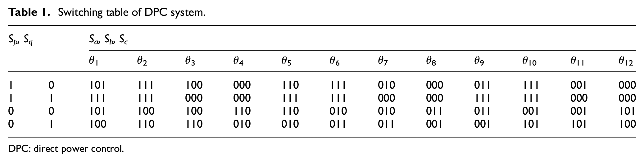
Voltage switching vectors working diagram is shown in Figure 2, in which Us is grid voltage vector; i is actual current vector; and ir is reference current vector; V1 (100), V2 (110), V3 (010), V4 (011), V5 (001) and V6 (101) are six basic voltage space vectors; V0 (000) and V7 (111) are the zero voltage vectors. From Figure 2, it is seen that the phase of actual current is not the same as grid side voltage. In order to achieve unit power factor, the actual current vector should be approached to reference current’s place. i is chosen to be approach to ir as the direction of Us–V6. Similarly, the other positions of i are used the same method to obtain the switching functions of the three-phase bridge IGBT.
Switching vectors diagram.
Direct power control base on fixed switching frequency
Because the conventional direct power control adopts hysteresis comparator and switch voltage vector list as modulation method, there are several sampling periods in each section. In period of time, if the output value of hysteresis comparator is same, the output value of voltage vector is same, either. On the contrary, if the output value of hysteresis comparator is different, the output value of voltage vector in this sampling period is different, either. Switch frequency is high in the sampling period that the output value of voltage vector is different, while switch frequency is low in the sampling period that the output value of voltage vector is same. This situation leads to the unstable switch frequency and much switch loss. According to equation (2), active power and reactive power are the mutual coupling in power mathematical model of PWM rectifier. The hysteresis comparator’s control method can’t uncouple the active power and reactive power. In order to overcome this shortcoming, space vector PWM (SVPWM) is introduced in direct power control system to realize the fixed switching frequency, shown in Figure 3. Difference with the conventional direction power control system, the substation values between instantaneous active power and reference value, as well as between instantaneous reactive power and reference value, are not put into hysteresis comparator, but put into proportional–integral (PI) regulator. The components in two-phase rotate coordinate system are obtained, and the switch function is provided with PWM modulation module. The fixed switching frequency in direct power control strategy realizes the fixed frequency action, as well as the active power and reactive power uncoupled. It is convenience for latter power feed-forward to acquire voltage vectors of any direction. Moreover, the control system has lower total harmonic distortion (THD) value and stronger anti-interference ability.
The diagram of direct power control based on SVPWM.
According to any voltage vector U and its components at α–β coordination, Uα and Uβ are defined as follows
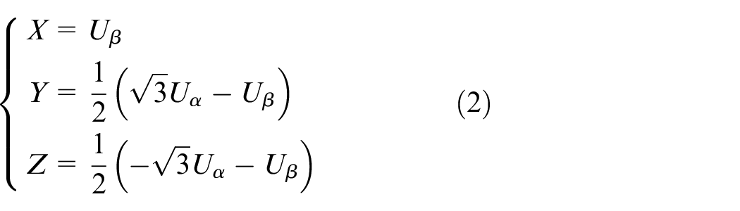
Let N = A + 2B + 4C, N is reference voltage sector. In equation (2), if X > 0, then A = 1, else A = 0; if Y > 0, then B = 1, else B = 0; if Z > 0, then C = 1, else C = 0. The working time of space vector in each section can be directly calculated with reference voltage vectors V. For example, reference voltage U, as shown in Figure 2, is compounded by two neighboring effective space vectors V1 and V2 and zero vector, then

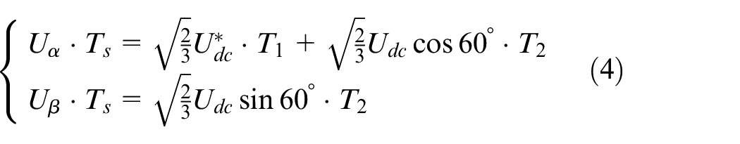
where
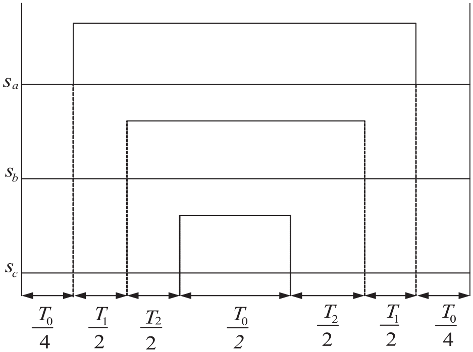
Action time chart of space vector within the fist sector.
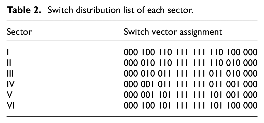
Voltage space vectors are calculated by the method of seven space vectors synthesis to ensure each change involving one switch in any conditions. Each sector’s switch vector assignment table is shown as Table 2.
Switch distribution list of each sector.
Dual-PWM coordinate control with load power feed-forward
Load power feed-forward principle
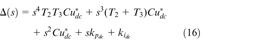
In dual-PWM frequency conversion system, if the rectification part and inversion part’s switch losses are ignored, the power of the DC part capacitance is equal to integration of rectifier and inverter, which is shown as follows
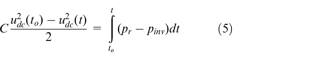

where pr and pinv are the input power and load power of rectifier, respectively; Δudc is the DC voltage’s variation, which is assumed as follows

Equation (7) is taken into equations (5) and (6), and the high-order values are ignored, then
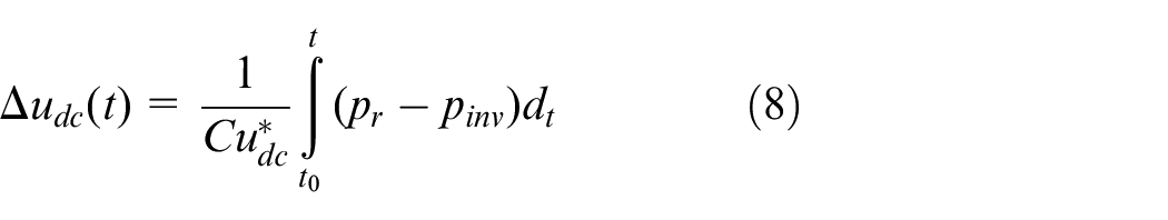
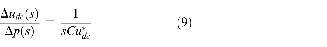
Equation (8) is changed into the frequency domain
In dual-PWM system, the reactive power is consumed at grid side and cannot get through rectifier. The input active power instruction value of rectifier can be represented as follows

where
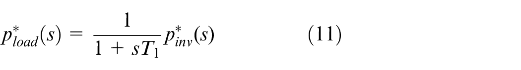
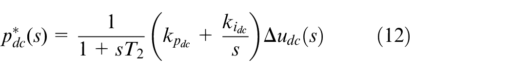
where T1 and T2 are time constants. Equations (11) and (12) are taken into equation (10), then
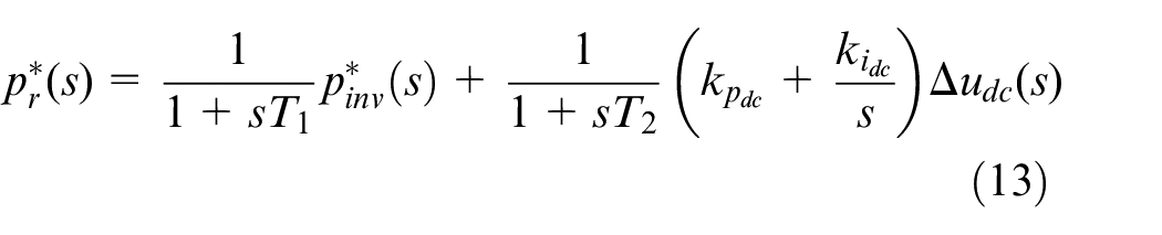
The relationship between instruction value and actual value is equal to a first-order process, then
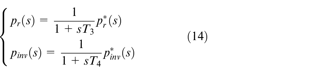
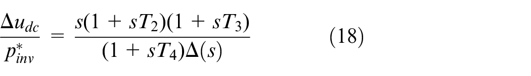
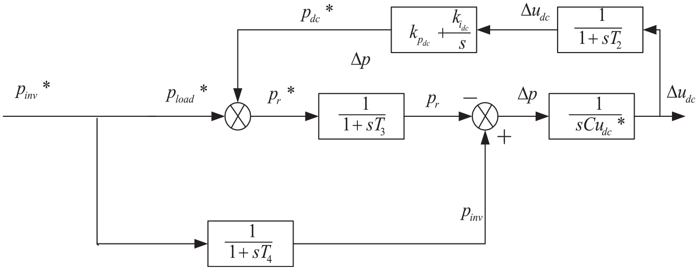
where T3 and T4 are time constants. According to equations (13) and (14), the structure diagram of dual-PWM converter system with power feed-forward compensation control is shown as Figure 5.
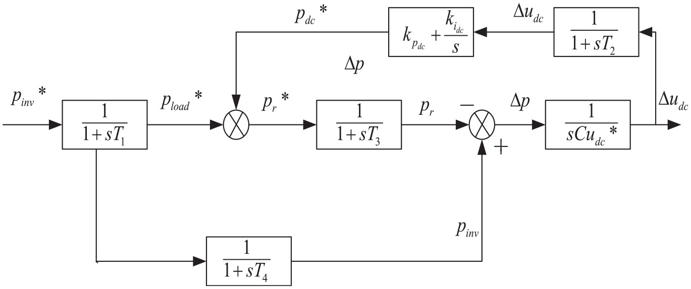
The structure diagram of dual-PWM converter system with power feed-forward compensation control.
Dynamic analysis of coordination with load power feed-forward
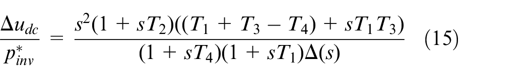
The main reason of DC voltage fluctuation is the energy unbalance caused by the power change of load side. The transfer function between DC-link voltage change and load power instruction is deduced by Figure 5
Usually, because of system sampling and calculation time delay, the time constant T1 from
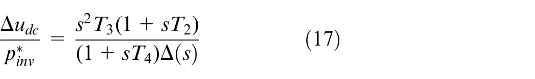
Equation (17) is the function from load power instruction to DC-link voltage fluctuation. The transfer function from load power instruction to DC-side voltage fluctuation with non-load feed-forward coordination control is obtained by the similar method
It is indicated in equation (17), when the measure method is adopted to get load power feed-forward, T1 is larger than T4, which means that the delay time from load power instruction value to feed-forward instruction is longer than output’s respond time. If
The structure diagram of dual-PWM system feed-forward coordination control based on load power estimation.
The system closed-loop transfer function with load power estimation is deduced as follows
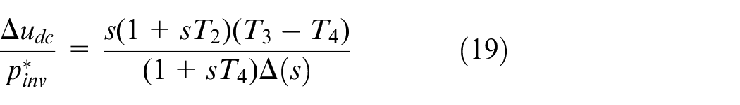
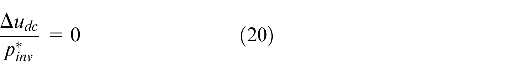
It is indicated in equation (18), with the method of load power estimate, if T3 is controlled to equal to T4, which means that the time constant between input power value and load power respond value is equal. DC-side voltage’s fluctuation is influenced by change of load power no longer, then
However, in practical application, estimation is not absolute exactly. There are all kinds of errors, which absolutely influence DC voltage fluctuation. The definition is as follows:
The transfer function between DC voltage fluctuation and estimate error is obtained by Figure 6
It is simplified
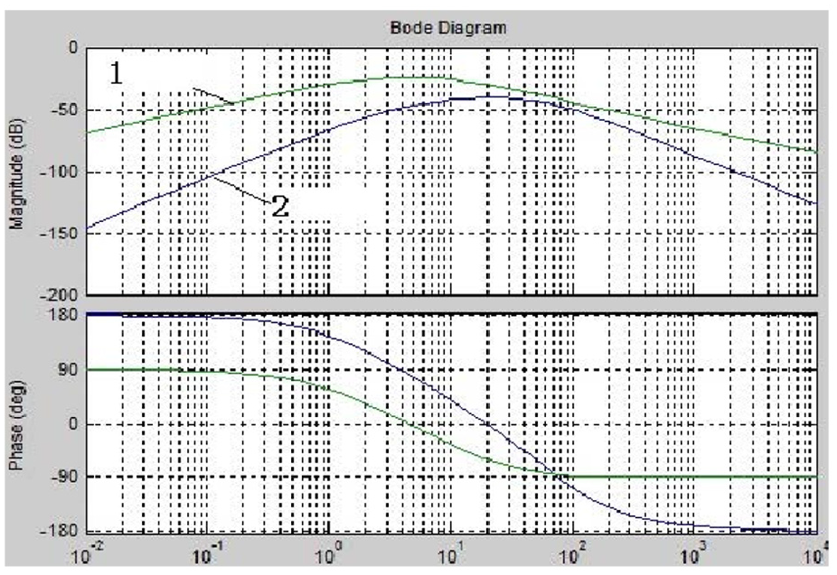
In Figure 7, Curve 1 is Bode diagram without introduction of power feed-forward, and Curve 2 is Bode diagram with introduction load power feed-forward. When coordinate control with load power feed-forward is applied in the dual-PWM frequency conversion system, this system has a stronger restrain function to DC voltage’s fluctuation (See Table 3 for controller parameters).
Bode diagrams under two different control modes.
The controller parameters.
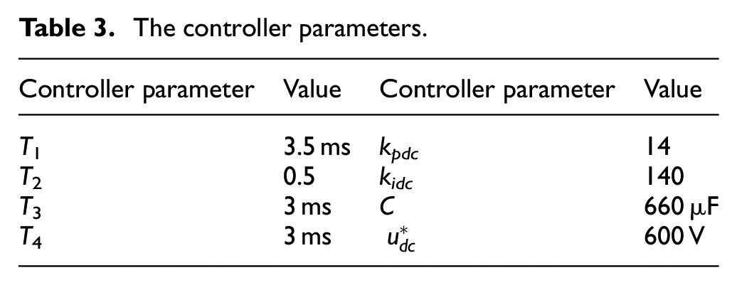
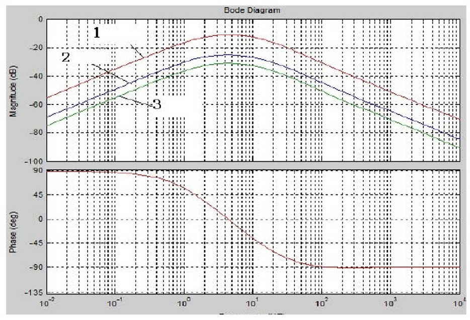
Figure 8 is Bode diagram of equation (22), Curves 1, 2 and 3 are estimation error Bode diagrams, in which estimation error values are double times, same and one-tenth times of error value, respectively. From these curves, it is obvious that estimation errors have a stronger influence on system fluctuation DC voltage when the load power feed-forward coordinate control is adapted. The less the error value is, the better the performance of system has.
Bode diagrams under different errors.
Load power estimated
If the power loss of inverter bridge circuit is negligible, load power is usually the power of AC motor consumption. Supposed that the load power is Pinv, there are several calculation methods for load power as follows:
1. Measurement calculation
The load power is equal to the power that enters into the inverter bridge circuit. If the current that enters into the inverter bridge is measured, the load power is obtained by this current and DC-link voltage

This method is simple, but the current that enters into the inverter part is usually the pulse. In addition, in practical application, DC part is consist of multilayer plate structure. It fixes with IGBT module in order to reduce stray inductance. In this case, it is difficult to fix current sensor. Even if the current sensor is installed, the load current iL outputs out-of-shape plus wave because inverter circuit switch is continuously changes. It is hard to find a suitable instantaneous value to replace cycle average value in a PWM cycle. Although the high-frequency impulse influenced by adding high-pass filter is removed, the filter lowers the system response speed. This method is hard to use.
2. Calculation with duty radio
The dead zone effect, the turn-on and turn-off time of power devices are all not negligible, the input power of inverter part can be calculate as

In this method, the measured DC bus voltage, inverter bridge control signals duty ratio and the three-phase currents of motor are combined to approximately estimate.
3. Estimation with motor state variables
The state variables of motor’s vector control in inverter part are combined with instantaneous power theory to estimate the load power, shown as the following

This method is essentially the same as the second method. Those two methods have not the extra sensors and reduce the cost of system. However, when this method adopts power feed-forward, there is a big delay time between actual power and load power, which influences dynamic performance of system.
Coordination with load power feed-forward based on direct power control
In coordination control system of dual-PWM with load power feed-forward, the grid side rectifier adopts direct power control strategy with fixed switch frequency, the inverter part adopts vector control strategy depending on directional rotor linkage. From vector control, the motor stator current component in two-phase rotation coordinate is used to obtain the instantaneous power. The power instruction in the inverter part is feed-forward to active power output instruction of grid side. On this way, rectifier in grid side can output base on the need of load power to keep the balance of two sides’ power, so the voltage of DC-link is stable. Ignoring the switch loss of power devices in inverter part, the output power of AC motor is equal to load power. Power instruction of motor’s output value can be obtained by the vector control. In this method, the outer loop has litter pressure to regulate the grid rectifier voltage and system has the rapid dynamic response
Experiment and result analysis
Simulations and analysis
In order to verify the correctness of the dual-PWM converter based on load power feed-forward control which is discussed in this paper, MATLAB/Simulink is applied to simulate. Simulation model is shown as Figure 9. Simulation parameters are set as follows: three-phase power’s voltage effective value is 220 V, DC capacitance C is 200 µF, DC voltage
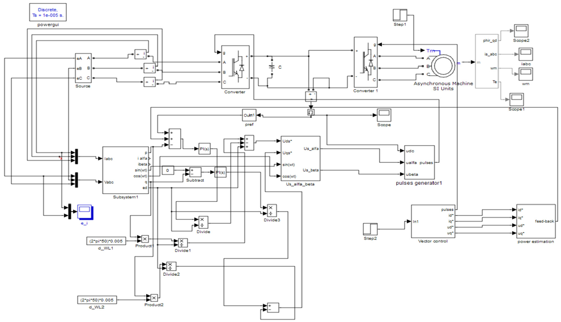
The simulation model of dual-PWM converter based on load power feed-forward control.
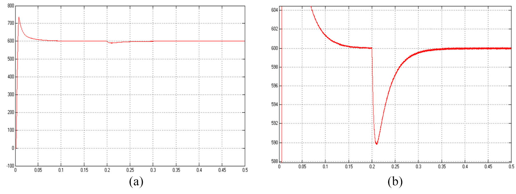
Figure 10(a) and (b) shows the waveforms of DC-link voltage and its amplification in dual-PWM conversion system without load current feed-forward. Figure 11(a) and (b) shows the waveforms of DC-link voltage and its amplification in dual-PWM conversion system with load current feed-forward. It is obvious that DC-link voltage fluctuation with load current feed-forward coordinate control is smaller than the fluctuation without load current feed-forward when motor’s torque suddenly changes from 10 to 15 kg m2 at 0.2 s. The fluctuation with load current feed-forward coordinate control is about 10 V, and system can quickly recover to voltage instruction value after the load suddenly changes. As a whole, the results show that load current feed-forward coordinate control can restrain DC-link voltage fluctuation well when the load state suddenly changes, and the system has the rapid response.
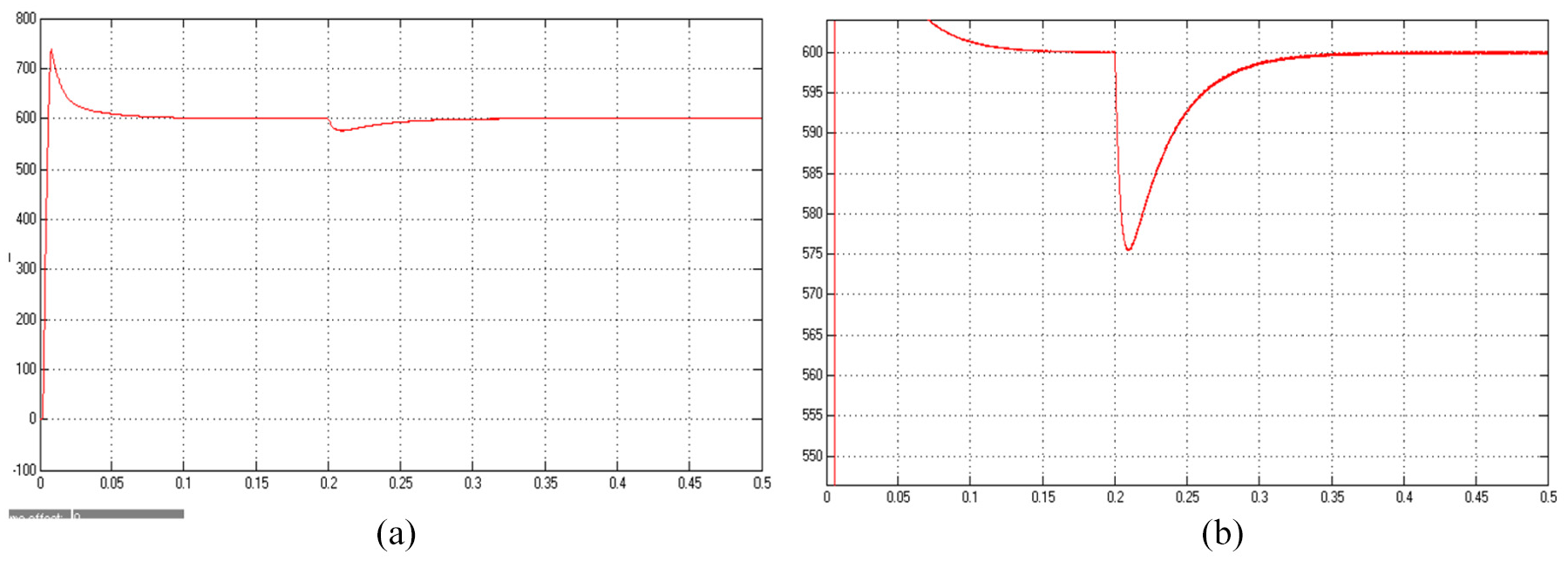
The simulation waveforms of DC-side voltage under independent control method: (a) DC-link voltage and (b) the amplification of DC-link voltage.
The simulation waveforms of DC-side voltage under feed-forward control method: (a) DC-link voltage and (b) the amplification of DC-link voltage.
Experiment and analysis
The experimental structure diagram of dual-PWM load power information feed-forward coordinate control is shown as Figure 12. The experimental parameters are same as simulation.
The experimental structure diagram of dual-PWM load power information feed-forward coordinate control.
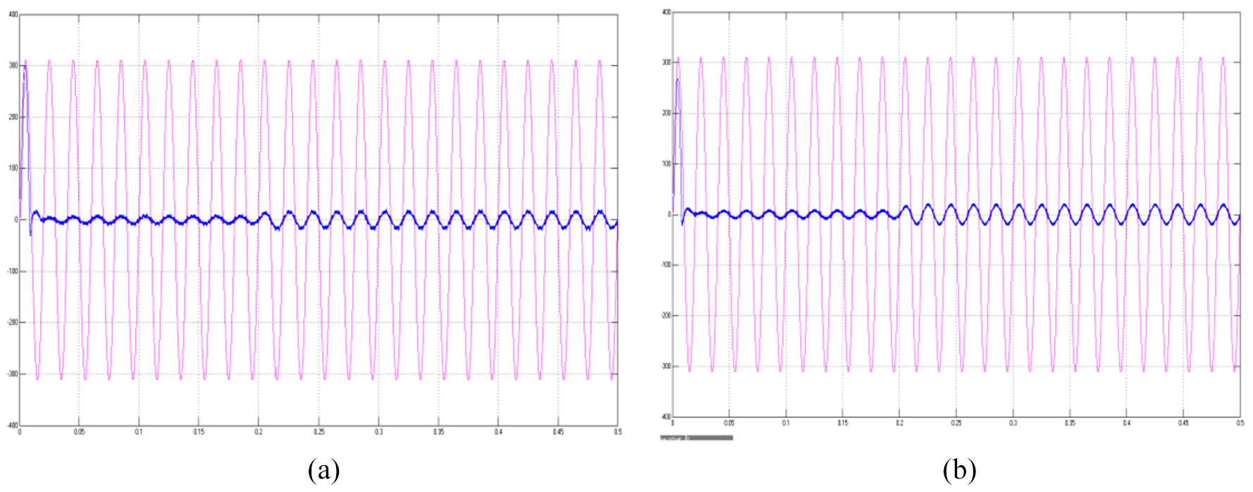
Figure 13(a) and (b) depicts voltage waveforms and current waveforms of the dual-PWM conversion system without load power feed-forward and with load power feed-forward, respectively. It can be seen that voltage and current keep same phase. Particularly, with load current feed-forward, the voltage and current waveforms of grid side are more sinusoidal. The current waveform has less burr and is more smoother, and its harmonic content is lower than that without the feed-forward.
The grid side waveforms of voltage and current: (a) without load power feed-forward and (b) with load power feed-forward.
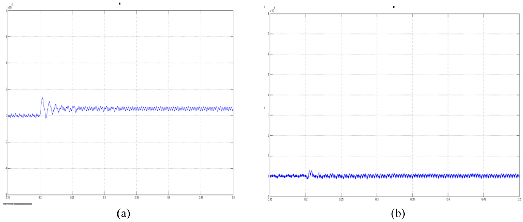
Figure 14 shows the waveforms of active (a) and reactive (b) power without feed-forward control. It is obvious that the active power can reach a given value after a period time and the reactive power fluctuates if motor’s torque changes suddenly at 0.2 s.
The waveforms of active and reactive power without feed-forward control: (a) active power and (b) reactive power.
Figure 15(a) and (b) depicts the waveforms of active and reactive power waveform in grid side with power feed-forward control. It can be seen that active power can quickly reach to the set value and keep stable when motor’s torque changes suddenly at 0.2 s, reactive power can keep almost zero and its fluctuation is little. Comparing Figures 14 and 15, the results show that the dual-PWM converter coordinate control with load power feed-forward can reduce DC capacitance and restrain DC voltage fluctuation, rectifier is able to output the power with load need to achieve energy saving and rapid power respond.
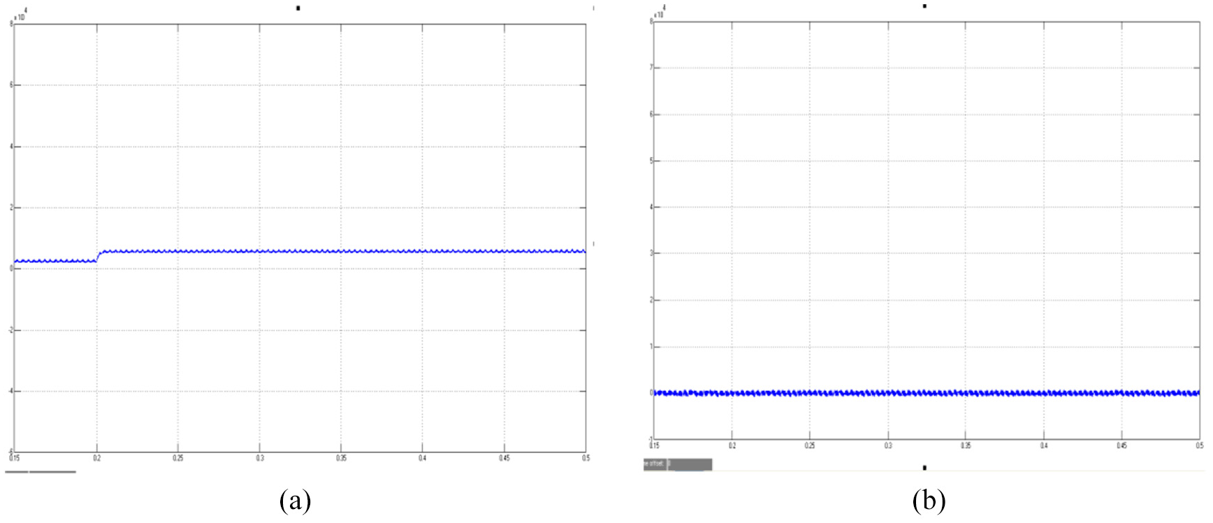
The waveforms of active and reactive power under load power feed-forward control: (a) active power and (b) reactive power.
Conclusion
In this paper, the coordinate control method to dual-PWM converter with load power feed-forward is mainly discussed. PWM rectifier’s conventional direct power control is introduced. With the analysis of conventional direct power control’s shortage, direct power control of fixed switching frequency for grid side rectifier and the theory of power feed-forward are adopted. Vector control is applied to the inverter-side motor, in which estimate method of concentrated load power is used. This method can estimate load power based on motor’s state variable, which is used to set up feed-forward channel of load power. Simulation results show that the proposed coordinate control method has rapid response, DC bus voltage fluctuation minimization, lower capacity and unit power factor.
Footnotes
Declaration of conflicting interests
The author(s) declared no potential conflicts of interest with respect to the research, authorship and/or publication of this article.
Funding
The author(s) disclosed receipt of the following financial support for the research, authorship and/or publication of this article: This work is supported by National Science Foundation of China (U1704157), National Key Research and Development Program of China (2017YFB0306400), Scientific and Technological Innovation Leaders in Central Plains (194200510012), Science and Technology Innovative Teams in University of Henan Province (18IRTSTHN011) and CSC Scholarship.