
Abstract
Numerical simulation has been conducted on a transonic contra-rotating axial compressor to investigate the shock wave and flow characteristics under various operation conditions. Results indicate that the shock-wave structure in the downstream rotor (Rotor 2) of transonic contra-rotating axial compressor is more complex than that in the upstream rotor (Rotor 1). Under the choke condition, a double shock-wave structure appears in the Rotor 2 leading to serious loss. Moving to the design condition, a single shock wave appears at the root and middle sections of blade of Rotor 2, while a normal and an oblique shock wave arise at the blade tip. Under the near-stall condition, the shock structure has no obvious difference from other conditions at the blade root of Rotor 2 but it becomes further off-body at the middle blade. During the switch of transonic contra-rotating axial compressor from the choke to the near-stall condition, the separation bubble on the pressure surface of Rotor 2 decreased gradually due to the increasing aerodynamics load. The suction surface experiences the weakest separation at the design point. Alternatively, the tip leakage flow becomes stronger with maximum loss at the near-stall condition. The radial matching of the meridional passage of Rotor 2 with the routing flow parameters is the potential optimization aspect.
Keywords
Introduction
As an unconventional aerodynamic configuration, contra-rotating axial-flow compressor/fans (CRAC) could be a promising technology to enhance the work capacity of per stage unit. Compared with conventional compressor, the dimensions are reduced, that is, more compact. The contra-rotating compressor has advantages of improving the thrust–weight ratio of aero-engine in future. Young 1 earlier proposed a contra-rotating fan concept and subsequently the National Aeronautics and Space Administration (NASA) had designed and tested the performance of contra-rotating compressor. 2 The researchers in MIT implemented amount of important works on the design, test, and flow control of the contra-rotating compressor.3–6 Wang et al. 7 carried out an unsteady simulation on the shock-wave structure and the interaction between coupled blade rows in a contra-rotating turbine. Recently, Mistry and Pradeep8,9 experimentally studied the effect of rotating speed, axial spacing, and so on on the performance of a low-speed contra-rotating fan. A boundary layer suction flow control strategy has been experimentally studied by L Shi et al. 10 to actively improve the contra-rotating compressor. Their results showed that the suction can efficiently improve the pressure ratio and efficiency. It has to be mentioned that these documented studies are limited to the low-speed regime, that is, subsonic compressor. Regarding the conventional transonic compressor, Puterbaugh and Brendel 11 investigated interaction between the tip leakage flow and the shock wave in a transonic compressor rotor and revealed that the interaction is fundamentally the result of the change in momentum brought about by the shock-induced pressure rise. Chima 12 proposed the tip clearance model to calculate the effects in transonic compressor and it predicted well the performance results but disagreed with the measured data of casing separation and wake decay. Biollo and Benini 13 redesigned a transonic rotor based on Rotor 37 model to modify the three-dimensional shock structure and improved the shock/boundary layer/tip clearance interaction. Denton 14 computationally studied the effects of blade lean and sweep on the transonic fan performance. It was found that this feature has little effect on the tip shock but there is significant shock sweep on the lower down blade. Passrucker et al. 15 tested a transonic compressor with forward sweep design and found it can divert the flow toward the blade tip region to benefit the flow stabilization. Wadia et al. 16 numerically found that the forward sweep transonic rotor could reduce the clearance sensitivity to tip flow. Gorrell et al. 17 employed particle image velocimetry (PIV) and computational fluid dynamics (CFD) approaches to reveal that strong vortices of the wake can break up the rotor bow shock which causes large loss in transonic compressor. Estevadeordal et al. 18 studied again blade–row interactions in a transonic compressor using PIV and identified the interactions between stator wake and rotor-bow-shock flow. Castaneda et al. 19 numerically analyzed transonic compressor rotors with inlet swirl distortion and suggested that ground vortex core location and vortex rotational direction greatly affect the shift of the speed line. Benini et al. 20 implemented numerical investigation on the efficiency enhancement in transonic compressor rotor using synthetic jet and found that the efficiency increment is up to 1.4%. Kan et al. 21 implemented numerical simulations and topological analysis to study the stalling process of a transonic compressor. The steady three-dimensional vortex structure of stator under transition conditions was established, and the mechanism of the stalling process was revealed from the perspective of the vortex structure evolution. Liu et al. 22 conducted numerical investigation to reveal that the inlet distortion deteriorates the performance of both the upstream and downstream rotors resulting in reduction of total pressure ratio, efficiency, and stall margin of the transonic contra-rotating compressor. To improve the flow in transonic compressor, Hu and Wang 23 proposed a compressor design concept by increasing the axial velocity of the rotor outlet to reduce the degree of reaction for the sake of avoiding the flow separation. Han and Zhong 24 researched the effect of blade tip winglet on the performance of a highly loaded transonic compressor rotor. It is found that the interaction of the tip winglet with the tip flow is different when the winglet is located at suction side or pressure side of the blade tip and therefore the performance. Biollo and Benini 25 reviewed recent advances in transonic axial compressor aerodynamics involving the design, optimization, and active/passive flow control.
Regarding the transonic contra-rotating axial compressor (TCRAC), due to the contra-rotating installation and supersonic flow, the internal flow and shock-wave structures are more complex, particularly for the downstream rotor. Additionally, the complications can be augmented under the near-stall operation, which has a significant impact on the overall performance of TCRAC. Thus, it is essential to comprehensively explore the fundamental physical knowledge of shock and flow in TCRAC. However, few studies on this topic can be found in the literatures. In this study, numerical simulation was carried out on a transonic contra-rotating compressor wherein the shock-wave structure and flow characteristics under different operation conditions are investigated. This work is able to provide theoretical fundamentals for further optimizing the design of high-efficiency TCRAC and additionally guide the engineers to perform active/positive flow control strategies in TCRAC.
Computational model and numerical methodology
TCRAC model
The geometric model of the TCRAC used in this study is shown in Figure 1 where the upstream and downstream rotors are denoted by Rotor 1 and Rotor 2, respectively. The TCRAC layout is axial intake type and without inlet and outlet guide vanes. The studied TCRAC is designed by author’s research group. The main geometric and aerodynamic parameters of the compressor are shown in Table 1.
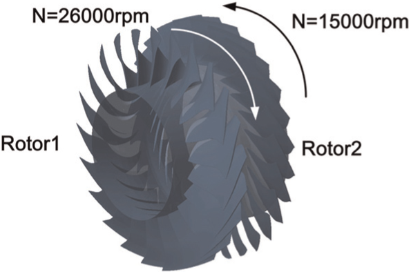
Transonic contra-rotating axial compressor (TCRAC).
Specifications of TCRAC.

TCRAC: transonic contra-rotating axial compressor.
Validation and verification
In this work, the EURANUS solver is employed to solve the compressible Reynolds-averaged Navier–Stokes equations and the S-A turbulence model is used to close the equation system. The single passage flow with periodic boundary condition is simulated. The interface between rotor rows is treated by the frozen rotor method. 26 To validate the present numerical method, the transonic NASA37 rotor is simulated first and compared with the published experimental27,28 and computational results. 29 The inlet boundary condition is set up with total pressure (101,325 Pa), total temperature (288.15 K), and intake direction. At the outlet, the averaged static pressure is set up. The solid surface is set as no-slipping adiabatic wall. The comparison between the computational and the experimental data in terms of pressure ratio and isotropic efficiency is shown in Figure 2 where a good agreement has been revealed. The mass flow rate here all is normalized by the corresponding chocked mass flow rate. The simulation underestimated the efficiency value, similar deviation can also be revealed from studies by Hofmann and Ballmann 29 and Ameri, 30 which might due to the numerical adiabatic boundary condition at solid wall cannot fully represent the reality. Around the operation boundaries, the reason of discrepancy between simulation and measurement is considered to be the strong unsteady flow in the compressor, which needs a transient simulation to get a full understanding. In the present simulation, to keep the periodicity consistent between rotors interface, the scaling method was applied. Therefore, using a series of frozen rotor simulations at different relative displacements and averaging the results are avoided in the present approach.

Performance characteristics of Rotor 37 for validation: (a) total pressure ratio and (b) efficiency.
Performance calculation of TCRAC
Grid independence analysis was carried out first to determine appropriate mesh resolution for the present TCRAC. Three mesh systems with different grid resolutions are simultaneously computed. The grid design is shown in Figure 3. The axial, radial, and the circumferential grids distributions of the rotors, the distribution of the gap grids, and the total grids element number are listed in Table 2. Figure 4 shows the performance curves of the compressor at different design speeds with different grid resolutions. The results are obtained after the solution convergence is totally reached. It can be seen that both the pressure and the efficiency curves are asymptotically the same as refining the mesh. Therefore, grid G2 can be regarded as a proper mesh resolution that contained a good trade-off between the efficiency and accuracy, thus would be employed throughout the entire computation.

Grid design of TCRAC.
Grids parameters of independence study.

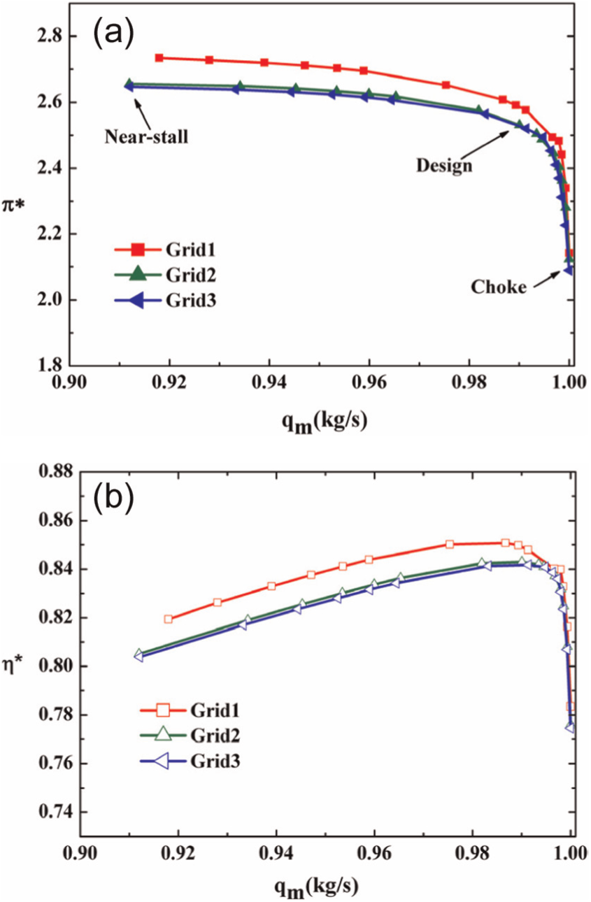
The performance characteristic of transonic contra-rotating axial compressor: (a) total pressure ratio and (b) efficiency.
Internal flow analysis and discussion
The shock-wave structure in TCRAC
Figure 5 shows the circumferentially averaged relative Mach number distribution on meridian plane, where the sound speed line (Ma = 1) is also highlighted. As seen from the figure, the relative velocity of the inlet of the second-stage rotor increases due to the reverse rotation, and the relative Mach number is greater than 1 along the entire blade height. At the choking point, the supersonic area in the whole flow field is large, especially around the Rotor 2, the sound speed line has reached 70% axial chord length, which indicates the existence of passage shock in the aft-half blade passage of the Rotor 2. It will be demonstrated later. At the design point, in the first rotor of TCRAC, the flow above the 35% of the blade height is the supersonic. The relative Mach number in the blade root region of the Rotor 2 inlet is larger than that at the middle and the tip regions of blade. At the near-stall point, the flow capacity of compressor is significantly reduced due to the increasing adverse pressure gradient along the flow direction. Among which, the flow of TCRAC working at near-stall condition is dominated by subsonic flows. The Rotor 2 blade tip area is blocked, and the sound speed line near the blade tip is pushed out of the blade passage. The overall trend of relative Mach number on the inlet two rotors is similar and the Mach number of middle blade is less than that of blade root and tip.

Circumferentially averaged relative Mach number distribution on meridian plane.
Figure 6 shows the relative Mach number distribution at 10%, 50%, and 90% blade height under different working conditions. It is noted that under the choking condition, a double shock structure appears in Rotor 2. In addition to the leading edge shock wave (LSW), there is another shock wave near the trailing edge of the blade, which is due to the low back pressure at the outlet. The airflow passing through the LSW is accelerated and expanded in the blade passage, and the shock wave is generated near the blade trailing edge by the disturbance of back pressure of the outlet. As the second shock wave is generated after the airflow expansion, there is no contribution to the pressure rise, and the intensity and loss are serious accordingly so that at the choking point, the efficiency of Rotor 2 is poor. Additionally, it can be seen from Figure 6 that even under the choking condition, the leading edge shock of Rotor 2 is in detached state.
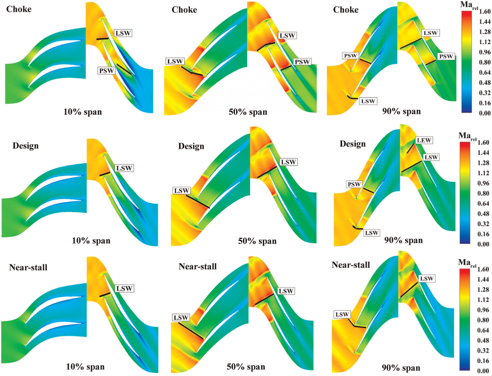
The Mach number contours at various blade span.
At the design point, in the blade root section, in view of the fact that the tangential velocity is low at the blade root section, there is no obvious shock wave produced in the first rotor passage except a local supersonic area on the suction surface about 10% of the axial chord. Due to the pre-swirl effect of the Rotor 1, the relative velocity of the Rotor 2 in the blade root of the inlet becomes supersonic. The supersonic flow produces a LSW, followed by uniform diffusion along the flow passage. In the middle blade section, Rotor 1 and Rotor 2 both show similar single shock-wave structure. The shock wave generated from the leading edge of rotor blade is further developing toward both sides. The right side of shock wave strikes the suction surface of the adjacent blade and becomes passage shock wave (PSW), which is the main source of the air pressurization. The left side of shock wave, influenced by the effect of expansion wave at the leading edge of blade, decays quickly and terminates at a free boundary in the fluid domain before the frontal line. Influenced by the outlet back pressure perturbation, the PSWs in two rotors are detached, which indicates that the load reaches the limitation. In the blade tip section, the shock-wave structure in Rotor 1 changes in essence that one normal and one oblique double shock-wave structure can be revealed. The shock-wave intensity at the leading edge of the blade (LSW) becomes weaken and curved. However, a strong PSW appears in the passage near the trailing edge of the blade. After passing through this positive shock wave, the supersonic flow becomes subsonic flow and decelerates outflow from the passage. Regarding Rotor 2, due to the modeling-making reason of the front part of blade suction surface, the airflow rapidly expands at this part, leading to a significant expansion wave at the leading edge of the passage. The expanded airflow will be compressed by PSW and hence increasing the pressure rise. Compared with the middle blade section, the PSW in the blade tip section is located farther away from the blade leading edge, indicating a greater adverse pressure gradient at the blade tip section, and the PSW is pushed further forward.
Under the near-stall conditions, the flow at the root shows a similar topology to that of the design condition, which indicates that the flow in blade root is not sensitive to the outlet back pressure. Moving to the mid-blade section, the LSW is stronger than that of design condition, farther from the leading edge of the blade, indicating that Rotor 1 and Rotor 2 are in high load status. At the tip section, the PSW of Rotor 1 is moved to the position of LSW and merged into one shock wave. The LSW of Rotor 2 also transfers upstream and the shape regularity becomes worse. It can be seen from Figure 6 that for all the three conditions, the shock-wave structure of Rotor 2 has varied more significantly than that of Rotor 1. Therefore, the following analysis focuses on the Rotor 2.
The flow characteristics analysis of TCRAC
As mentioned above, the Rotor 2 encounters supersonic flow along the full blade height. In order to further study the change of the subsequent flow characteristics of the Rotor 2, the limiting streamline on the blade surface of Rotor 2 is shown in Figure 7 under different conditions. At the choking point, the flow separation is prominent, particularly at the trailing edge of the suction surface (denoted as SS in Figure 7) of the blade root. Due to the presence of PSW near the trailing edge of blade, the adverse pressure gradient grows dramatically and hence causes separation. This separation occurs mainly on the suction surface, from 40% to 85% of the blade height. On the pressure surface (denoted as PS in Figure 7), the separation bubble near the root of blade is larger than that of other two working conditions. Moreover, the separation position further going to the tip and the blockage of the passage is aggravated. At the choking point, the separation on the suction surface (SS) and the pressure surface (PS) increases simultaneously and the total pressure loss is serious which leads to the lower efficiency.

The surface limiting streamline of Rotor 2 blade: (a) choke, (b) design, and (c) near-stall.
At the design point, it has a good flow condition on the suction surface of the blade and there are mainly two local separation areas. One is in the root region; the high-entropy and low-energy fluid has obvious radial migration tendency by the centrifugal force. Finally, the low-energy fluid accumulates near the trailing edge and separates under the action of the strong adverse pressure gradient. The second one is at about 40%–60% of the blade height where the shock waves interact with the boundary layer and a small-scale separation bubble emerges and reattaches quickly by the entrainment of high-speed mainstream. On the pressure surface, the airflow below the 15% of blade height was quickly separated after entering the blade passage, and there was a large-scale separation bubble. Extending by the airflow from high-blade area, this separation did not extend to the trailing edge of the blade and disappeared after about 75% of chord length.
Under near-stall condition, the flow near the blade root is improved. Although the radial migration range of the fluid at the root of the suction surface is larger than that of the design condition, the separation flow near the trailing edge is weakened. Additionally, the separation area near the root of the pressure surface nearly disappears, which helps improve the efficiency of the blade root zone. Because of the increase in shock-wave intensity, the separation bubble in the middle blade produced by the interaction between the shock wave and boundary layer expands in the flow direction and radial direction, leading to a larger loss. The flow around the blade tip deteriorates under near-stall condition rather than that of design condition. The through-flow capacity at the 50% chord length of the suction surface and the whole pressure surface are reduced obviously.
To accurately locate the source of the flow loss in the TCRAC, Figure 8 shows the entropy production rate distributions on the surface perpendicular to the streamwise direction (S3 surface) at the four axial chord lengths of the Rotor 2 under different conditions. Entropy production rate is defined as follows
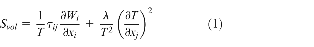
where the first term on the right side represents the viscous loss and the second term represents the heat dissipation loss. T is the static temperature,

Entropy production rate on S3 surface of Rotor 2 at various chord positions: 10% chord, 60% chord, and 90% chord.
To understand more about the reason of large flow loss that appears at the design and at the choking points in the root region of Rotor 2, but behave better at the near-stall point, a curved surface close to the pressure surface of blade is selected for analysis. As seen in Figure 9, the relative velocity streamline and axial velocity distribution under different working conditions are exhibited. From the choking condition to the near-stall condition, with the outlet back pressure rising, the axial pressure gradient grows up constantly but the axial velocity decreases, subsequently the separation area of blade root is also reduced. These indicate the larger pressure gradients are not the major cause of flow separation. It is considered that the design of the meridional flow passage has not matching well enough with the routing airflow parameters along the radial direction. Further optimization is needed in future. At the choking point, the smaller radial pressure gradient before the separation zone is not enough to overcome the larger radial flow momentum; the trend of streamline upward migration is clear. So, the airflow has no time to fill the space and separation occurs. As the back pressure increases, the negative effect caused by the enhanced tip leakage gradually increases. The range of low axial velocity in the blade tip extends continually in the radial direction, and the effective through-flow area of the meridional flow passage decreases. This unfavorable effect broke the radial flow equilibrium and the meridional streamline is extruded downward; thus, the flow separation zone is reduced as operating from choking condition to near-stall condition.

Relative velocity streamline and axial velocity on the surface close to pressure surface of Rotor 2 blade: (a) choke, (b) design, and (c) near-stall.
Figure 10 presents the three-dimensional streamline of the relative velocities in the blade roots of Rotor 2. The color of the streamlines denotes the velocity magnitude. Three flow passages are plotted and the blades are semitransparent. The vortex formation process can be seen clearly in this figure. The airflow in the front half of the blade passage is well, and the flow separation occurs close to the pressure surface side influenced by the hub profile, resulting in large-scale vortex and reduction of through-flow capacity of blade passage. Changing from the choking point to the near-stall point, as the back pressure increases, the separation vortex gradually decreases, and the blocking effect on the flow passage is reduced. At the design point and the choking point, the vortex constantly entrainments the surrounding fluid and induces the separation of the trailing edge of suction surface, which further reduces the through-flow capacity and increases the flow loss.

Three-dimensional streamline near the blade root of Rotor 2 under different operation conditions.
Conclusion
In this study, the shock-wave structure and flow characteristics of a transonic compressor under three typical operating conditions are numerically investigated. The conclusions are drawn as follows:
Under the three operating conditions, the shock-wave structure of the downstream rotor (Rotor 2) is more complex than that of the Rotor 1. Under the blocking condition, the double shock structure appears in the downstream rotor and the shock loss is serious. Under the design conditions, the single shock-wave structure appears in the root and middle of blade. But in the blade tip, one normal and one oblique shock wave exist. Under the near-stall condition, the shock wave in the blade root has not changed much. The detached shock wave in the middle blade is obvious and the tip shock wave moves further upstream.
When TCRAC works from the choke condition to the near-stall condition, as the load increases, the separation bubble size on the pressure surface of the Rotor 2 decreased gradually. At the design point, the separation on the suction surface is the minimum. The tip leakage flow becomes intense and the loss reaches the maximum level at the near-stall condition.
The design of the meridional flow passage of the downstream rotor and the degree of matching of the routing airflow parameters along the radial direction affect the flow separation in the passage, which will subsequently influence the compressor performance and need to be further optimized.
Footnotes
Academic Editor: Jose Ramon Serrano
Declaration of conflicting interests
The author(s) declared no potential conflicts of interest with respect to the research, authorship, and/or publication of this article.
Funding
The author(s) disclosed receipt of the following financial support for the research, authorship, and/or publication of this article: This work was supported by the National Science Foundation of China (nos 51506179 and 51376150) and the Fundamental Research Funds for the Central Universities (no. 3102016ZY018).