
Abstract
In order to investigate the internal flow characteristics and hydraulic stability of vertical submersible pump station in forward and reverse operation, the steady and unsteady three-dimensional numerical simulation of vertical submersible axial-flow pump device was carried out based on CFD and the energy performance of the pump device was predicted. In this paper, the internal flow characteristics of the vertical submersible axial-flow pump device under forward and reverse operation were analyzed, and the optimization of the structure passed by water was carried out to improve the efficiency of the pump device in forward and reverse operation. The results show that the performance of the pump device is good when it is running in the forward direction, the peak efficiency of the pump device is 72.22% and the corresponding head is 4.01 m. When it is running in the reverse direction, the performance of the pump device decreases significantly with the peak efficiency is only 36.03% and the corresponding head is 3.34 m. The hydraulic loss in the dust-pan-shaped conduit is very small in the forward operation, the wellbore conduit is the main factor which affects the efficiency of the submersible axial flow pump device, the loss ratio is 12%–44%. When the pump device is in reverse operation, the hydraulic loss is similar but the hydraulic performance is poor and the hydraulic loss is obviously larger than that in forward operation. A guide plate is added to the dust-pan-shaped conduit at 0.27D (D is the nominal diameter of impeller) along the axis direction of the conduit, and a elbow flow conduit with the corner radius R of 0.83D is selected to replace the wellbore conduit, the bad flow state disappeared and the efficiency of the pump device increased by 5.19% in the forward operation while the efficiency of the pump device increased by 9.62% in the reverse operation.
Keywords
Introduction
Vertical submersible axial flow pump compared with the traditional axial flow pump has many advantages, such as safe and simplified structure, stable operation, low noise, no temperature rise, and convenient maintenance and is very suitable for urban drainage and sewage. Compared with the one-way submersible pump device, the bidirectional submersible pump device has the advantages of meeting the needs of urban flood control and improving the function of urban river water environment. At present, some built urban vertical axial flow pumping stations need to change from one-way pumping function to bidirectional pumping function. However, a large amount of civil engineering investment needs to be increased in the reconstruction of vertical pumping stations. The change of hydraulic structure also pre-embed safety risks for the safe and stable operation of the pumping station in the later stage. On the basis of little change in the original one-way flow conduit, it is feasible and economical to use the S-shaped reversible impeller to realize the reverse pumping function of the pumping station. For example, the modified pump device of Mudu Port Pumping Station of Suzhou River Environmental Comprehensive Improvement Project in Jiangsu Province of China consists of a submersible pump with an S-shaped reversible impeller, a dust-pan-shaped inlet conduit and a volute-type outlet conduit; The pump station of Zhenjiang Approach Channel Water Conservancy Project in Jiangsu Province of China adopts S-shaped reversible impeller, elbow inlet conduit and straight elbow outlet conduit, and realizes the forward and reverse operation of the pump station through the forward and reverse rotation of the pump. Therefore, the operation stability of vertical axial flow pump device with unidirectional flow conduit in forward and reverse operation and the optimization of the structure of vertical submersible axial flow pump device in reverse operation are worthy of attention. Vertical axial flow pump is widely used, many domestic and foreign scholars have carried out a lot of research, such as: Meng et al. 1 explored the influence of blade root clearance on the hydraulic performance of bidirectional axial flow pump under forward and reverse operating conditions under different flow rates. Wang et al. 2 explored the method to effectively suppress the hump area of axial flow pump characteristic curve. Yuan et al. 3 studied the influence of impeller and guide vane matching on the hydraulic performance of high specific speed axial flow pump. Zhang et al. 4 conducted the clearance leakage flow experiment and numerical calculation analysis of axial flow pump to study the formation and evolution mechanism of tip leakage vortex (TLV) of axial flow pump, and the influence of cavitation conditions and clearance width of vortex formation. Zhao et al. 5 proposed a scheme of arranging discontinuous bulge structure on the back of axial flow pump blade to control the occurrence and development of axial flow pump cavitation. Chen et al. 6 investigated the vibration and noise induced by unsteady flow in an axial-flow pump. Dai et al. 7 researched the characteristics of pressure pulsation of axial flow pumps under different runaway conditions. Feng et al. 8 proposed a developed alternative numerical model based on an alternative truncated Rayleigh-Plesset equation and the homogeneous flow assumption. Jianjun Feng et al. 9 investigated the influence of tip clearance on pressure fluctuations in an axial flow water pump. Kan et al. 10 studied the dynamic stress improvement of an axial-flow pump and validated the simulation results with a prototype test. Kan et al. 11 used 3D computational fluid dynamic (CFD) technology to study the rotating stall flow characteristics of an axial-flow pump. Lin et al. 12 did the experiment on the internal flow field of the pump with the method of CFD to study the effect of sediment on the cavitation in the axial-flow pump. Mu et al. 13 proposed a new groove flow control technology for the axial flow pump and studied its improvement effect and mechanism under stall conditions by numerical simulation. Shen et al. 14 introduced the entropy generation theory to study mechanical energy dissipation with varying discharge and tip clearance intuitively through numerical simulations in an axial-flow pump. Shervani-Tabar et al. 15 studied the cavitation performance of an axial flow pump is monitored based on vibration signals. Shi et al. 16 designed an axial-flow pump impeller on the basis of plane cascade theory to study the influence of impeller rotor on the hydraulic performance of the a full tubular pump. Song et al. 17 investigated the pressure pulsation induced by the floor-attached vortex in an axial flow pump. Svoboda et al. 18 analyzed the flow of viscous liquid in highly efficient commercial axial pumps. Yang et al. 19 used the time–frequency domain analysis method to analyze the pressure pulsation of each flow structure of the 30° slanted axial-flow pump device. Yang et al. 20 studied the influence of different deflection angles on the internal flow characteristics and outlet pulsation characteristics of the inlet passage of the vertical axial flow pump. Yang et al. 21 studied the variation law of the flow field and pressure fluctuation in the hump section of the siphon outlet conduit under the conditions of the interaction between the axial flow pump and siphon outlet conduit. Zhang et al. 22 investigated the tip leakage flow structure and instantaneous evolution of tip vortex cavitation in a scaled axial-flow pump model. Zhang et al. 23 investigated the influence of the evaluation criteria of inlet flow conditions and numerical grid scales on the accuracy of the simulation based on two axial-flow pump devices. Zhou et al. 24 studied the hydraulic characteristics of large vertical axial-flow pump used as constant frequency power generation. Zhou et al. 25 selected double-inlet design to improve the operational characteristics of an axial-flow pump under low flow rate conditions. Currently, scholars have carried out more research work on axial flow pump and have obtained many research results. The existing research results also provide reference methods and analysis ideas for this study. In order to solve the current problem of low efficiency and poor stability of vertical submersible axial flow pump in bidirectional operation, it is necessary to analyze the internal flow mechanism of vertical submersible axial flow pump device. In this paper, the hydraulic performance of vertical submersible axial flow pump device was predicted by numerical simulation method, and the internal flow characteristics of each flow structure of vertical submersible axial flow pump device in forward and reverse operation were analyzed. According to the analysis results, the flow structure of the pump device is optimized, which provides reference for the optimization design and efficient, safe and stable operation of vertical submersible axial flow pump device.
Model and calculation method of pump device
Calculation model and parameters
The vertical submersible axial flow pump device is composed of four flow passage components: dust-pan-shaped flow conduit, reversible impeller, guide vane, and wellbore flow conduit. The three-dimensional model of the pump device is shown in Figure 1. The reversible impeller is designed with “S” wing shape. The number of blades is 3, the blade placement angle is 0°, the hub ratio is 0.4, the tip clearance of the impeller is set to 0.1 mm, the impeller speed is 1450 r/min, the guide vane is the diffusion guide vane, the equivalent diffusion angle of water flow in the guide vane is 10°, and the number of blades is 5. Based on the nominal diameter D of the impeller, the main geometric dimensions of the dust-pan-shaped flow conduit, and the wellbore flow conduit are dimensionlessly converted. The main geometric dimensions of the conduit are shown in Figure 2. The dust-pan-shaped flow conduit is 5.28D long, 3.2D wide, and 2.17D high. The height of wellbore flow conduit is 3.33D, the diameter of wellbore is 1.35D, the motor length is 1.37D, and the diameter is 0.58D.

Three-dimensional model of vertical submersible axial flow pump device.

Main geometric dimensions of conduit: (a) dust-pan-shaped flow conduit and (b) wellbore flow conduit.
When the vertical submersible axial flow pump device is running forward, the water works through the impeller from the dust-pan-shaped flow conduit to the wellbore flow conduit, and the operation mode is shown in Figure 3(a). When the vertical submersible axial flow pump device runs reversely, the water reverses through the impeller to work from the wellbore flow conduit into the dust-pan-shaped flow conduit, and the operation mode is shown in Figure 3(b).

Bidirectional operation diagram of pump device: (a) forward operation and (b) reverse operation.
Numerical methods and boundary conditions
It is assumed that the medium transported by the vertical submersible axial flow pump device is incompressible liquid, and the flow in the pump device is three-dimensional unsteady turbulent flow, which follows the governing equations based on the N-S equation. 26 In this paper, the RNG k-ε model that can better deal with the flow with high strain rate and large streamline curvature is applied to the numerical simulation of the pump device. The turbulent model is proved to be very suitable for the simulation of the flow field in the pump and pump device.27–29 The mass flow inlet boundary condition is adopted at the inlet of the dust-pan-shaped flow conduit extension section, and the pressure outlet boundary condition is adopted at the outlet of the wellbore flow conduit extension section. The non-slip wall is used in the solid wall, and the Scalable wall function is used in the near wall. The convergence accuracy is set to 1.0 × 10⁻⁵. The interface is connected by the GGI method, which allows the grid types on both sides of the interface to be different, and the nodes are not one-to-one correspondence, so it has strong adaptability. The impeller calculation domain is a rotating calculation domain, and the interface with the inlet calculation domain and the guide vane calculation domain belongs to the dynamic and static interface. There is a coordinate system transformation on both sides of the interface. Stage interface is used in steady calculation, and Transient Rotor Stator interface is used in unsteady calculation. The interface between the calculation domain of the water flow extension section and the calculation domain of the dust-pan-shaped flow conduit, the interface between the calculation domain of the guide vane and the calculation domain of the wellbore flow conduit belong to the static interface. There is no coordinate system transformation on both sides of the interface, and the None interface model is adopted. In the unsteady three-dimensional numerical simulation of the vertical submersible axial flow pump device, the data are saved once every 3° rotation of the impeller. In order to stabilize the simulation results of the unsteady flow field and control the calculation amount, eight impeller rotation cycles are calculated in this study. According to the rotation speed of the pump device, the time length of 3° rotation of the impeller is 0.000344 s, and the total time length of eight circles is 0.331 s.
Mesh independence and convergence analysis
The dust-pan-shaped flow conduit and wellbore flow conduit are structured meshed by ICEM CFD. The specific process is: the three-dimensional models of the dust-pan-shaped flow conduit and the wellbore flow conduit are imported into the ICEM CFD software, and each part of the model is named. The block approximation geometric model is established until the built block corresponds to each part of the model. By mapping the relationship between points, lines and surfaces, the consistency of the model and the built block structure is ensured, and the O-Block operation is performed on the built block to ensure the quality of the wall boundary layer grid of the model. The impeller and guide vane are divided into structured grids by Ansys Turbo-Grid, and the hexahedral structured grids are automatically generated by ATM optimization method. The grid quality is adjusted by adding topology and adjusting grid parameters. The grid of each component is shown in Figure 4.
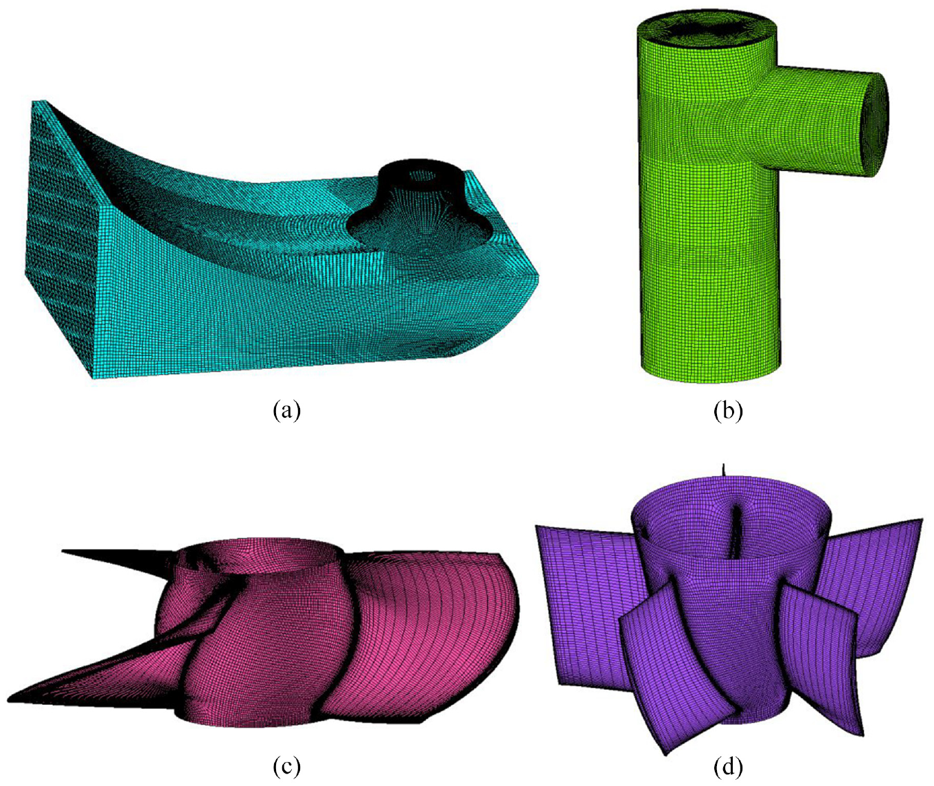
Wall grid diagram of vertical submersible axial flow pump device: (a) dust-pan-shaped flow conduit, (b) wellbore flow conduit, (c) impeller, and (d) guide vane.
In order to select the appropriate number of computational grids and improve the calculation efficiency under the condition of ensuring the calculation accuracy, the independence of the number of grids in the computational domain of the vertical submersible axial flow pump device is analyzed. By adjusting the number of structured grid nodes to continuously increase the number of grids, six sets of pump device models with different grid numbers are obtained, and the grid numbers are 1523455, 2234480, 3129080, 4003213, 5443241, and 8093453, respectively. The corresponding grid calculation schemes are 1–6. The rationality of the grid is judged by the pump device efficiency and the absolute difference between pump device efficiency. When the pump device efficiency changes little and the absolute difference between the pump device efficiency is small, the grid number is reasonable. The analysis results are shown in Figure 5.

Pump device efficiency curve with different numbers of grids and efficiency difference.
The absolute difference formula of pump device efficiency is:

Where ηa is the absolute difference of pump device efficiency, i, j is the mesh number, i = 1,2,…, 5, j = i+1.
It can be seen from Figure 5 that with the increase of grid number, the device efficiency gradually tends to be stable. When the number of grids increases to 5.44 million, the absolute error of device efficiency in schemes 5 and 6 does not exceed 0.2%, meeting the accuracy requirements.8,12
The grid convergence index GCI (Grid Convergence Index) is introduced to verify the grid convergence of each scheme. 30 The calculated grid convergence index is shown in Table 1.
Analysis of grid convergence index.
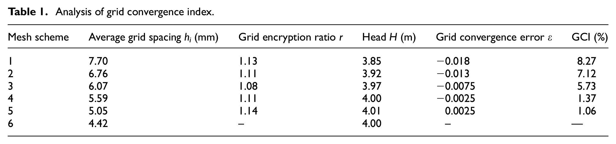
It can be seen from Table 1 that the grid convergence indexes GCI of Scheme 4 and Scheme 5 are less than 3%, which satisfies the grid convergence criterion. Combined with the grid independence analysis, Scheme 5 is finally selected as the calculation scheme. The number of grids in the dust-pan-shaped flow conduit is 1152612, and the mean value of y+ is 162.52. The grid number of impeller is 1495440, and the mean y+ is 45.35. The mesh number of guide vane is 915600, and the mean value of y+ is 65.43. The grid number of wellbore flow conduit is 729856, and the average y+ is 120.32. The y + value of each flow component meets the requirements of numerical simulation proposed in Wang. 31
Energy performance prediction of pump device
Based on the three-dimensional unsteady numerical calculation results of the pump device, the energy performance of the vertical submersible axial flow pump device in forward and reverse operation is predicted. In order to facilitate the analysis, the flow coefficient 26 is introduced to obtain the energy performance curve of the pump device (Figures 6 and 7). In the forward operation, when the flow coefficient K Q = 0.536, the efficiency of the pump device reaches the maximum, and the efficiency is 72.22% and the head is 4.01 m. In the reverse operation, the pump device operates efficiently when K Q is between 0.321 and 0.429. When the flow coefficient K Q = 0.368, the efficiency of the pump device reaches the maximum, the maximum efficiency is only 36.03%, and the corresponding head is 3.34 m. The efficiency of vertical submersible axial flow pump device in forward operation is much higher than that in reverse operation.
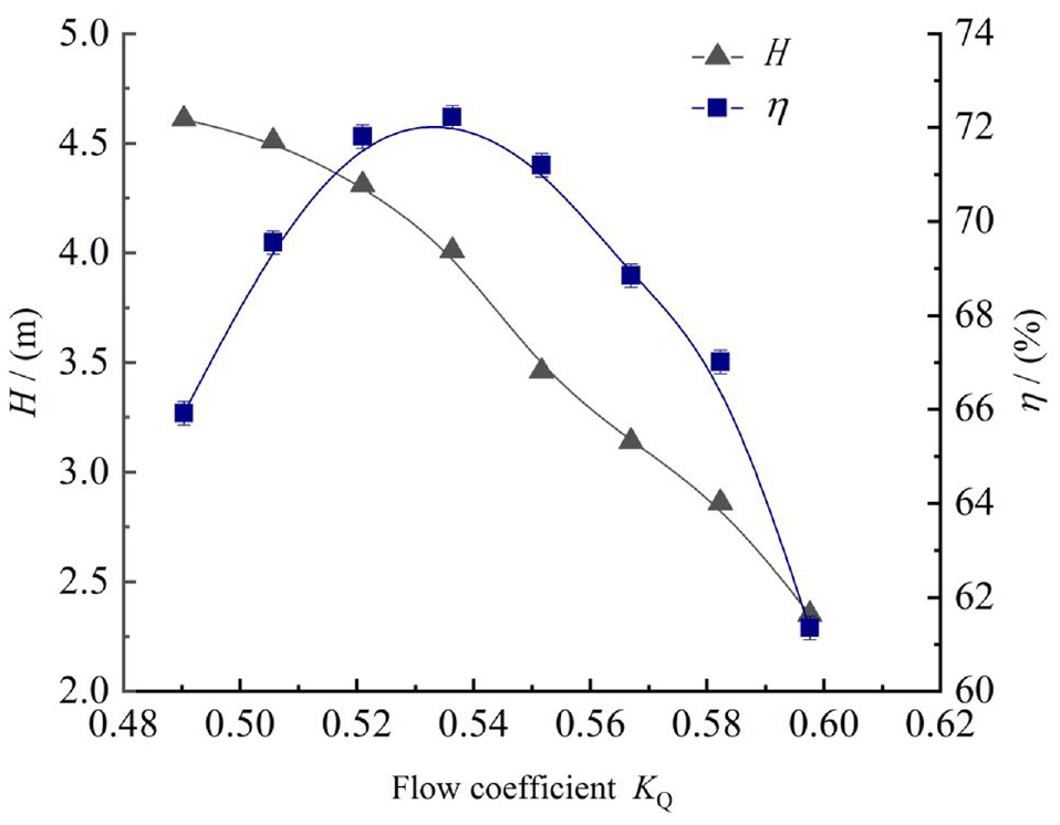
Pump device energy performance curve (forward operation).
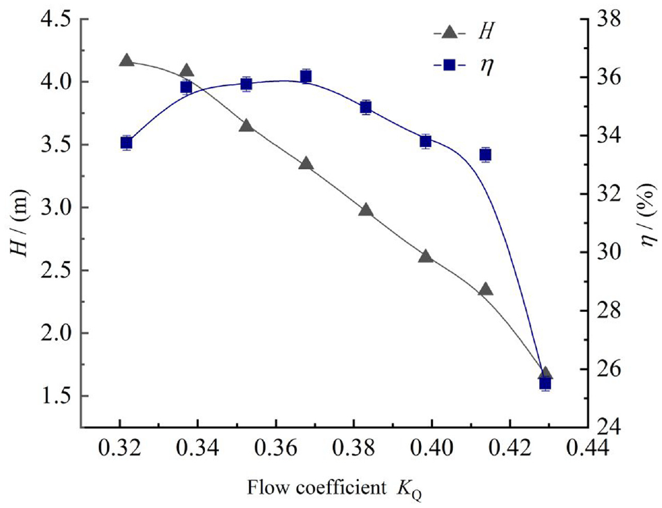
Pump device energy performance curve (reverse operation).
Internal flow mechanism analysis of pump device
Forward flow characteristics analysis of pump device
In different flow conditions, the three typical conditions of small flow condition K Q = 0.490, high efficiency condition K Q = 0.536 and large flow condition K Q = 0.583 are taken for analysis. The flow lines in the whole conduit of the pump device are shown in Figure 8. Under different flow conditions, the internal streamlines of the dust-pan-shaped flow conduit are smooth, and the velocity circulation of the water flow is large after passing through the impeller chamber, resulting in the disorder of the internal streamlines of the wellbore flow conduit. Under the three flow conditions, the internal flow pattern of the wellbore flow conduit is relatively disordered, and the swirling flow is generated at the top of the conduit.

Internal flow line of pump device (forward operation): (a) K Q = 0.490, (b) K Q = 0.536, and (c) K Q = 0.583.
Analysis of internal flow characteristics in forward-flow dust-pan-shaped flow conduit
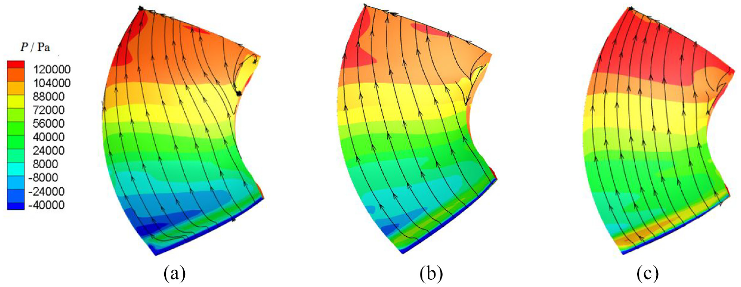
The flow field distribution at the outlet of the dust-pan-shaped flow conduit has a great influence on the operation efficiency of the impeller. Figure 9 shows the streamlines and pressure contours of the central longitudinal section of the dust-pan-shaped flow conduit under three flow conditions. The pressure distribution inside the dust-pan-shaped flow conduit gradually decreases from the inlet to the outlet under different flow conditions. With the increase of flow rate, the pressure at the same position inside the dustpan-shaped flow conduit increases. The pressure at the outlet surface of the dust-pan-shaped flow conduit is basically symmetrically distributed, and the velocity distribution is relatively uniform. Under different flow conditions, the internal streamline of the dust-pan-shaped flow conduit is smooth and straight, and no obvious vortex is observed.

Flow line and pressure distribution of dust-pan-shaped flow conduit (forward operation): (a) K Q = 0.490, (b) K Q = 0.536, and (c) K Q = 0.583.
Internal flow characteristics of impeller and guide vane in forward operation
The friction line and contours of pressure on the pressure surface of the impeller are shown in Figure 10. The pressure of the pressure surface of the impeller blade under different flow conditions decreases from the inlet side to the outlet side of the impeller. The pressure distribution of the pressure surface of the impeller blade under different flow conditions is less affected by the flow, and the distribution is basically the same. On the pressure surface of the impeller blade, the distribution of the friction line on the blade surface is relatively straight. There is a certain backflow at the outlet side of the pressure surface of the impeller under each flow condition, and there is an obvious backflow at the outlet side of the blade under small flow condition (K Q = 0.490) and large flow condition (K Q = 0.583). The friction line and contours of pressure on the impeller suction surface are shown in Figure 11. The friction line of the impeller blade suction surface is relatively straight. The pressure of the blade suction surface increases from the inlet side to the outlet side under different flow conditions, and the impeller blade suction surface increases with the increase of flow rate.

The friction line and contours of pressure on the pressure surface of the impeller (forward operation): (a) K Q = 0.490, (b) K Q = 0.536, and (c) K Q = 0.583.
The friction line and contours of pressure on the suction surface of the impeller (forward operation): (a) K Q = 0.490, (b) K Q = 0.536, and (c) K Q = 0.583
The three-dimensional flow field inside the diffuser guide vane under different flow conditions is shown in Figure 12. Under each flow condition, the flow line inside the guide vane is relatively straight as a whole. Due to the difference in the flow velocity part under each flow condition, the vortex and backflow appear on the back of the guide vane. Under the small flow condition (K Q = 0.490), the vortex range on the back of the guide vane is large. Under the high efficiency condition (K Q = 0.536), the vortex is significantly reduced. Under the large flow condition (K Q = 0.583), the vortex on the back of the guide vane completely disappears, mainly because the velocity circulation at the impeller outlet is small under the large flow condition and the influence of transverse flow velocity on the mainstream is weakened, which leads to smooth streamline in the guide vane.

Three-dimensional flow field diffusion guide vane (forward operation): (a) K Q = 0.490, (b) K Q = 0.536, and (c) K Q = 0.583.
Flow characteristics of positive inflow wellbore flow conduit
The streamline and pressure contours of wellbore flow conduit are shown in Figure 13. Under different flow conditions, the pressure inside the wellbore flow conduit gradually increases from the bottom to the top of the conduit, and the pressure at the top of the conduit decreases to the outlet of the conduit. The pressure at the top of the wellbore flow conduit reaches the maximum, and the pressure in the area below the outlet pipe reaches the minimum. Under different flow conditions, the streamline distribution inside the wellbore flow conduit is disordered, and the streamline inside the flow conduit gradually becomes straight with the increase of flow rate. There are a large range of vortexes and backflows in the high pressure area at the top of the wellbore flow conduit and the low pressure area inside the outlet pipe. The backflow area at the top of the wellbore also increases with the increase of flow rate. The vortex at the outlet pipe develops into two small vortexes with the increase of flow rate and gradually decreases. The backflow area further expands and affects the outflow flow pattern.

Flow line and pressure contours of wellbore flow channel (forward operation): (a) K Q = 0.490, (b) K Q = 0.536, and(c) K Q = 0.583.
Analysis of reverse flow characteristics of pump device
In the reverse operation of the vertical submersible axial flow pump device, the internal flow analysis is carried out under the small flow condition (K Q = 0.322), the high efficiency condition (K Q = 0.368), and the large flow condition (K Q = 0.414). The overall streamline diagram of the vertical submersible axial flow pump device under three flow conditions can be seen in Figure 14. The streamline morphological characteristics inside the inlet and outlet channels under different flow conditions are similar. The fluid flows into the wellbore from the outlet pipe of the wellbore flow conduit, impacting the inner wall of the wellbore to form a large-scale vortex around the fluid, and the streamline density on the left side of the wellbore flow conduit is significantly greater than that on the right side, indicating that the flow distribution in the cross section of the conduit is uneven. Inside the dust-pan-shaped flow conduit, it can be seen from the streamline shape below the impeller that the fluid has a large velocity circulation and a large velocity. When it enters the bottom of the dust-pan-shaped flow conduit, the impact occurs, and a large range of vortexes are distributed in the whole flow field. In addition, the streamline gradually tends to be straight from the bottom of the impeller to the inlet of the dust-pan-shaped flow conduit.

Internal flow line of pump device (reverse operation): (a) K Q = 0.322, (b) K Q = 0.368, and (c) K Q = 0.414.
Analysis of internal flow characteristics of reverse operation dust-pan-shaped flow conduit
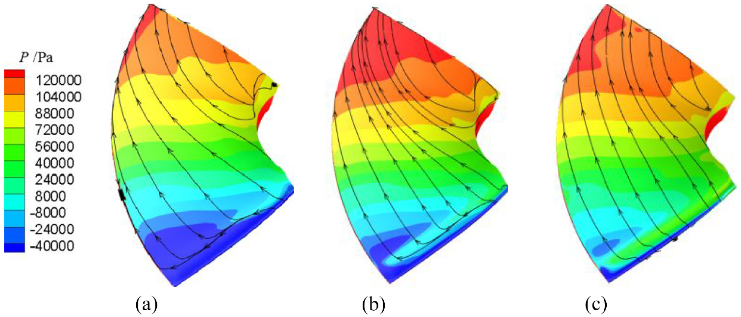
It can be seen from Figure 15 that when the pump device is in reverse operation, the pressure distribution in the dust-pan-shaped flow conduit varies little under different flow conditions. Under different flow conditions, the pressure changes in the region below the impeller in the conduit are large, and the pressure values in other regions are similar. The vortex center at the impeller outlet is a low-pressure region, and the high-pressure region is mostly distributed on the conduit wall. The streamline distribution in the dust-pan-shaped flow conduit is very disordered. At each flow condition, vortices are formed near the water guide cap, and a large-scale backflow zone is formed below the impeller, and the flow pattern is poor.

Flow line and pressure distribution of dustpan-shaped flow conduit (reverse operation): (a) K Q = 0.322, (b) K Q = 0.368 and (c) K Q = 0.414.
Internal flow characteristics of impeller and guide vane in reverse operation
In reverse operation, the working face of impeller blade is opposite to that in forward operation. As shown in Figure 16, there is little difference in the pressure distribution of the suction surface of the impeller blade under three different flow conditions. The pressure at the inlet side of the blade is the lowest under the same flow condition, and the pressure increases gradually from the inlet side to the outlet side of the blade. With the increase of flow rate, the surface pressure of blade suction surface gradually increases. The friction lines on the suction surface of impeller blade are relatively straight, but there is a partial flow phenomenon on the friction line at the hub of blade outlet edge, and the smaller the flow rate is, the more obvious the partial flow phenomenon is. The pressure distribution of impeller blade pressure surface is shown in Figure 17. The pressure at the inlet edge of impeller blade pressure surface gradually decreases from the flange to the hub, and the pressure gradually decreases from the inlet edge to the outlet edge. The pressure distribution of the pressure surface of the blade under different flow conditions is obviously different in the local area. There is a large low pressure area near the outlet edge of the blade under small flow condition and large flow condition, and the pressure at the hub of the blade under small flow condition is larger. There are different degrees of backflow on the pressure surface of the impeller blade. The smaller the flow rate, the more obvious the backflow on the blade surface.
The friction line and contours of pressure on the suction surface of the impeller (reverse operation): (a) K Q = 0.322, (b) K Q = 0.368, and (c) K Q = 0.414.

The friction line and contours of pressure on the pressure surface of the impeller (reverse operation): (a) K Q = 0.322, (b) K Q = 0.368 and (c) K Q = 0.414.
The three-dimensional flow field of the guide vane is shown in Figure 18. In reverse operation, the guide vane is changed from rear to front, and the velocity circulation of the fluid cannot be recovered, and the fluid is more disordered due to the influence of the arc on the back of the guide vane. Considering the special situation of the diversion caused by the change of the original wellbore flow conduit into the inlet flow conduit, the front guide vane still has a certain rectification effect on the fluid. The three-dimensional flow field streamline diagram of the diffusion guide vane is obtained by post-processing. It is observed that the streamline distribution at the guide vane is similar under different flow conditions, which is more uniform and no backflow phenomenon. When the streamline enters the guide vane from above, the deflection is obvious, and the guide vane blade has certain improvement.

Three-dimensional flow field diffusion guide vane (reverse operation): (a) K Q = 0.322, (b) K Q = 0.368 and (c) K Q = 0.414.
Flow characteristics of reverse inflow wellbore flow conduit
The flow line and pressure contour of reverse operation wellbore flow conduit are shown as Figure 19. The pressure distribution of the wellbore flow conduit under different flow conditions shows that the pressure from the water pipe to the top of the wellbore increases gradually, and the pressure from the top to the bottom of the wellbore decreases gradually. The pressure at the wellbore wall of fluid impact is the largest, and the pressure above the submersible motor is the lowest. Under different flow conditions, the streamlines in the wellbore tube are straight and evenly distributed, but after entering the wellbore and impacting the wellbore wall, a large range of vortices are formed above the wellbore, and the backflow is formed on the right side of the motor. As the flow rate increases, the area above the motor forms a vortex.

Flow line and pressure contour of wellbore flow channel (reverse operation): (a) K Q = 0.322, (b) K Q = 0.368 and(c) K Q = 0.414.
Analysis of hydraulic performance parameters of pump device
Analysis of axial velocity distribution uniformity and weighted average angle of characteristic section
In order to analyze the inflow conditions of the submersible axial flow pump device and the adjustment effect of the diffusion guide vane on the flow field, three sections of the impeller inlet region, the middle region of the impeller and the guide vane and the outlet region of the diffusion guide vane were selected. The axial velocity distribution uniformity and the velocity weighted average angle 26 were used to quantitatively analyze the hydraulic performance parameters of the three different sections. The characteristic sections are shown in Figure 20.

Schematic diagram of each characteristic section.
The calculation formula of axial velocity distribution uniformity is:

The calculation formula of velocity weighted average angle is:

Where Vau is the uniformity of axial velocity distribution,
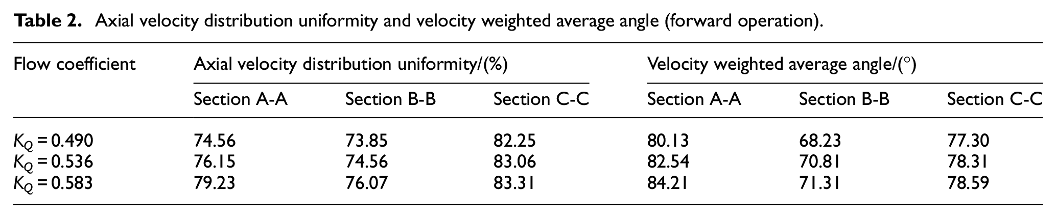
The calculation results of axial velocity distribution uniformity and velocity weighted average angle of different sections under positive operation are shown in Table 2. With the increase of flow rate, the axial velocity distribution uniformity and velocity weighted average angle of each section increase. The axial velocity distribution uniformity and velocity weighted average angle of section C-C at impeller inlet are the largest, which indicates that the dust-pan-shaped flow conduit has good hydraulic performance. After the fluid flows out from the impeller, the circulation is large and the flow pattern becomes worse, resulting in a large decrease in the uniformity of section B-B axial velocity distribution and velocity weighted average angle at different flow conditions. Since the guide vane has the effect of diversion and elimination of circulation, the axial velocity distribution uniformity and the weighted average angle of velocity and velocity of section A-A under different flow conditions are greater than those of section B-B.
Axial velocity distribution uniformity and velocity weighted average angle (forward operation).
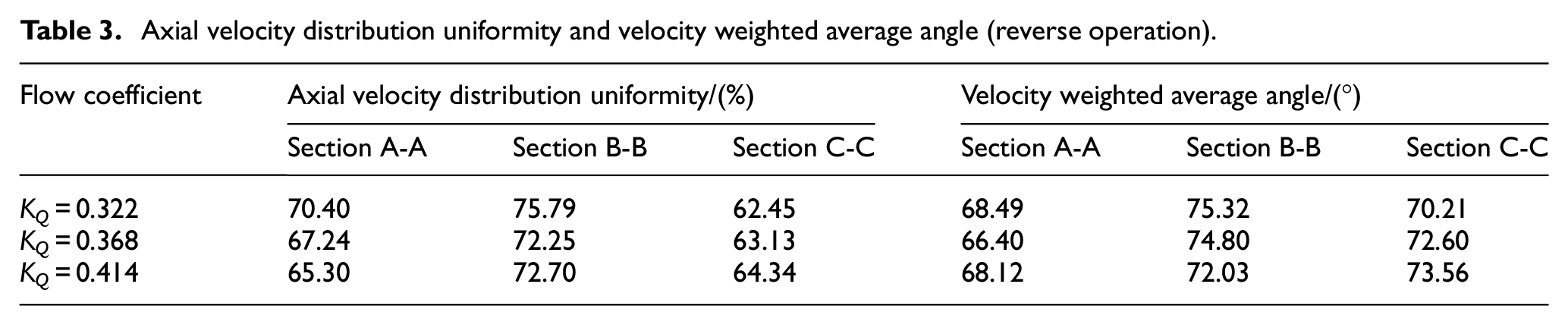
In reverse operation, the performance of axial velocity distribution uniformity and velocity weighted average angle of each section is relatively poor, as shown in Table 3. In addition to section C-C, when K Q = 0.322 in small flow condition, the axial velocity distribution uniformity and velocity weighted average angle of each section are greater than those in other flow conditions. Due to the change of wellbore flow conduit into inlet flow conduit, when the flow rate increases, the deviation flow is more serious, and the influent condition of reverse operation is worse. The axial velocity distribution uniformity and velocity weighted average angle of section B-B are greater than section A-A under different flow conditions. It indicates that the guide vane has a certain improvement effect on the adverse flow pattern in the inflow under reverse operation.
Axial velocity distribution uniformity and velocity weighted average angle (reverse operation).
Average velocity circulation analysis of effluent structure
Due to the effect of circulation, the flow pattern in the flow conduit is not good, which seriously affects the performance of the pump device. In order to explore the circulation changes in the outlet flow conduit under different flow conditions, when the pump device is running forward, three sections are selected in the wellbore flow conduit to calculate the average velocity circulation. When the pump device is running backward, two sections at the impeller outlet and below the flare tube are selected in the dust-pan-shaped flow conduit to calculate the average velocity circulation. 32 The calculation of the average velocity circulation is shown in formula (4). The schematic diagram of the section is shown in Figure 21. The impeller inlet section D-D is selected, and the distance between section E-E and D-D is D; the impeller outlet section A-A is selected, the distance between section B-B and A-A is 0.9D, and the distance between section C-C and A-A is 1.9D; the D-D distance of impeller centerline to section is 0.15D.


Characteristic section position diagram: (a) forward operation and (b) reverse operation.
Where Γ is the average velocity circulation in m2/s, L1and L2 represent impeller rim boundary and hub boundary respectively, R1 and R2 respectively represent the radius of flange boundary and hub boundary of impeller outlet section in m, vt is tangential velocity of flow in fluid section in m/s,
It can be seen from Figure 22 that when the flow condition is K Q = 0.322, the average velocity circulation of section A-A reaches the maximum value, and the average velocity circulation decreases with the increase of flow rate. At the same time, the farther away from the impeller, the smaller the average velocity circulation is. Figure 23 shows the average velocity circulation of the dust-pan-shaped flow conduit under the reverse operation of the pump device. Under the reverse operation of the pump device, the flow rate under the high efficiency condition is less than that under the forward operation, and there is no recovery of the velocity circulation by the guide vane, resulting in a large circulation at the outlet of the impeller. When the flow coefficient is 0.32, the average velocity circulation of the section D-D reaches the maximum value, which is 1.54 times that under the forward operation. This is because there are many vortices in the flare tube, and the cross section area below the flare tube is large, resulting in a relatively small average velocity circulation.

Average velocity circulation of wellbore flow conduit (forward operation).

Average velocity circulation of dust-pan-shaped flow conduit (reverse operation).
Analysis of hydraulic loss
In order to further analyze the variation of hydraulic loss under different flow conditions, the hydraulic loss ratio K is defined as the ratio of hydraulic loss to pump device head. In forward operation, dust-pan-shaped flow conduit is the inlet flow conduit, and wellbore flow conduit is the outlet flow conduit; in reverse operation, the dustpan-shaped flow conduit is the outflow flow conduit, and the wellbore flow conduit is the inlet flow conduit. The hydraulic loss of the dustpan-shaped channel and the wellbore flow conduit is shown in Figure 24. The hydraulic loss of the dust-pan-shaped flow conduit increases with the increase of the flow rate, and the change is more regular. The hydraulic loss of wellbore flow conduit increases with the increase of flow rate. The hydraulic loss is mainly composed of circulation loss and local head loss. When the flow rate is small, the circulation loss accounts for a large proportion. When the flow rate is large, the flow rate increases, and the frictional head loss and local head loss increase. There is a large range of backflow area at the top of the wellbore and the outlet pipe, and the head loss is large. The wellbore flow conduit has a great influence on the overall efficiency of the pump device. In the range of flow coefficient K Q = 0.460–0.613, the hydraulic loss ratio of the wellbore flow conduit is the lowest 12.0% and the highest 43.83%. In the reverse operation of the pump device, the hydraulic loss is similar to that in the forward operation, but the hydraulic performance is poor, and the hydraulic loss is significantly greater than that in the forward operation. In addition, the proportion of hydraulic loss in the dust-pan-shaped flow conduit increases with the increase of flow rate.
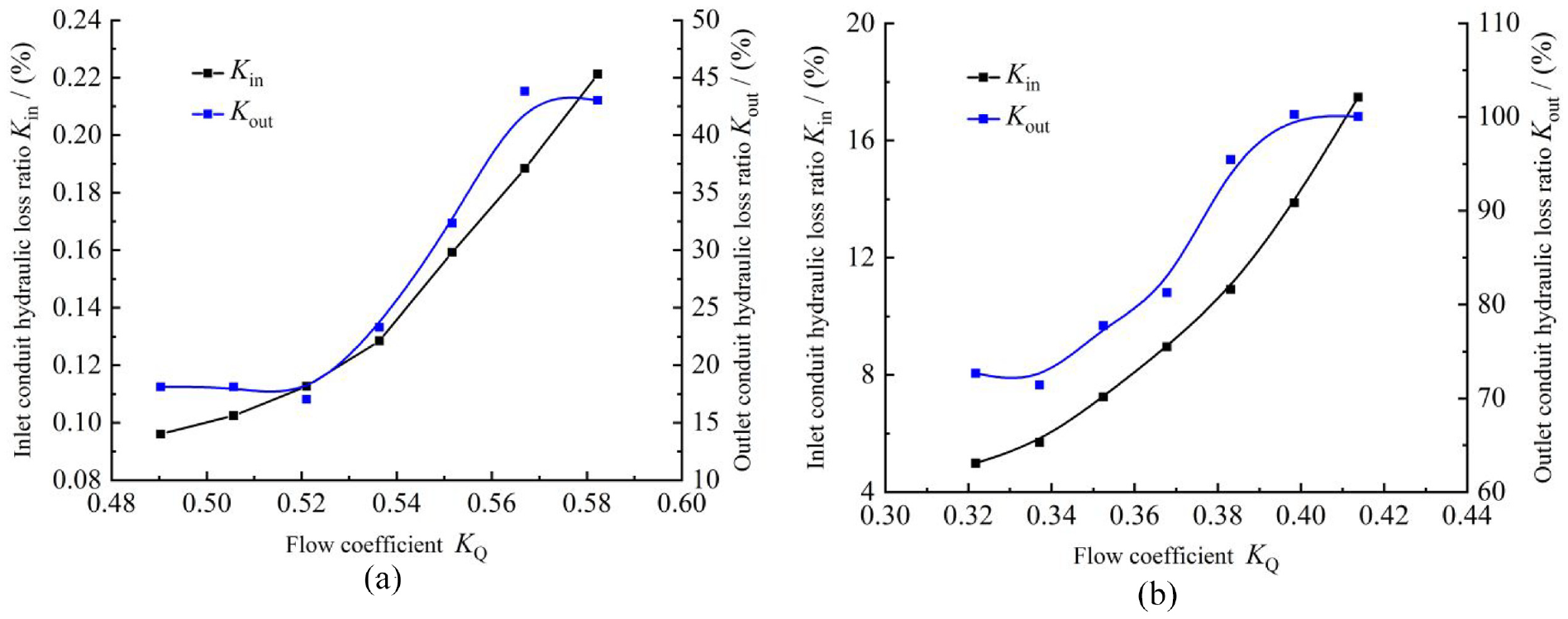
Flow channel hydraulic loss ratio: (a) forward operation and (b) reverse operation.
Internal vortex morphology evolution of pump device outlet structure
When the vertical submersible axial flow pump device runs in the positive direction, the fluid still has a large circulation after flowing through the guide vane. The structural characteristics of the top of the wellbore make a large number of vortexes in the region and inside the outlet pipe. In the identification method of vortex morphology, there are mainly pressure isosurface method, Q criterion and λ2 criterion, Ω vortex criterion and Liutex vortex vector method. Q criterion and λ2 criterion have stronger ability to capture vortex morphology comparatively, and can clearly and reasonably display vortex morphology, so as to capture the internal flow characteristics and the development characteristics of vortex morphology in the water pipe more intuitively. In this study, based on the Q criterion, the threshold value of Q is set to 1000 s−2, and the vortex pattern of the wellbore flow conduit at the characteristic time in a rotating period T of the impeller of the pump device under the high efficiency condition ( K Q = 0.536) is shown in Figure 25. The vortex belt is mainly distributed at the top and bottom of the wellbore. The vorticity is large at the outlet pipe of the wellbore flow conduit, and the flow velocity is also significantly improved. It can be seen that due to the difference in the diameter of the wellbore outlet pipe, the increase in the flow velocity after the fluid flows into the outlet pipe from the wellbore leads to fluid disorder and the increase in the vorticity, which is one of the main reasons for the flow pattern difference in the wellbore flow conduit.

Wellbore flow conduit vortex structure diagram (forward operation): (a) 1/6T, (b) 2/6T, (c) 3/6T, (d) 4/6T, (e) 5/6T, and (f) 6/6T.
When the pump device runs in reverse, the dust-pan-shaped flow conduit is below the impeller, and the fluid has a large circulation after flowing out of the impeller, and the flow rate is large, which is easy to form rotary vortex. The threshold of Q is also selected as 1000 s−2. Based on the Q criterion, the vortex structure of the dust-pan-shaped flow conduit in a rotating cycle of the impeller during the reverse operation of the pump device is drawn as Figure 26. The vortex band is mainly concentrated in the inlet of the dust-pan-shaped flow conduit, and the flow rate is large. The vortex spreads into the low part of the dust-pan-shaped flow conduit and begins to disappear. Some vortex bands directly hit the bottom of the dust-pan-shaped flow conduit and then annihilate. The vortex band is mainly concentrated in the vicinity of the inlet of the dust-pan-shaped flow conduit, and the vortex band is basically disappeared from the right to the left. Therefore, the optimal rectification of the dust-pan-shaped flow conduit should be mainly aimed at the area below the impeller.

Dust-pan-shaped flow conduit vortex structure diagram (reverse operation): (a) 1/6T, (b) 2/6T, (c) 3/6T, (d) 4/6T, (e) 5/6T, and (f) 6/6T.
Flow conduit structure optimization analysis
Optimization strategy analysis of wellbore flow conduit
The wellbore flow conduit structure has an adverse effect on the flow state during forward and reverse operation. During forward operation, there is a backflow zone at the top corner of the wellbore, and the backflow zone is at the junction of the wellbore and the water outlet pipe. A low pressure zone is formed at the inlet of the water outlet pipe, and there are a large number of vortex bands. In the reverse operation of the pump device, when the fluid flows into the wellbore from the outlet pipe, a large-scale vortex is formed on both sides of the fluid space, which increases the hydraulic loss.
Optimization results of flow conduit
The wellbore flow conduit is changed into the elbow flow conduit. The height of the elbow flow conduit is controlled to be 3.33D, the diameter is 1.35D, the motor length is 1.37D, and the diameter is 0.58D (D is the nominal diameter of the impeller), which is consistent with that of the wellbore flow conduit. By taking five horizontal values within the angle range for three-dimensional modeling and numerical simulation analysis of the pump device, the influence of elbow channel angle radius R on the performance of the pump device is explored (Table 4).
Device performance parameters of elbow flow conduit with different corner radius.

The calculation formula of device efficiency variation in the table is:

Where
According to Table 5, it is known that different corner radius has some influence on the hydraulic performance of the pump device. When the pump device is running forward, the head and efficiency of the pump device increase with the increase of the corner radius R, and the hydraulic loss of the outlet flow conduit decreases. When the corner radius is 1.33D, the efficiency of the pump device reaches the highest. When the pump device runs in the reverse direction, the maximum efficiency of the pump device is 41.13%, and the corner radius is 0.83D. Since the corner radius R has little effect on the performance of the pump device in the forward operation, the corner radius R of 0.83D is selected as the optimal outlet design scheme.
Pump device performance of guide plate at different positions.

Analysis of flow field and vortex state in optimized outlet flow conduit
Three-dimensional modeling and hexahedral structured grid division are carried out for the optimal elbow flow conduit scheme. In order to reduce the influence of grid number change on the performance of pump device, the grid number of the elbow flow conduit is controlled to be basically consistent with that of the original wellbore flow conduit. The elbow flow conduit is shown in Figure 27.

Elbow flow conduit and model grid: (a) three-dimensional model and (b) model grid.
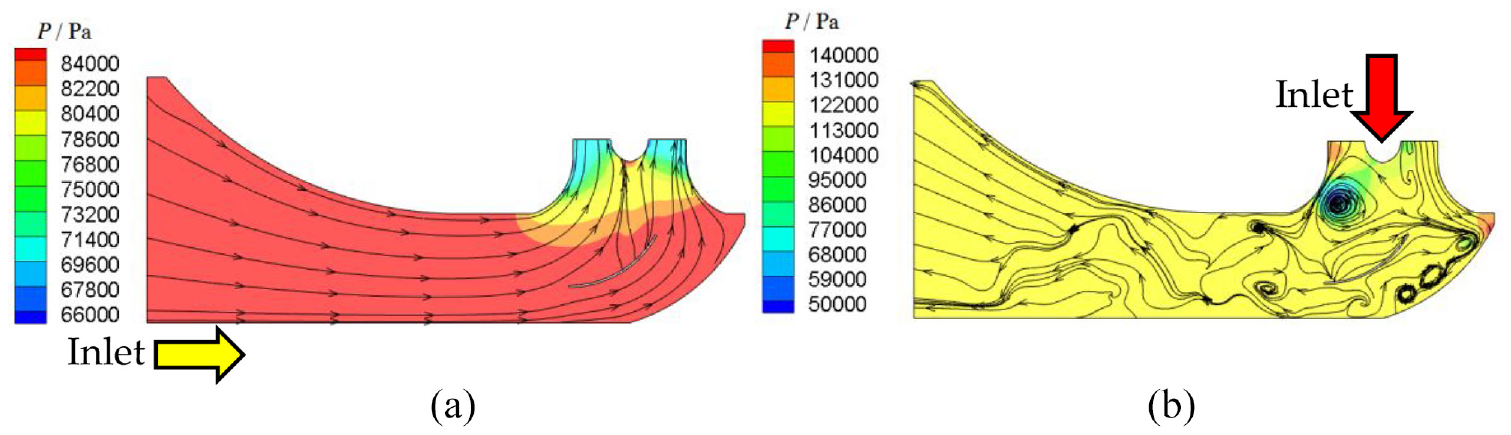
The three-dimensional steady numerical simulation of vertical submersible axial flow pump device is carried out by replacing the wellbore flow conduit with the elbow flow conduit. The flow line and pressure contours of the elbow flow conduit of the vertical submersible axial flow pump device are obtained when the pump device is running in forward operation and reverse operation (Figure 28). When the pump device is running forward, due to the influence of the motor, the bending and torsion of the flow line near the motor in the elbow flow conduit is more serious. In addition, the fluid in the elbow flow conduit has large circulation, so the streamline near the inner wall of the conduit has slight bending and torsion, but there is no vortex in the conduit. When the pump device runs reversely, the flow line inside the conduit is straight and the pressure distribution is uniform, and there is no bad flow pattern inside the channel.

Flow line and pressure contours of the elbow flow conduit: (a) forward operation and (b) reverse operation.
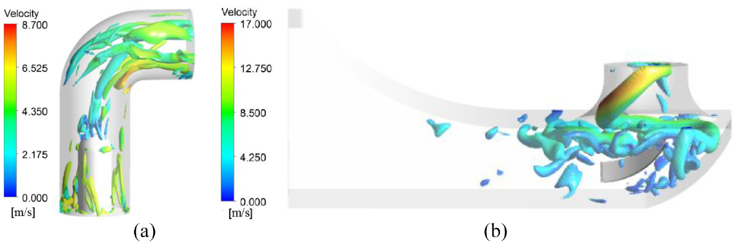
Based on the Q criterion, the vortex state inside the outlet structure of the pump device is identified. The threshold of Q is adjusted to 1000 s−2, and the visible Figure 29 of the vortex shape of the outlet structure under the positive and reverse operation conditions is obtained. It can be seen from Figure 29 that in the forward operation of the pump device, compared with the original wellbore flow conduit (Figure 25), the vortex morphology in the flow channel changes greatly after changing to the elbow flow conduit. At the bottom of the elbow flow conduit, the vortex band caused by the circulation is significantly reduced and the distribution is relatively uniform. At the top of the elbow flow conduit, the vortex flow velocity is more uniform. When the pump device operates in the reverse direction, after the elbow flow conduit is adopted, the vortex band inside the dust-pan-shaped flow conduit is less than that in the original device (Figure 26), the wall attached vortex of the flare tube wall is reduced, the spiral vortex band in the tube is more obvious, and the vortex band accumulated in the area below the flare tube is significantly reduced.

Vortex diagram in outlet structure of pump device: (a) forward operation – elbow flow conduit and (b) reverse operation – dust-pan-shaped flow conduit.
Optimization strategy and analysis ofdust-pan-shaped conduit
When the vertical submersible axial flow pump device runs in the forward direction, the flow line inside the flow conduit is smooth and the hydraulic performance is good. The adverse flow pattern mainly occurs in the wellbore flow conduit. When the pump device runs in the reverse direction, the flow pattern in the dustpan-shaped flow conduit and the wellbore flow conduit is relatively poor. By using the elbow flow channel to replace the wellbore flow channel, the adverse flow pattern of the pump device in the forward direction is basically disappeared. The main reason for the low efficiency of the pump device in reverse operation is the disorder of the internal flow pattern of the dustpan-shaped flow conduit. Since the internal flow pattern of the dust-pan-shaped flow conduit is similar to that of the turbine draft tube, the performance of the reverse operation device of the pump device is improved by setting the guide plate inside the dust-pan-shaped flow conduit.
Influence of guide plate on pump device performance
Referring to the research results of previous scholars,33,34 by setting the guide plate in the draft tube axis to affect the vortex band below the impeller, the impact on the pipe wall can be weakened to achieve the optimization effect. Due to the small height of the dust-pan-shaped flow conduit in this device, the fluid still has great kinetic energy and circulation after flowing out of the impeller and reaching the bottom of the flow conduit, so it is impossible to determine the best installation position of the guide plate. The shaping line of the guide plate is set according to the streamline, so it is not appropriate to change the position of the guide plate on the Z axis (pump axis). This study attempts to increase the width of the guide plate to make it closer to the impeller to strengthen the diversion effect of the guide plate. After numerical simulation verification, it is concluded that due to the excessive circulation of the fluid after flowing out of the impeller, increasing the width of the guide plate will aggravate the impact of the fluid on the guide plate, thereby reducing the efficiency of the device.
The position of the guide plate on the X-axis will affect its diversion effect on the fluid flowing out of the impeller. Assuming that the impeller axis is located at the coordinate origin on the x-axis, it is positive to the right (Figure 30). Seven horizontal values are set at the position of the guide plate in the x-axis direction, which are −0.10D, 0D, 0.13D, 0.27D, 0.40D, 0.53D, and 0.67D respectively. Through modeling and steady numerical simulation, the pump device performance under high-efficiency flow conditions in forward and reverse operation is obtained, as shown in Table 5.

Setting of guide plate.
The calculation formula of device efficiency change in the table is:

Where
Table 5 shows that in the forward operation, the greater the deviation from the initial position of the guide plate, the stronger the flow disturbance effect, the lower the efficiency of the pump device, and the performance of the pump device decreases with the increase of x. In the reverse operation, the device efficiency reaches the maximum when X is 0.27D, and the device head is the highest and the hydraulic loss of the flow conduit is the smallest. The medians of 0.20D and 0.40D in the adjacent interval of 0.27D are taken for three-dimensional modeling and numerical simulation. Compared with the device performance of x = 0.27D, it can be seen from Table 4 that 0.27D is the optimal position of the guide plate scheme. The end of the guide plate near the inlet of the dust-pan-shaped flow conduit is −0.62D on the X axis. The two ends of the Z axis of the guide plate are 1.3D and 0.83D away from the outlet surface of the dust-pan-shaped flow conduit.
Analysis of flow field and vortex state in the conduit after adding guide plate
After installing the guide plate in the dust-pan-shaped flow conduit, carry out the simulation calculation of the constant constant value of the vertical submersible axial flow pump device. The setting method and grid of the deflector are shown in Figure 31. The internal streamline and pressure contours of the dust-pan-shaped flow conduit of the vertical submersible axial flow pump device under the forward and reverse operation of the pump device under standard working conditions are obtained (Figure 32), and the internal flow pattern of the dust-pan-shaped flow conduit without guide plate is compared (Figures 9 and 15). It can be seen that when the pump device is running forward, the setting of guide plate has little impact on the internal flow of the inlet conduit, there is no adverse flow pattern such as vortex in the inlet conduit, and the streamline and pressure distribution are similar to those without guide plate. When the pump device runs in the reverse direction, there are still a large number of vortices in the internal wall area of the dust-pan-shaped flow conduit, and the flow pattern is disordered. However, compared with the internal flow pattern of the conduit without guide plate under the same flow condition, due to the influence of the guide plate, the large-scale vortex at the bottom of the dust-pan-shaped flow conduit becomes a smaller wall attached vortex, and the pressure distribution in the conduit is more uniform, and the flow pattern is improved on the whole.

Dust-pan-shaped flow conduit and grid diagram with guide plate: (a) three-dimensional model and (b) model grid.
Streamline and pressure contours of dust-pan-shaped flow conduit: (a) forward operation and (b) reverse operation.
Based on the Q criterion, the vortex structure of dust-pan-shaped flow conduit and elbow flow conduit with guide plate under high-efficiency working conditions (forward K Q = 0.536, reverse K = 0.368) during forward and reverse operation is identified. As shown in Figure 33, the vortex structure in elbow flow conduit is not significantly different from that without guide plate (Figure 25). After setting guide plate, the vorticity at the bottom of the dust-pan-shaped flow conduit increases, and the vorticity at the top and in the outlet pipe decreases. During the reverse operation of the pump device, compared with the original internal vortex band shape (Figure 26), it can be seen that the setting of the guide plate has a great impact on the internal vortex band of the dust-pan-shaped flow conduit. In Figure 33, there is mainly a thick spiral vortex band under the impeller, which is very similar to the vortex band shape in the draft tube of the hydraulic turbine, In the original installation, it may be because the fluid has a wide range of longitudinal whirling waters at the bottom of the flow conduit, which interferes with the vortex structure in the horn tube, making the wall attached vortex more obvious in the horn tube.
Vortex diagram in outlet structure of pump device: (a) forward operation – elbow flow conduit and (b) reverse operation – dust-pan-shaped flow conduit.
Conclusion
The energy performance of vertical submersible axial flow pump device during forward and reverse operation is predicted, the internal flow characteristics of each overflow structure are analyzed, and the structural optimization and hydraulic analysis of dust-pan-shaped flow conduit and wellbore flow conduit are carried out. The conclusions are as follows:
The hydraulic performance of the pump device is good in the forward operation. The maximum efficiency of the pump device is 72.22%, and the corresponding head is 4.01 m (K Q = 0.430). The flow pattern in the inlet conduit of the pump device is good, and the pressure distribution is uniform. There is a part of vortex in the guide vane inside the back of the guide vane. With the increase of flow rate, the vortex becomes smaller, but there are many vortexes in the elbow flow conduit, which have a great influence on the pump device. In the reverse operation, the performance of the pump device decreased significantly, the maximum efficiency was only 36.03%, and the corresponding head was 3.34 m. The inlet conditions of the wellbore flow conduit were poor, and most of the backflow areas existed in the internal, and the partial flow phenomenon was serious. The convection state of the front guide vane was improved. In the dust-pan-shaped flow conduit, the fluid velocity circulation at the impeller outlet was large, the vortex bands in the horn tube gathered, and there was a large range of backflow areas in the flow conduit.
In the forward operation, the hydraulic loss in the dust-pan-shaped flow conduit is very small. Under the high efficiency condition (K Q = 0.536), the uniformity of axial velocity distribution at the impeller inlet is 83.06%, and the maximum weighted average angle of velocity is 78.31°. However, the wellbore flow conduit affects the performance hydraulic loss of the device, and the maximum hydraulic loss ratio is 43.83%. In the reverse operation, the hydraulic loss in the wellbore flow conduit is large. In the high efficiency condition (K Q = 0.368), the uniformity of axial velocity distribution at the outlet of the wellbore flow conduit is 67.24%, and the minimum weighted average angle is 66.40°. After the flow passes through the guide vane, the uniformity of axial velocity distribution increases to 72.25%, and the weighted average angle of velocity increases to 74.80°. Based on the Q criterion, the vortex pattern inside the outlet conduit is captured. In the forward operation, the vortex band is mainly distributed at the inlet of the wellbore flow conduit and the top of the wellbore and the outlet of the outlet pipe. In the reverse operation, the vortex band inside the dust-pan-shaped flow conduit is mainly concentrated in the horn tube.
The wellbore flow conduit is changed into the elbow flow conduit. When the corner radius is set to 0.83D, the efficiency of the pump device increases by 6.13% in the forward operation and 5.10% in the reverse operation. On the basis of adopting the elbow flow channel, setting the guide plate inside the dustpan-shaped flow channel can reduce the vortex inside the dustpan-shaped flow conduit, which can improve the efficiency of the pump device by 3.52% in reverse operation.
Footnotes
Handling Editor: Chenhui Liang
Declaration of conflicting interests
The author(s) declared no potential conflicts of interest with respect to the research, authorship, and/or publication of this article.
Funding
The author(s) disclosed receipt of the following financial support for the research, authorship, and/or publication of this article: This research was funded by the National Natural Science Foundation of China (Grant No. 51609210, 51779214), Major Projects of the Natural Science Foundation of the Jiangsu Higher Education Institutions of China (Grant No. 20KJA570001), the open research subject of the Key Laboratory of Fluid and Power Machinery, Ministry of Education (Grant No. szjj2016-078), the Technology Project of the Water Resources Department of the Jiangsu Province (Grant No. 2020029), the Scientific Research Program of Jiangsu Hydraulic Research Institute (Grant No. 2020z026), and the Priority Academic Program Development of the Jiangsu Higher Education Institutions (PAPD).